
Related Manuals for Tuxedo FP8K-DS


Summary of Contents for Tuxedo FP8K-DS
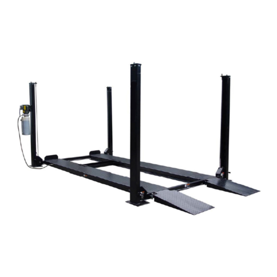
- Page 1 FP8K-DS & FP8K-DS-XLT Four Post Parking Lifts 8000 lb Capacity Installation & Operation Manual REV A-091713...
- Page 3 8,000 ELUXE ERIES TORAGE ERVICE IFTS Smooth operation and good looks make a great first impression but it’s the safety features and durability that makes the “Deluxe Series” the best choice in storage/service lifts. 8 K-DS Deluxe Series Storage / Service lift Features: 8,000 lb.
- Page 4 There is no other express warranty on the Tuxedo lifts and this warranty is exclusive of and in lieu of all other warranties, expressed or implied, including all warranties of merchantability and fitness for a particular purpose.
- Page 5 PREFACE Prior to the operation of your lift make sure that you read the instructions thoroughly. These instructions are found in this manual. Please note that your warranty may be voided if you do not read the manual and understand its content. REV A-091713...
-
Page 6: Important Safety Instructions
IMPORTANT SAFETY INSTRUCTIONS Read these safety instructions entirely! Failure to read these instructions may result in injury to user, other people within the area of the lift, or vehicles. The manufacturer is not responsible for any injury or damage as a result of neglecting to carefully read and follow these instructions. Always lock the lift in place before going under the vehicle. - Page 7 MAINTAIN WITH CARE. Keep lift clean for better and safe performance. Follow instructions in the manual for proper lubrication and maintenance. Keep control handles and/or buttons dry, clean and free from grease and oil. STAY ALERT. Watch what you are doing. Use common sense. Be aware. CHECK FOR DAMAGED PARTS.
- Page 8 SIZE DRAWING Fig. 1 Fig. 2 REV A-091713...
-
Page 9: Specification
SPECIFICATION: 163016/FP8K-DS 163018/FP8K-XLT Specifications Overall Width 2630mm(103.54”) 2780mm(109.45”) Inside Columns 2398mm(94.41”) 2548mm(100.32”) Width of Outside runway 1900mm(74.80”) 2050mm(80.71”) Width of runway 474mm(18.66”) 474mm(18.66”) Overall Length 4460mm(175.59”) 4845mm(190.75”) Min122~max1900mm Min122~Max2090mm Lifting Height (Min4.8”~Max 74.80”) (Min4.8”~Max82.28”) Overall Height 2237mm(88.07”) 2390mm(94.09”) Length of Columns 4000mm(157.48”) -
Page 10: Installation
INSTALLATION Improper installation can cause accelerated wear, resulting in catastrophic failure which may cause property damage and / or bodily injury. Manufacturer will assume no liability for loss or damage of any kind, expressed or implied, resulting from improper installation or use of this product. Read this installation manual in its entirety before attempting to install or operate the lift. - Page 11 STEP 2 UNPACKING Unpack the lift close to the installation site. Review your packing list and assembly drawing to verify that you have all the parts. Layout a chalk line on the floor for the position of columns.. TOOLS recommended "Rotary Hammer Drill Or Similar (If anchoring ) Medium Crescent Wrench 3/4"...
- Page 12 Insert the cross rail into the top of the left and right columns.(Fig. 7) Till it touches the ground. (Fig. 9-10) Note: The side with the hole for the safety latch release bar must be facing out. (Fig. 8) Fig. 7 (cross rail is facing center) Fig.
- Page 13 Insert the safety latch ladder into the column and the end of cross rail. (Fig. 11) and raise the cross rail about one foot to rest on lowest locking position. Fig. 12 F i g . 1 1 Put on the column top cover then bolt it to the column. Be sure that the hole for the cable points towards the center (Fig.
- Page 14 STEP 4 CABLES m the cylinder as far as possible. Pull out the piston rod fro Line the cables according to the drawing (Fig. 16-17). Fig. 14 Fig.15 Fig. 16 Fig.17 STEP 5 Platform installation Put the main platform (the one with cylinder) on the cross rails on the left. (Fig. 18) Put the sub platform on the cross rails on the right.(Fig.
- Page 15 Let the cable go through the cross rail end then bolt to top of column. (Fig. 17-20) Fig. 19 Fig. 20 STEP 6 Safety Latch Linkage Installation Install the safety latch linkage rod and other accessories on the front and rear crossbeam.
-
Page 16: Accessory Mounting
STEP 7 Motor pump and hydraulic hose Mount the motor pump on the main column. Connect the hose from pump to the cylinder.(Fig. 25) Add hydraulic oil to the pump tank. Suggestion: using AW-32 or ISO-32 hydraulic oil, approximately 10L. Hook up the power supply to the motor pump. - Page 17 Now the parking lift is ready for use. REV A-091713...
- Page 18 FP8K-DS/XLT PARTS CODE AND PARTS DRAWING REV A-091713...
- Page 19 FP8K-DS/XLT PARTS CODE AND PARTS DRAWING REV A-091713...
- Page 20 FP8K-DS/XLT PARTS CODE AND PARTS DRAWING REV A-091713...
- Page 21 FP8K-DS/XLT PARTS CODE AND PARTS DRAWING REV A-091713...
- Page 22 FP8K-DS/XLT PARTS CODE AND PARTS DRAWING REV A-091713...
- Page 23 Parts code for FP8K-DS ITEM CODE DESCRIPTION NOTE Main column weldment weldment TT7B-100-01-00 Sub column weldment weldment TT7B-100-02-00 Top plate weldment 1 weldment TT7B-100-04-00 Top plate weldment 2 weldment TT7B-100-03-00 Latch ladder weldment weldment TT7B-100-05-00 Hex nut GB41 Hex nut...
- Page 24 Parts code for FP8K-DS ITEM CODE DESCRIPTION NOTE Spindle weldment TT7B-200-12-00 small roller TT7B-200-13 Plate weldment DPF4-3.2-300-07-00 Baffle plate DPF4-3.2-300-06 Hex Bolt M18X100 GB5780 Spring washer GB93 Hex Nut GB6170 Flat washer GB95 Spindle bushing 4 TT7B-300-01-04 Spindle TT7B-300-01-05 Spindle bushing 3...
- Page 25 Parts code for FP8K-DS ITEM CODE DESCRIPTION NOTE Flat washer GB96 Hex Bolt M6X30 GB5781 Hex Nut GB6170 Angle fitting TT7B-400-03 Throttle Valve TT7B-400-04-00 Hydraulic Hose DPF4-3.2-500-10 Angle fitting DPF4-3.2-500-07 Flat washer GB95 DPF4-3.2-500-06 Hydraulic hose DPF4-3.2-500-11 Tee fitting TPF4-500-05...
-
Page 26: Power Unit Priming Procedure
IMPORTANT POWER UNIT PRIMING PROCEDURE THE PROBLEM: Power unit runs fine but will not pump any fluid. Step 1 – Locate the check valve, the flush plug to the left of the lowering valve. (See drawing below.) Step 2 – Using an Allen wrench and shop towel – with shop towel in place to catch fluid –...
Need help?
Do you have a question about the FP8K-DS and is the answer not in the manual?
Questions and answers
How to install the plastic sheets?