
Related Manuals for Tuxedo FP12K-K


Summary of Contents for Tuxedo FP12K-K
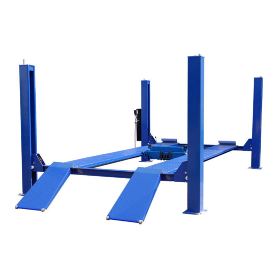
- Page 1 FP12K-K Flat Deck Four-Post Lift 12,000 lb Capacity ASSEMBLY & OPERATION INSTRUCTION MANUAL REV A-083013...
- Page 3 12,000 ABLE Cable driven four post lift provides 12,000 lb. lifting capacity. No power beam; Cylinder stowed under single piece diamond plate track. Simple, lever release system and redundant safety locks. FP 12 K-K 12,000 lb. capacity Four post cable lift Features: FP 12 K-K PECIFICATIONS...
-
Page 4: Limited One-Year Warranty
There is no other express warranty on the Tuxedo lifts and this warranty is exclusive of and in lieu of all other warranties, expressed or implied, including all warranties of merchantability and fitness for a particular purpose. -
Page 5: Important Notes
TABLE OF CONTENTS Important Note--------------------------------------------------------------------------------Page 3 Definition---------------------------------------------------------------------------------------Page 4 Preparation and General Information---------------------------------------------------Page 5 Important Concrete and Anchoring Information--------------------------------------Page 6 Installation and Basic Operation Instruction------------------------------------------Page 7 Safety Procedures--------------------------------------------------------------------------Page 11 Maintenance Schedule--------------------------------------------------------------------Page 12 Troubleshooting-----------------------------------------------------------------------------Page 14 Owners Responsibilities------------------------------------------------------------------Page 15 Packing list ----------------------------------------------------------------------------------Page 16 Installation specification (Fig 2)---------------------------------------------------------Page 17 Prepare area (Fig 3)-----------------------------------------------------------------------Page 18 Cable wiring (Fig 20)----------------------------------------------------------------------Page 19... - Page 6 REV A-083013...
-
Page 7: General Information
PREPARATION The installation of this lift is relatively simple and can be accomplished by 2 men in a few hours. The following tools and equipment are needed: AW 32,46 Non-Detergent Non-Foaming Anti-Wear Hydraulic Oil SAE-10 (12 quarts) Chalk line and 12’ Tape Measure, Transit and a 4’ Level Rotary Hammer Drill with 3/4”... - Page 8 REV A-083013...
- Page 9 REV A-083013...
- Page 10 Double check all dimensions and make sure that the layout is perfectly square. Before continuing with the installation it is helpful to stand the posts up at their respective locations and get a visual of the shop, aisles and other clearances. Also, this is a good time to drive a vehicle into position and check for adequate clearance.
- Page 11 REV A-083013...
- Page 12 Fig. 13 Fig.14 Fig.15 2. Using bolts provided, bolt the right-rear end of the off-side runway on the rear cross bar. The other end is free. 3. Before locating the power-side runway on the cross bars, pull out the cables underneath and put them over the pulleys.
-
Page 13: Operation
to size the wire for a 25 amp circuit. STEP 7: (Routing the CABLES) Check again that all the cables are on the pulleys both of the columns and underneath the power-side runway. Make sure that the current of the power supply is enough for the motor. Press the start button on the motor to raise the runways a little. - Page 14 REV A-083013...
- Page 15 REV A-083013...
- Page 16 REV A-083013...
- Page 17 REV A-083013...
-
Page 18: Packing List
Packing List Description Note Power-side runway with cylinder ,hose and cables Off-side runway Front cross bar With lock release handle Rear cross bar Power-side column With mounting holes for pump Off-side column Column cover Front stop Approaching ramp Long lock linkage rod Beam cover Accessory box Anchors and shims... - Page 19 ITEM MODEL 165972 Overall Width 3120mm Inside Columns 2660mm Inside Soleplate of columns 2560mm Between Runways 928mm Length of Ramp 910mm Length of Runway 4860mm Width of Outside runway 1980mm Width of runway 482mm Size of Soleplate 280*280mm Overall Length 4960mm Lifting Height 1760mm...
- Page 20 INSTALLATION INSTRUCTION Fig 3 (These data are suggestion not min. requirement) REV A-083013...
- Page 21 INSTALLATION INSTRUCTION Fig 20 REV A-083013...
- Page 22 INSTALLATION INSTRUCTION Fig 21 REV A-083013...
-
Page 23: Spare Parts List
FP12K-K Spare Parts List ITEM DESCRIPTION Main column parts 1 Column parts 2 Column parts 3 Cross beam parts 1 Hiding board Z Cross bolt Flat washer C Cross beam parts 2 Runaway 1 Runaway 2 Hexangular bolt C Hexangular nut C... - Page 24 FP12K-K Spare Parts List DESCRIPTION ITEM Hexangular nut Flat washer C Safty card Beam wheel 3 Beam wheel 2 Steel cable Hexangular nut 19.1 Flat washer C 19.2 Snap ring Cable stable Cable block 2 Cable block 1 22.1 Inner hexangular screw 22.2...
- Page 25 FP12K-K Spare Parts List ITEM DESCRIPTION Runaway 1 jointing parts Big washer A & C Z Cross bolt Pose pump board Safty transmission pole clasp Hexangular nut 6.11 Hexangular bolt C 6.12 Flat washer C 6.13 Orientation bolt 6.14 Profiled bar connection 6.17...
- Page 26 FP12K-K Spare Parts List ITEM DESCRIPTION ITEM DESCRIPTION Safty idler wheel Safty screw pole1 Safety bolck1 Safty screw pole 2 Spindle 1 Safty handle spindle 35.1 Spring washer A Connection Handle safty 1 Safty transmission pole Spindle pull handle Beam 1 jointing...
-
Page 28: Power Unit Priming Procedure
IMPORTANT POWER UNIT PRIMING PROCEDURE THE PROBLEM: Power unit runs fine but will not pump any fluid. Step 1 – Locate the check valve, the flush plug to the left of the lowering valve. (See drawing below.) Step 2 – Using an Allen wrench and shop towel – with shop towel in place to catch fluid –...
Need help?
Do you have a question about the FP12K-K and is the answer not in the manual?
Questions and answers