Tuxedo TP12KFX Manual

Tuxedo TP12KFX Manual

12kx/15kx two post lift, symmetric floor plate/clear floor

Advertisement

Quick Links

T P 1 2 K F X , T P 1 5 K C X
1 2 K X T w o P o s t L i f t , S y mme t r i c F l o o r P l a t e
1 5 K X T w o P o s t L i f t , S y mme t r i c C l e a r F l o o r
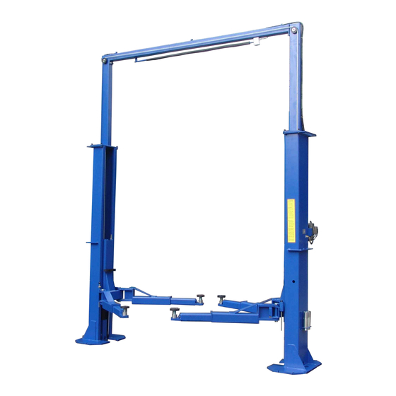
I n t r o d u c i n g t h e N e w T P 1 2 K & T P 1 5 K ' X ' H D S e r i e s T w o P o s t L i f t s ! ! T h e n e w T P 1 2 K F X &
T P 1 5 K C X T w o P o s t F l o o r P l a t e & C l e a r F l o o r L i f t s h a v e b e e n r e d e s i g n e d a n d n o w c o me
s t a n d a r d w i t h L o w p r o f i l e D r o p - I n A d j u s t a b l e S w i v e l P a d s w i t h H e i g h t A d a p t e r s , I n t e r n a l
H o s e R o u t i n g , P a d d e d O v e r h e a d S h u t - O f f B a r w i t h K i l l S w i t c h , r e d u c e d o v e r a l l Wi d t h , &
R u b b e r D o o r G u a r d s , ma k i n g t h e s e mo d e l s s o me o f t h e b e s t h e a v y d u t y T w o P o s t L i f t
v a l u e s i n t h e i n d u s t r y !
S t a n d a r d F e a t u r e s :
• H i g h Q u a l i t y L i f t s
• C h a i n D r i v e
• D u a l P o i n t L o c k R e l e a s e
• P o w d e r c o a t f i n i s h
N e w ! ! T P 1 2 K F X & T P 1 5 K C X ' X ' F e a t u r e s :
• L o w P r o f i l e ' D r o p - i n ' S w i v e l P a d s w / 2 " a d j u s t a b l e h e i g h t
• L o w P r o f i l e ' D r o p - i n
• P a d d e d ' S h u t O f f ' B a r w / K i l l S w i t c h
• 4 e a S t a c k a b l e 3 " & 5 " ' d r o p - i n ' H e i g h t A d a p t e r s
• R e d u c e d o v e r a l l Wi d t h w / f r o n t - s i d e mo u n t e d P o w e r U n i t
• I n t e r n a l H o s e R o u t i n g w / i n t e g r a t e d H o s e G u a r d s
• R u b b e r D o o r G u a r d s
3 / 0 7 / 1 7 T P 1 2 - T P 1 5 R e v 1

Advertisement

Table of Contents
loading
Need help?

Need help?

Do you have a question about the TP12KFX and is the answer not in the manual?

Questions and answers

Summary of Contents for Tuxedo TP12KFX

  • Page 1 T P 1 2 K F X , T P 1 5 K C X 1 2 K X T w o P o s t L i f t , S y mme t r i c F l o o r P l a t e 1 5 K X T w o P o s t L i f t , S y mme t r i c C l e a r F l o o r I n t r o d u c i n g t h e N e w T P 1 2 K &...
  • Page 2 T P 1 2 K F X , T P 1 5 K C X 1 2 K X T w o P o s t L i f t , S y mme t r i c F l o o r P l a t e 1 5 K X T w o P o s t L i f t , S y mme t r i c C l e a r F l o o r N e w ! ! T P 1 2 &...
  • Page 3 TP15KC-KX Two-Post Clear Floor Lift (Symmetric) 15,000 lbs. Capacity (3,750 lbs. Max per Arm) ASSEMBLY & OPERATION INSTRUCTION MANUAL Feb. 2017...
  • Page 4: Important Notes

    IMPORTANT NOTES READ THE INSTALLATION AND OPERATION MANUAL IN ITS ENTIRETY BEFORE ATTEMPTING TO INSTALL THE LIFT. • Do not install this lift on any surface other than concrete, confirming to minimum specifications. • Do not install this lift over expansion joints or cracks. Check with building architect. •...
  • Page 5: General Information

    PREPARATION The installation of this lift is relatively simple and can be accomplished by 2 men in a few hours. The following tools and equipment are needed: • 12 quarts of Non-Detergent / Non-Foaming Hydraulic Oil - SAE-10, AW 32 or equivalent •...
  • Page 6 TP15KCX Feb 2017...
  • Page 7: Installation Instructions

    INSTALLATION INSTRUCTIONS STEP 1: (Selecting Site) Before installing your new lift, check the following: LIFT LOCATION: Always use architects plans when available. Check layout dimension against floor plan requirements making sure that adequate space is available (Fig. 2 & Fig. 3). Fig.
  • Page 8 Fig. 3 (Column / Floor Layout) OVERHEAD OBSTRUCTIONS: The area where the lift located should be free of overhead obstructions such as heaters, building supports, electrical lines etc. (Figs 2 & 3.) DEFECTIVE CONCRETE: Visually inspect the site where the lifts will be installed and check for cracked or defective concrete.
  • Page 9 STEP 2: (Unloading & Unpacking) After unloading the lift, place it near the intended installation location. Remove the shipping bands and packing materials from the unit. Remove the packing brackets and bolts holding the two columns together. (Do not discard bolts, they may be used in the assembling of the lift ) Take out the overhead beam, uprights, lifting arms, swivel pads, height extensions, hardware box, hoses, covers, etc., from the column.
  • Page 10 Using the base plate on the MAIN column as a guide, drill each anchor hole in the concrete approximately ” deep using a rotary hammer drill and ” concrete drill-bit. To assure full holding power, do not ream the hole or allow the drill to wobble. (See Anchoring Details on Page 4) After drilling, remove dust thoroughly from each hole using compressed air and/or wire brush.
  • Page 11 Using a lifting device, raise the Overhead Beam assembly and connect to uprights at each end, using the bolts, nuts and washers, as shown in (Fig. 9). Use a tape measure to measure the diagonal distance between the opposite corners of the base plates on the columns. Equal values will ensure the lifting arms will be in square.
  • Page 12 STEP 7: (Installing / Routing EQUALIZER CABLES) Cont. Cable Routing Diagram Fig. 14 Repeat above for the second cable. Adjust each equalizer cable to approximately 1/2” side-to-side play. Ensure that each cable has equal tension. Check the carriage height to ensure both carriages are sitting on the same latch. TP15KCX Feb 2017...
  • Page 13 STEP 8: (Installing / Routing HYDRAULIC HOSES, HYDRULIC FITTINGS & HOSE COVERS) 1. Install & connect hydraulic hoses, fittings and hose covers, as shown below in (Figs. 15-17) along with the Exploded View #2 diagram on page 22. NOTE: It is necessary to have hoses routed through Hose Covers (Fig. 17), along with ensuring the hydraulic T-Fitting’s threads are fully tightened against the outside of Main column, as shown in (Figs.
  • Page 14 STEP 9: (Installing Swing Arms & Arm Restraints) Cont. Install arm restraint mechanisms to each swing arm, as shown below in (Fig. 18). Check for proper engagement for the arm restraints as the gear rack should fully engage the gear on the arm.
  • Page 15 STEP 10: (Electrical Connection to POWER UNIT & OVERHEAD LIMIT SWITCH) 1. Have a certified electrician make the electrical connection to the power unit. Use separate circuit for each power unit, as shown below in (Fig. 19). Fig. 19 IMPORTANT! The wiring must comply with local code. Protect each circuit with time delay fuse or circuit breaker.
  • Page 16 STEP 11: (Checking Operation) See next page for detailed Operation Instructions: Do not place any vehicle on the lift at this time. Cycle the lift up and down several times to ensure carriage latches click together and all air is removed from the hydraulic system.
  • Page 17 IMPORTANT! Read Safety & Operating Information on following pages before using lift. OPERATION INSTRUCTIONS RAISE LIFT 1. Read operating and safety manuals before using lift. 2. Always lift a vehicle according to the manufacturers recommended lifting points 3. Position vehicle between columns, as equally as possible. 4.
  • Page 18: Safety Procedures

    SAFETY PROCEDURES • Never allow unauthorized persons to operate lift. Thoroughly train new employees in the operation and care of lift. • Caution: the power unit operates at high pressure. • Remove passengers before raising vehicle. • Prohibit unauthorized persons from being in shop area while lift is in use. •...
  • Page 19 WARNING OSHA AND ANSI REQUIRE USERS TO INSPECT LIFTING EQUIPMENT AT THE START OF EVERY SHIFT. THESE AND OTHER PERIODIC INSPECTIONS ARE THE RESPONSIBILITY OF THE USER. DAILY PRE-OPERATION CHECK (8 HOURS) The user should perform daily check. Daily check of the safety latch system is very important the discovery of device failure before needed could save you from expensive property damage, lost production time, serious personal injury and even death.
  • Page 20 Only a trained maintenance experts should perform the following items. • Replace hydraulic hoses • Replace chains and rollers. • Replace cables and sheaves. • Replace or rebuild air and hydraulic cylinders as required. • Replace or rebuild pumps / motors as required. •...
  • Page 21: Troubleshooting

    TROUBLE SHOOTING 1. Motor does not run: A. Breaker or fuse blown B. Faulty wiring connections. Call electrician. C. Defective up button. Call electrician for checking. D. Defective Capacitor. Call electrician for checking. 2. Motor runs but will not raise: A.
  • Page 22: Power Unit Priming

    POWER UNIT PRIMING TP15KCX Feb 2017...
  • Page 23: Exploded View

    EXPLODED VIEW #1 TP15KCX Feb 2017...
  • Page 24 EXPLODED VIEW #2 TP15KCX Feb 2017...
  • Page 25: Parts List

    PARTS LIST ITEM Tux P/N M-Ref P/N DESCRIPTION NOTES TP15KC-KX-001 TT-6861KY-101-01-00A Mainside Column TP15KC-KX-002 TT-6861KY-101-01-00B Offside Column TP15KC-KX-003 TT-6861KY-103-01-00 Upright TP15KC-KX-004 TT-6961KY-300-03-00 Low Adaptor 3” (12/15KX) TP15KC-KX-005 TT-6961KY-300-02-00 High Adaptor 5” (12/15KX) TP15KC-KX-006 TT-6961KY-103-01 Adaptor Bracket (12/15KX) Q235 TP15KC-KX-007 GB95-1985 D8 Flat Washer D8 TP15KC-KX-008 GB818-85 M8X10...
  • Page 26 TP15KC-KX-041 TT-6934-046405772 Rubber Pad, Swivel Pad Rubber TP15KC-KX-042 TT-6961KY-048417190L Swivel Pad Weldment TP15KC-KX-043 TT-6961KY-048417160 Swivel Pad, Screw Collar TP15KC-KX-044 GB895.2-1986 D35 Circlip D35 TP15KC-KX-045 TT-6961KY-200-01-00 Carriage (12/15KX) TP15KC-KX-046 TPO15-200-04 Sliding Rub Block TP15KC-KX-047 DL38G-C116A Rubber Door Guard (12/15KX) Rubber TP15KC-KX-048 GB70.1-2000 M8X35 Screw M8x35 TP15KC-KX-049...
  • Page 27 TP15KC-KX-077 TT-6961KY-500-01 MS, Short, Hyd. Hose - 13.4” L=340mm TP15KC-KX-078 TT-6961KY-500-02 MS, Low Hyd. Hose - 63.2” L=1605mm TP15KC-KX-079 TT-6934-500-04KY Pump Hyd. Fitting TP15KC-KX-080 O-Ring TP15KC-KX-081 PU-220V-L-H-X 220V Power Unit DURO TP15KC-KX-082 GB5781-86 M8X25 Bolt M8x25 TP15KC-KX-083 GB95-1985 D8 Flat Washer D8 TP15KC-KX-084 GB93-1987 D8 Lock Washer D8...
  • Page 28 TP15KCX Feb 2017...

This manual is also suitable for:

Tp15kcx

Table of Contents