Table of Contents
Advertisement
Quick Links
Advertisement
Table of Contents
Troubleshooting

Related Manuals for Furuno FI70DSW


Summary of Contents for Furuno FI70DSW
- Page 1 OPERATOR'S MANUAL COLOR INSTRUMENT FI-70 Model www.furuno.com...
- Page 2 The paper used in this manual is elemental chlorine free. ・FURUNO Authorized Distributor/Dealer 9-52 Ashihara-cho, Nishinomiya, 662-8580, JAPAN A : JAN 2015 Printed in Japan All rights reserved. G2 : NOV . 16, 2021 Pub. No. OME-72810-G2 (YOTA ) FI-70...
- Page 3 How to discard a used battery Some FURUNO products have a battery(ies). To see if your product has a battery, see the chapter on Maintenance. If a battery is used, tape the + and - terminals of the battery before disposal to pre- vent fire, heat generation caused by short circuit.
- Page 4 SAFETY INSTRUCTIONS The operator and installer must read the applicable safety instructions before attempting to operate or install the equipment. Indicates a potentially hazardous situation which, if not avoided, WARNING could result in death or serious injury. Indicates a potentially hazardous situation which, if not avoided, CAUTION can result in minor or moderate injury.
-
Page 5: Table Of Contents
TABLE OF CONTENTS FOREWORD ........................v SYSTEM CONFIGURATION ..................vi EQUIPMENT LISTS....................... vii OPERATION AND CONTROLS OVERVIEW............1-1 1.1 Controls ........................1-1 1.2 How to Turn the Power On/Off ...................1-1 1.3 How to Adjust the Screen Brilliance ................1-2 1.4 Menu Overview......................1-2 1.5 How to Turn Key Beeps On/Off ..................1-3 1.6 How to Adjust the Panel Dimmer (Control Key Panel Backlights)......1-4 1.7 Screen Categories and Page Setup ................1-4 1.7.1... - Page 6 TABLE OF CONTENTS 3.9 Anchor Alarm ......................3-8 3.10 CPA/TCPA Alarms ..................... 3-9 SYSTEM MENU .....................4-1 4.1 CAN bus (NMEA2000) Network Shared Settings ............4-1 4.1.1 How to adjust the sharing level ..............4-2 4.2 How to Share Language and Brilliance Settings Between FI-70s......4-3 4.3 How to Set the Display Format ..................
-
Page 7: Foreword
FOREWORD A Word to the Owner of the FI-70 Congratulations on your choice of the FURUNO FI-70 Color Instrument. We are confident you will see why the FURUNO name has become synonymous with quality and reliability. Since 1948, FURUNO Electric Company has enjoyed an enviable reputation for quality marine electronics equipment. -
Page 8: System Configuration
SYSTEM CONFIGURATION Analog sensors Wind Transducer FI-5001/L Speed/Temp. Sensor Tank gauge ST-02MSB/ST-02PSB Color Instrument FI-70 (Maximum 11 units) Analog NMEA Data Converter IF-NMEAFI 12 VDC CAN bus/NMEA2000 sensors 15 VDC T-connector Junction Box Junction Box (option) FI-5002 FI-5002 CAN bus/NMEA2000 Backbone Terminal resistor* Terminal resistor* (option) -
Page 9: Equipment Lists
EQUIPMENT LISTS Standard Supply Name Type Code No. Remarks Color Instrument FI-70 Includes soft cover. Installation Materials CP26-02000 000-027-046 Contains CP26-02001 installation materials. Optional Supply Name Type Code No. Remarks Analog NMEA IF-NMEAFI Data Converter Wind FI-5001 Transducer FI-5001L Junction Box FI-5002 Front Mount Kit OP26-29 001-353-090... - Page 10 EQUIPMENT LISTS This page is intentionally left blank. viii...
-
Page 11: Operation And Controls Overview
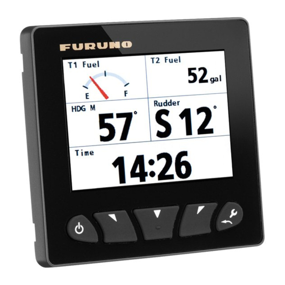
OPERATION AND CONTROLS OVERVIEW Controls Display area º indications Power/Brill Menu/Back Left Software Right Software Function key The information shown in the display area varies depending on the category chosen to be displayed. Functions Power/Brill key Turn power on/off; open the [Brilliance] setting window. Software keys Go back /forward one page;... -
Page 12: How To Adjust The Screen Brilliance
1. OPERATION AND CONTROLS OVERVIEW How to Adjust the Screen Brilliance Press the Power/Brill key to show the [Brilliance] setting Brilliance window. The software keys decrease or increase bril- liance. Pressing the Power/Brill key repeatedly cycles through the brilliance levels. Press the function key to switch between Day and Night modes. -
Page 13: How To Turn Key Beeps On/Off
1. OPERATION AND CONTROLS OVERVIEW 4. Press the software keys to select the item you wish to adjust, then press the function key. The setting options pop-up window is displayed. Power Boat Sailboat Engine Motor Numerical Setting pop-up options pop-up 5. -
Page 14: How To Adjust The Panel Dimmer (Control Key Panel Backlights)
1. OPERATION AND CONTROLS OVERVIEW How to Adjust the Panel Dimmer (Control Key Panel Backlights) 1. Press the Menu/Back key to open the main menu. 2. Press the software keys to scroll down the System menu and select [System], then press the Key Beep: function key. -
Page 15: How To Change The Displayed Page
1. OPERATION AND CONTROLS OVERVIEW 1.7.1 How to change the displayed page The FI-70 can display up to seven different pages of information. Use the software keys to change pages backwards and forwards between the pages. The number of the current page is displayed as a large numeral in the center of the screen for three seconds after the page is displayed. -
Page 16: How To Set Up Pages
1. OPERATION AND CONTROLS OVERVIEW 1.7.2 How to set up pages The FI-70 is capable of displaying seven pages of category information. The procedure below outlines how to set up a page. 1. Press the Menu/Back key to display the main menu. 2. - Page 17 1. OPERATION AND CONTROLS OVERVIEW 3) Press the software keys to select the appropriate data to display, then press the function key. Depth Depth is shown on graph W Temp. Water temperature is shown on graph A Temp. Atmospheric temperature is shown on graph A Press.
- Page 18 1. OPERATION AND CONTROLS OVERVIEW This page is intentionally left blank.
-
Page 19: Display Categories And Category Specific Menus
DISPLAY CATEGORIES AND CATEGORY SPECIFIC MENUS This chapter explains the various menu operations and on-screen indications for each display category. Depending on the data currently selected to be displayed, the analog and digital data displayed on-screen may differ. Data input from external sources may exceed the displayable value on the FI-70. In such cases, the FI-70 displays the maximum value with an asterisk indicated. -
Page 20: Speed Category
2. DISPLAY CATEGORIES AND CATEGORY SPECIFIC MENUS Speed Category The speed category is available in of two formats: • Speed (STW/SOG): displays the ship speed on a tachometer-style meter. • 3-Axis: displays the ship speed in digital format with transverse speed for fore and aft. -
Page 21: Engine Category
2. DISPLAY CATEGORIES AND CATEGORY SPECIFIC MENUS Engine Category Note: Data shown in the engine category is input from engine sensors. Always check any malfunction at the engine, do not rely solely on the FI-70 indication Engine RPM x1000 Currently selected gear is highlighted. F: Forward, N: Neutral, R: Reverse Status indications Eng. -
Page 22: Graph Category
2. DISPLAY CATEGORIES AND CATEGORY SPECIFIC MENUS Graph Category 30min 30min 30min 30min 4300 4300 4300 4300 Depth Depth 4256 4256 4400 4400 30min 30min 4400 4400 1000 1000 Depth Depth A Press. A Press. 4303 4303 1003 1003 4500 4500 The graph category displays preselected sensor data in graph format. -
Page 23: Highway Category
2. DISPLAY CATEGORIES AND CATEGORY SPECIFIC MENUS Highway Category Destination/Waypoint name WAYPOINT Destination/Waypoint mark Own ship mark 0.05 Press the function key to change data displayed. The highway display provides a graphic presentation of your boat’s track along the intended course, toward a waypoint. Press the function key to cycle through the following data on the Highway display: Displayable data Description... -
Page 24: Timer Category
2. DISPLAY CATEGORIES AND CATEGORY SPECIFIC MENUS Timer Category Time Time 15:00 15:00 00:00 00:00 Trip Countdown Timer1 Countdown Timer2 Time 00:00 Countdown Timer 00:00 Lap time Trip meter Trip Countup Timer Countup Timer The Timer category has three available timers to select from, as indicated in the figure above. -
Page 25: How To Adjust The Timers
2. DISPLAY CATEGORIES AND CATEGORY SPECIFIC MENUS 2.7.2 How to adjust the timers 1. With the timer screen displayed, press the function key to show the [Func] key indications. The left software key indication is blank for the [Countup] timer. Setup Start Reset... -
Page 26: Wind Category
2. DISPLAY CATEGORIES AND CATEGORY SPECIFIC MENUS Wind Category º º º AWA/TWA CH AWA/CH TWA Ground Wind Wind Angle Ground Wind* Data display Display mode T: True A: Apparent *: Heading, AWA/AWS and STW data are required to display Ground Wind. This category displays various wind data. -
Page 27: Ais Category
2. DISPLAY CATEGORIES AND CATEGORY SPECIFIC MENUS AIS Category H-UP N-UP Heading Up North Up The AIS category displays basic AIS data such as bearing, range, lost and dangerous targets. The maximum number of targets which may be displayed is 25, in order from closest to farthest from own ship. -
Page 28: How To Display Ais Target Details
Press the right software key to cycle through the targets, in order, from farthest to closest. 3. Press the function key to select a target and display its details. AIS details (Page 1) AIS details (Page 2) Target vessel’s name Furuno Furuno Range to Target’s MMSI ID MMSI: 0123456789 RNG: target Target’s Call Sign... -
Page 29: Satellite Position (Skyplot) Category
2. DISPLAY CATEGORIES AND CATEGORY SPECIFIC MENUS 2.10 Satellite Position (Skyplot) Category Position fixing mode and accuracy level Dilution of Position Blocked area Satellite location and elevation Own ship Signal to Noise Ratio Antenna height 21.9 m ANT1 Selected antenna Elevation mask The satellite position category shows the location of available satellites, along with rel- evant tracking and satellite position information. -
Page 30: Custom Box Category
2. DISPLAY CATEGORIES AND CATEGORY SPECIFIC MENUS 2.11 Custom Box Category Depth W Temp. 3855 3855 º COG M º 42.5 42.5 POSN º º 37.145’N 37.145’N º º 29.108’W 29.108’W The Custom Box category allows you to customize the display, dividing the display area with up to 6 boxes. -
Page 31: How To Customize The Data Boxes
2. DISPLAY CATEGORIES AND CATEGORY SPECIFIC MENUS 2.11.1 How to customize the data boxes With the Custom Box screen displayed, the key indications show "Edit" as the function key function. 1. Press the function key to begin customizing the boxes. The selected box is highlighted in blue. -
Page 32: How To Resize Data Boxes
2. DISPLAY CATEGORIES AND CATEGORY SPECIFIC MENUS 2.11.2 How to resize data boxes 1. With the Custom Box category displayed, press the function key. 2. Press the software keys to highlight the data box to be resized, then press the function key. -
Page 33: Data Which May Be Displayed In Custom Boxes
2. DISPLAY CATEGORIES AND CATEGORY SPECIFIC MENUS 2.11.3 Data which may be displayed in custom boxes The table below shows the data which may be displayed in custom boxes and the box sizes available when resizing the boxes. Box sizes available Data type Displayed data (Height ×... -
Page 34: 3-Axis Speed
2. DISPLAY CATEGORIES AND CATEGORY SPECIFIC MENUS 2.11.4 3-Axis Speed When connected to the same network as a sensor that outputs 3-Axis Speed, the FI- 70 can display three speed locations; fore (bow), center (CCRP), and aft (stern). Note: 3-Axis Speed requires ship dimensions and reference points on your vessel. Make sure that the connected sensor is configured correctly. -
Page 35: Alarms
ALARMS This section explains how to set and use the [Alarms] menu. Most alarms may be ac- cessed from the respective category menu, however, settings made in the [Alarms] menu are applied to each category. To access and set alarm from the [Alarms] menu, do the following: 1. -
Page 36: Stw Alarm And Sog Alarm
3. ALARMS STW Alarm and SOG Alarm The STW and SOG alarms set a high speed or low speed alarm threshold. When the vessel speed goes over the high speed threshold, or below the low speed threshold, the alarm is activated. 1. -
Page 37: Wind Speed/Direction Alarms
3. ALARMS Wind Speed/Direction Alarms 3.3.1 TWS alarm The TWS alarm sets a true wind speed alarm threshold. When the TWS goes over the set threshold, the alarm is activated. 1. Access the [Alarms] menu, using the procedure outlined on page 3-1. 2. -
Page 38: Trip Alarm
3. ALARMS Trip Alarm The trip alarm is activated when the total distance traveled reaches the set threshold. The total distance traveled is calculated from the moment the FI-70 is powered for the first time. This distance is stored in the trip log. 3.4.1 How to set the trip alarm 1. -
Page 39: Depth Alarm
3. ALARMS Depth Alarm The depth alarm activates when the depth is either above or below the set threshold. 1. Access the [Alarms] menu, using the procedure outlined on page 3-1. 2. Press the software keys to select [Depth Alarm], then press the function key. 3. -
Page 40: Water Temperature Alarm
3. ALARMS Water Temperature Alarm The water temperature alarm warns you when the temperature goes over or under the set threshold. The average temperature may also be used as a threshold and is calculated over one minute intervals. 1. Access the [Alarms] menu, using the procedure outlined on page 3-1. 2. -
Page 41: Engine Alarms
3. ALARMS Engine Alarms The engine alarm is activated when the FI-70 receives information containing errors or alarms from the engine. The indicators shown in the table below are normally displayed in gray when the engine category is selected. When an alarm is active, the corresponding indicator flashes and the color changes to an orange-red. -
Page 42: Anchor Alarm
3. ALARMS Anchor Alarm The anchor alarm activates when the vessel exceeds the selected distance from the point at which the alarm was set, or the depth is higher/lower than the depth threshold setting. This alarm is useful when at a standstill or not at the helm. Where Anchor Alarm Where Anchor Alarm Gray... -
Page 43: Cpa/Tcpa Alarms
3. ALARMS 3.10 CPA/TCPA Alarms The CPA (Closest Point of Approach) and TCPA (Time to Closest Point of Approach) alarms activate when the distance between your vessel and an AIS target is smaller than the threshold set. This alarm is used as an aid to avoid collision. Note: The CPA and TCPA alarms are a navigational aid only. - Page 44 3. ALARMS This page is intentionally left blank. 3-10...
-
Page 45: System Menu
SYSTEM MENU This chapter explains the various items in the [System] menu which have not been explained yet. To open the [System] menu, do the following: 1. Press the Menu/Back key to display the main menu. 2. Press the software keys to select [System], then press the function key. System Key Beep: Panel Dimmer:... -
Page 46: How To Adjust The Sharing Level
4. SYSTEM MENU 4.1.1 How to adjust the sharing level 1. Access the System menu using the procedure outlined on page 4-1. 2. Press the software keys to scroll through the menu and select [Sharing], then press the function key. System Key Beep: Stand Alone... -
Page 47: How To Share Language And Brilliance Settings Between Fi-70S
4. SYSTEM MENU How to Share Language and Brilliance Settings Between FI-70s The [Language] and [Brilliance] settings may shared within a group of FI-70s. If the settings are adjusted for one FI-70 unit in the group, all other FI-70 units are also adjusted, however, TZtouch2 unit settings are not adjusted. -
Page 48: How To Set The Display Format
4. SYSTEM MENU How to Set the Display Format The format in which date, time and other displayed items are shown may be set from the [Display Format] menu. The [Display Format] is accessed from the [System] menu. Display Format HDG/COG Ref: Magnetic Mag. -
Page 49: How To Adjust The Engine Settings
4. SYSTEM MENU How to Adjust the Engine Settings The number of engines aboard the vessel and which engine number is used as a display data source are set from the [Engine Setup] menu. Note: The following settings must be completed in order to display correct engine data on the FI-70. - Page 50 4. SYSTEM MENU Where [Number of Engine] is set to [3] [Engine PORT]: Select the engine to use as the port-side data source. [Engine STBD]: Select the engine to use as the starboard-side data source. [Engine Center]: Select the engine to use as the center data source. Engine selected at [Engine Center] Eng.
-
Page 51: How To Set The Displayed Scale Range
4. SYSTEM MENU How to Set the Displayed Scale Range The displayed range for speed, engine and custom box meters may be adjusted by following the procedure below. Data input from external sources may exceed the displayable value on the FI-70. In such cases, the FI-70 displays the maximum value with an asterisk indicated. -
Page 52: How To Set Up The If-Nmeafi (Option)
4. SYSTEM MENU How to Set Up the IF-NMEAFI (Option) The optional IF-NMEAFI is required when inputting data from analog NMEA equipment to the FI-70. Set the IF-NMEAFI up as follows. 4.6.1 IF-NMEAFI menu settings 1. Access the [System] menu using the procedure outlined on page 4-1. 2. -
Page 53: How To Test The If-Nmeafi
4. SYSTEM MENU 4.6.2 How to test the IF-NMEAFI 1. Access the [System] menu using the procedure outlined on page 4-1. 2. Press the software keys to select [IF-NMEAFI], then press the function key. 3. [Select IF] is already selected, press the function key. 4. -
Page 54: How To Setup The Sc-30
4. SYSTEM MENU How to Setup the SC-30 ™ You can setup a SATELLITE COMPASS SC-30 from the [SC-30 Setup] menu. The SC-30 must be connected to the same network as this FI-70. 1. Access the [System] menu using the procedure outlined on page 4-1. 2. - Page 55 4. SYSTEM MENU Menu item Description [Ship Enter the ship’s information and mounting position of the SATEL- Size/ANT ™ LITE COMPASS Position] Enter the appropriate value according to the ship’s size, to improve the accuracy of the 3-axis speed. The reference position for mount- ing position and calculating position of the 3-axis speed are shown in the following figure: Reference...
-
Page 56: How To Interpret The I/O Setup Menu
4. SYSTEM MENU Menu item Description [System Information] Show the system information (ex. software program ™ number) of the SATELLITE COMPASS Note: For SCX-20, the OS program number is not shown. [Factory Default] ™ Restore the SATELLITE COMPASS to the factory default. -
Page 57: How To Set The Data Source(S)
4. SYSTEM MENU [ICOM AIS Data] Select [Yes] to use the AIS data output from a AIS transponder manufactured by ICOM. 4.10 How to Set the Data Source(s) The FI-70 automatically detects and connects to data sources within the network. These settings can be changed as required by doing the following: 1. -
Page 58: How To Setup The Tanks
4. SYSTEM MENU 4.11 How to Setup the Tanks The FI-70 can show information for up to six tanks. The tanks must be connected to the same network as the FI-70. If your tank has a single sensor installed, tank data is automatically supplied to the FI- 70 and the following procedure is not required. -
Page 59: How To Adjust (Calibrate) Incoming Data
4. SYSTEM MENU 4.12 How to Adjust (Calibrate) Incoming Data Use the [Data Calibration] menu to adjust offsets for data input to the FI-70. 1. Access the [System] menu using the procedure outlined on page 4-1. 2. Press the software keys to select [Data Calibration], then press the function key. The value after Data Calibration calibration is shown... -
Page 60: How To Change The Language
4. SYSTEM MENU 4.13 How to Change the Language To change the language, do the following: 1. Access the [System] menu using the proce- System dure outlined on page 4-1. English Restore Factory Default 2. Press the software keys select [Language], Francais then press the function key. -
Page 61: Other Items
4. SYSTEM MENU 4.15 Other Items Demo Mode The [Demo Mode] is a demonstration of the various displays and categories available to the FI-70. It uses pre-loaded information on a cycle, simulating regular use. [Demo Mode] does not require sensor connection. When the [Demo Mode] is active, the indicator is constantly shown at the top right of the display, regardless of category, menu or settings. - Page 62 4. SYSTEM MENU This page is intentionally left blank. 4-18...
-
Page 63: Installation And Initial Settings
INSTALLATION AND INITIAL SETTINGS How to Mount the FI-70 Mounting guidelines Follow these guidelines when selecting a mounting location. • Select a well ventilated location. • Select a location with minimal vibration and shock. • Keep the FI-70 away from heat sources such as vents and exhausts. •... -
Page 64: Flushmount
5. INSTALLATION AND INITIAL SETTINGS 5.1.1 Flushmount Using the figure below for reference, follow the procedure to flush mount the FI-70. Note: When retrofitting from a FI-50 series instrument, re-drill the stud bolt holes where the FI-50 series instrument was installed to allow use of the mounting hole. 1. -
Page 65: Frontmount (Option)
5. INSTALLATION AND INITIAL SETTINGS 5.1.2 Frontmount (Option) The optional frontmount kit may be used to install the FI-70 where access behind the console is limited. Note: When front mounted, the FI-70 may be difficult to remove for service, etc. Console Frontmount panel... - Page 66 5. INSTALLATION AND INITIAL SETTINGS How to remove a frontmounted FI-70 To remove the FI-70 from the frontmount panel, release the pin holders at the back of the panel, then remove the FI-70. Forced removal may damage the pin holders, pins, frontmount panel or the FI-70 unit.
-
Page 67: Wiring
5. INSTALLATION AND INITIAL SETTINGS Wiring The FI-70 is able to display information from various sensors. The typical configuration example shown in "SYSTEM CONFIGURATION" on page vi uses the optional data converter (IF-NMEAFI) to show information from the analog sensors. The FI-70 is part of a network, connected via a CAN bus/NMEA2000 backbone. -
Page 68: How To Connect To The Wind Transducers Fi-5001/L
IDs are assigned to all the devices in the network, and the status of each sensor in the network can be detected. All the CAN bus devices can be incorporated into the CAN bus network. For detailed information about CAN bus wiring, see “Furuno CAN bus Network Design Guide” (Type: TIE-00170) on Tech-Net. -
Page 69: How To Connect To The Fi-5002 Junction Box (Option)
5. INSTALLATION AND INITIAL SETTINGS 1. Referring to the figures below, fabricate the external sensor connection cable and FI-50-SENSOR cable. FI-50-SENSOR cable (FI-5001/L) External sensor connection cable (IF-NMEAFI) Cut off the connector to Cut unused wires to a fabricate the cable. suitable length, then isolate them with vinyl tape. -
Page 70: Terminator Resistors
5. Pull the wire to confirm connection. MC connector 5.2.4 Terminator resistors Terminator resistors are required to close off the network ends, completing the network. The following FURUNO terminator resistors are available: Part name Type Code No. Remarks NMEA LTWMN-05AMMT-SL8001... -
Page 71: Input/Output
Transmission Parameters, Dynamic 130578 Vessel Speed Components 127497 Trip Parameters, Engine 128267 Water Depth 127505 Fluid Level 065280 Proprietary PGN (Furuno) 128259 Speed, Water Referenced 130816 Proprietary PGN (Furuno) 129025 Position, Rapid Update 130818 Proprietary PGN (Furuno) 128267 Water Depth... -
Page 72: Post Installation Initial Settings (Initialization Menu)
5. INSTALLATION AND INITIAL SETTINGS Description Description 129039 AIS Class B Position Report 130833 Proprietary PGN (Furuno) 129040 AIS Class B Extended Position 130834 Proprietary PGN (Furuno) Report 129283 Cross Track Error 130880 Proprietary PGN (Furuno) 129284 Navigation Data 130845... - Page 73 5. INSTALLATION AND INITIAL SETTINGS 3. Press the software keys to select [Units], then press the function key. 4. Select the appropriate unit to adjust, then press the function key to display the available options. Options are outlined in the table on the following page. Unit Available options Depth...
- Page 74 5. INSTALLATION AND INITIAL SETTINGS 9. Where the vessel type is set to [Engine Motor], press the software keys to select [Engine Setup], then press the function key. If the vessel type is set to [Power Boat] or [Sailboat], press the Menu/Back key to complete the initial setup. 10.
- Page 75 5. INSTALLATION AND INITIAL SETTINGS Engine selected as [Engine Center] Eng. Temp. ºF 293 193 -13 Engine Engine selected as selected as [Engine PORT] [Engine STBD] 3530 2500 1350 13. Press the Menu/Back key twice to close the menu. 5-13...
- Page 76 5. INSTALLATION AND INITIAL SETTINGS This page is intentionally left blank. 5-14...
-
Page 77: Maintenance, Troubleshooting
MAINTENANCE, TROUBLESHOOTING This chapter provides necessary information for keeping your equipment in good working order. NOTICE WARNING Do not apply paint, anti-corrosive Do not open the equipment. sealant or contact spray to coating or plastic parts of the equipment. Only qualified personnel should work inside the equipment. -
Page 78: Troubleshooting
6. MAINTENANCE, TROUBLESHOOTING Troubleshooting If you feel the equipment is not functioning properly, follow the procedures in the table below to try to restore normal operation. If normal operation cannot be restored, do not attempt to check inside the cabinet. There are no user-serviceable parts inside. Problem Possible Cause Remedy... - Page 79 6. MAINTENANCE, TROUBLESHOOTING The following table shows the alarms which may be displayed on the FI-70, in priority order, with their respective pop-up messages. For information on how to set alarms see chapter 3. Alarm code Pop-up message Reason/Possible remedy Check Engine.
-
Page 80: Engine Error Icons
6. MAINTENANCE, TROUBLESHOOTING Engine Error Icons When the FI-70 receives error information from a connected engine, the data display for that engine shows a flashing orange-red icon for the error. Each icon and its meaning are shown in the table below. Indicator Cause/location of problem Engine control system. -
Page 81: Self Test
6.5.1 Self test The self test results are displayed as shown in the example figure below. If [RAM], [ROM] or [Backup] display as "NG", consult a qualified FURUNO technician for ser- vice. ROM: Results for ROM test and related program Self Test numbers. -
Page 82: Screen Test
6. MAINTENANCE, TROUBLESHOOTING 6.5.3 Screen test The screen test checks the LCD colors, brilliance and general performance. During the screen test, press the function key to change the display as shown in the figure below. Note: Alarms are not displayed during this test. Screen Test Change Test Pattern? Yes: Push CENTER key. -
Page 83: Appendix 1 Menu Tree
APPENDIX 1 MENU TREE Main Menu Default settings shown in bold italic. Menu/Back key Menu/Back key Displayed page-based menus (See Pages AP-3 to AP-4) Alarms STW Alarm Alarm (OFF, Low, High; 0.0kn to 999.9kn, 10.0kn) Buzzer (Short, Middle, Long, Continue) SOG Alarm Alarm (OFF, Low, High;... - Page 84 APPENDIX 1 MENU TREE (Continued from previous page) Engine Setup Number of Engine (1 to 3, 1) Engine Assign (1 to 4, 1) Where [Number of Engine] is set to [1] Engine PORT (1 to 4, 1) Where [Number of Engine] is set to [2] or [3] Engine STBD (1 to 4, 2) Where [Number of Engine] is set to [2] or [3] Engine Center (1 to 4, 3) Where [Number of Engine] is set to [3] Engine Refresh...
- Page 85 APPENDIX 1 MENU TREE (Continued from previous page) Tank Source Tank1 Fluid Type (Fuel, Fresh Water, Waste Tank2 (Same as Tank1) Water, Live Well, Oil, Black, Tank3 (Same as Tank1) Water, Fuel (Gasoline)) Tank4 (Same as Tank1) Source (Select from displayed list) Tank5 (Same as Tank1) Instance (0 to 14) Tank6 (Same as Tank1)
- Page 86 APPENDIX 1 MENU TREE AWA, TWA, CH AWA, CH TWA, Ground Wind AWA, TWA, CH AWA, CH TWA, Ground Wind AWA, TWA, CH AWA, CH TWA, Ground Wind AWA, TWA, CH AWA, CH TWA, Ground Wind AWA, TWA, CH AWA, CH TWA, Ground Wind Press the Menu/Back key Wind Speed Wind Damping (0 to 12s, 3s)
-
Page 87: Specifications
FURUNO FI-70 SPECIFICATIONS OF COLOR INSTRUMENT FI-70 GENERAL Screen 4.1-inch color TFT LCD, QVGA (320 x 240) Backlight 8 steps Buzzer 55 dB or more Display mode Analog meter, Graph, Highway, Race timer, simplified AIS, Data box Display data Ship’s speed, Wind speed/direction, Bearing, Track, Nav data,... -
Page 94: Index
INDEX AIS target details........2-10 Factory default restore ......4-17 Alarms FI-70 shared settings .........4-3 Alarm codes ..........6-3 Alarm list ..........6-3 Group settings..........4-3 Alarm log ..........6-2 Anchor............3-8 How to change pages ........1-5 audio pattern ..........3-1 CPA/TCPA ..........3-9 Crosswind ..........3-3 I/O Setup menu ........4-12 Depth............3-5 CAN Bus refresh ........4-12 Engine ............3-7... - Page 95 INDEX Troubleshooting ........6-2 Units of measurement ......4-16 Wiring ............5-5 CAN bus definition ........5-6 connection ..........5-5 FI-5001/L connection ......5-6 FI-5002 cable fabrication......5-8 FI-5002 connection ......... 5-7 grounding ..........5-6 NMEA2000 port........5-5 terminal resistors ........5-8 IN-2...
- Page 96 When a claim is made, FURUNO has a right to choose whether with other electronic devices. The imported product may also be to repair the product or replace it.
- Page 97 24 months from installation date provided the work is done by Furuno U.S.A., Inc. or an AUTHORIZED Furuno dealer during normal shop hours and within a radius of 50 miles of the shop location.
Need help?
Do you have a question about the FI70DSW and is the answer not in the manual?
Questions and answers