Table of Contents
Advertisement
Quick Links
Advertisement
Table of Contents
Troubleshooting

Subscribe to Our Youtube Channel
Related Manuals for Furuno FI-503


Summary of Contents for Furuno FI-503
-
Page 2: Important Notices
Wrong operation or maintenance can cancel the warranty or cause injury. • Do not copy any part of this manual without written permission from FURUNO. • If this manual is lost or worn, contact your dealer about replacement. • The contents of this manual and equipment specifications can change without notice. - Page 3 Continued use of the equipment can cause fire or electrical shock. Warning Label A warning label is attached to the equipment. Do not remove the label. If the label is missing or damaged, contact a FURUNO agent or dealer about replacement.
-
Page 4: Table Of Contents
TABLE OF CONTENTS FOREWORD ....................iv SYSTEM CONFIGURATION ............... v 1. OPERATION .................... 1 1.1 Operating Controls, Display Layout..............1 1.2 Turning the Power On/Off ..................2 1.3 Adjusting Brilliance and Contrast ................. 2 1.4 Selecting a Display....................3 1.5 Selecting Apparent or True Wind Angle, Wind Speed.......... 6 1.6 Alarms ........................ -
Page 5: Foreword
FOREWORD A Word to the Owner of the FI-503 Congratulations on your choice of the FURUNO FI-503 Digital Display, a member of the FI-50 series of marine instruments. We are confident you will see why the FURUNO name has become synonymous with quality and reliability. -
Page 6: System Configuration
SYSTEM CONFIGURATION Standalone configuration CAN bus Device NMEA 2000 Sensor (ex. Smart Sensor) : Standard Supply : Optional Supply : Local Supply 12 VDC NOTICE: Turn on the terminal resistor in the instrument when connecting an NMEA 2000 sensor of CAN bus device. For the procedure, see the section on setting up, in the installation chapter. - Page 7 SELECT CLEAR FI-5001 WIND TRUE TRANSDUCER MODE DISP TERMINAL BOX (where necessary) FI-507 MULTI XL FI-501* and/or FI-504 FI-503 FI-505 FI-506 FI-502 MULTI DIGITAL COURSE PILOT RUDDER CAN bus CAN bus CAN bus CAN bus CAN bus Device Device Device...
-
Page 8: Operation
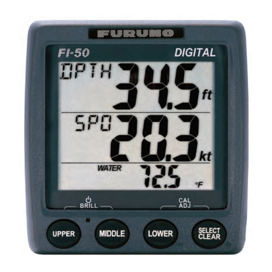
OPERATION The FI-503 Digital instrument provide depth, wind, boat speed and envi- ronmental information, on three separate displays. Various navigation alarms and distance counters are also provided. Operating Controls, Display Layout UPPER display (Depth and wind angle information and associated alarms) -
Page 9: Turning The Power On/Off
1. OPERATION Turning the Power On/Off To power the instrument, press the UPPER key. All LCD segments go on and off and then the last-used display appears. To power off the instrument, press the UPPER and MIDDLE keys to- gether. The timer appears and counts down from three seconds to one second, and then the power goes off. -
Page 10: Selecting A Display
1. OPERATION Selecting a Display Use the UPPER, MIDDLE and LOWER keys to select the item to display in the upper, middle and lower displays. Current depth DPTH Low apparent DPTH Shallow ° wind angle 18 0 SHALLOW 02 0 alarm alarm UPPER... - Page 11 1. OPERATION Upper display Display Function Display Function Current depth, in meters, Set deep anchor alarm. DPTH DPTH feet or fathoms. The alarms are released DEEP 02 0 when depth goes higher than threshold value. Set shallow alarm. The Apparent (or true) wind DPTH alarms are released angle, in degrees.
- Page 12 1. OPERATION Beaufort no. and wind speed Wind speed Wind speed Beaufort Beaufort 0-0.2 28-33 14.4-17.4 0.5-2.0 34-40 17.5-21.0 2.1-3.5 41-47 21.1-24.6 7-10 3.6-5.6 48-55 24.7-28.8 11-16 5.7-8.6 56-63 28.9-32.6 17-21 8.7-11.2 32.7-32.9 22-27 11.3-14.3 Lower display Display Function Display Function Air temperature, in °...
-
Page 13: Selecting Apparent Or True Wind Angle, Wind Speed
1. OPERATION Selecting Apparent or True Wind Angle, Wind Speed You can show wind angle and wind speed in apparent or true wind. The apparent wind is the actual flow of air acting upon a sail, or the wind as it appears to the sailor. -
Page 14: Alarms
1. OPERATION Alarms There are eight conditions which trigger audio and visual alarms: Shallow alarm, Deep alarm, Shallow anchor alarm, Deep anchor alarm, High ap- parent wind angle, Low apparent wind angle, Maximum true wind speed alarm, and Low true wind speed alarm. 1. - Page 15 1. OPERATION 2. If the selected alarm page shows “Off,” press and hold down the SELECT/CLEAR key until an alarm setting appears. 3. Press the LOWER and SELECT/CLEAR keys together to enable adjustment. The alarm setting starts flashing. 4. Press the LOWER key to lower the setting; the SELECT/CLEAR key to raise it.
-
Page 16: Timers
1. OPERATION Timers Three timers are provided on the lower display: • Count-up timer (stopwatch) • Count-down timer (two provided) Time is displayed in seconds or minutes, depending on counter values. Once you have set a timer, you can leave that page and select any other display. -
Page 17: Resetting Counters And Indications
1. OPERATION To stop or restart the timer, press the SELECT/CLEAR key momen- tarily. A short beep sounds when the timer is stopped or restarted. To stop and reset the timer to start value, press the SELECT/CLEAR key until you hear a long beep. The timer is stopped and reset to start value. -
Page 18: Maintenance, Troubleshooting
MAINTENANCE, TROUBLESHOOTING This chapter provides the information necessary for keeping your equip- ment in good working order. WARNING Do not open the equipment. Only qualified personnel should work inside the equipment. Preventive Maintenance Following the recommended procedures below will help maintain perfor- mance. -
Page 19: Troubleshooting
2. MAINTENANCE, TROUBLESHOOTING Troubleshooting If you feel the equipment is not functioning properly, follow the proce- dures in the table below to try to restore normal operation. If normal op- eration cannot be restored, do not attempt to check inside the cabinet. There are no user-serviceable parts inside. -
Page 20: Installation
Equipment Lists Standard supply Name Type Code No. Remarks Display Unit FI-503 Installation CP26-00600 000-011-744 1 set See packing list at end of Materials manual for details. Optional supply Name Type Code No. -
Page 21: Mounting
3. INSTALLATION Mounting The display unit can be installed two ways: surface mount (fixed at front panel or fixed from rear panel) and flush mount (optional kit required). This section covers surface mounting. For flush mounting, see the flush mounting instructions, issued separately. Surface mount 1: Fix instrument from front panel 1. - Page 22 3. INSTALLATION Surface mount 2: Fix instrument from rear panel 1. Using the template at the back of this manual, open a mounting hole in the installation site. 2. Insert studs (M3x40, 2 pcs., supplied) in the holes shown below. (Use only the studs supplied.) Insert stud here.
-
Page 23: Wiring
3. INSTALLATION Wiring For the service technician, detailed information about CAN bus wiring is on the FURUNO Tech-Net. See “Furuno CAN bus Network Design Guide” (TIE-00170-*). 3.3.1 Standalone configuration For standalone configuration the junction box is not necessary; connect the instrument directly to the power supply –... - Page 24 3. INSTALLATION 3.3.2 Multi-instrument configuration FI-50-CHAIN (0.3 m: Std, 1/5/10/20 m: Option) DISP. UNIT FI-501/502/FI-504/FI-505/FI-506/507 DISP. UNIT (Instruments can be connected FI-503 in any order.) Instruments chained FI-50-DROP-6M Cable as above (6 m, standard supply) Instruments chained as above JUNCTION BOX...
- Page 25 3. INSTALLATION Junction box (option) The junction box is required when connecting CAN bus network. This section covers wiring of the junction box. For how to mount the junction box, see its installation instructions, issued separately. 12VDC BACKBONE DROP DROP DROP 12 VDC CAN bus...
- Page 26 3. INSTALLATION Terminal resistor The illustration below show various system configurations and what units to activate the terminal resistor. Smart sensor+FI-50x Smart FI-50x Sensor Multiple FI-50 series instruments, FI-5002, drop cabling FI-50x FI-50x FI-50x FI-50x Drop cable FI-5002 Multiple FI-50 series instruments, FI-5002 FI-50x FI-50x FI-50x FI-50x FI-5002...
-
Page 27: Setting Up
3. INSTALLATION Turn on the terminal resistor in the junction box when the NMEA 2000 sensor(s) connected to it do not have a terminal resistor. Terminal Resistor OFF: For how to turn on the terminal resistor in a FI-50 series instrument, see page 24. - Page 28 3. INSTALLATION DPTH DPTH DPTH DPTH SHALLOW Depth unit Depth offset Depth response Shallow alarm Speed unit setting lock 0.01 Speed resolution WATER Temperature offset Speed adjustment UPPER WATER Temperature unit Log unit VMG response Speed response WSPD Wind speed response SOG response ANGS WSPD...
- Page 29 3. INSTALLATION 3. Use the LOWER and SELECT/CLEAR key to set value or select option. LOWER key: Decrement value. SELECT/CLEAR key: Increment value or select option. 4. To continue, press the UPPER key to select another menu item. 5. To save settings and restore normal operation, press the LOWER and SELECT/CLEAR keys together.
- Page 30 3. INSTALLATION Setup1 menu items Setting range or Default Display Function options setting Set speed adjustment. 0.30 - 2.50 1.00 (STW only) 1.00 Select log unit. sm (statute mile), km (kilometer), nm (nautical mile) Set response to speed change. 0 - 12 The lower the setting the faster the response.
- Page 31 3. INSTALLATION Setup1 menu items Setting range or Default Display Function options setting Set wind speed adjustment. 0.3 - 2.5 WSPD S 0 ° - 180 ° Set wind angle offset. ANGS P 1 ° - 179 ° Set wind speed response. The 0 - 12 lower the setting the faster the response.
- Page 32 3. INSTALLATION 2. Use the UPPER key to select a menu item. Each press of the key changes the menu item in the sequence shown below. xxxx* xxxx* beep brill SEtUP Software ver. no Software ver. no Key beep Auto brilliance Setup1 menu of CPU1 of CPU2...
- Page 33 3. INSTALLATION Setup2 menu items Default Display Function Options setting Adjust brilliance automatically ON, OFF with environment. brILL Enable/disable access to the ON, OFF setup1 menu. SEtUP Terminal resistor on/off. ON, OFF Turn on/off synchronization of Synchronize all FI-50 FI-50 series instruments. instruments having this setting.
-
Page 34: Specifications
FI-503 DIGITAL SPECIFICATIONS OF FI-503 DIGITAL GENERAL 1.1 Display Segment LCD 1.2 Display Content Depth, speed, wind angle, wind speed, timer, environmental, nav data, rudder angle 1.3 I/O Port CAN bus, 2 ports JUNCTION BOX (OPTION) 2.1 No. of I/O ports... - Page 36 OUTLINE NAME DESCRIPTIONS REMARKS ※1 前面パネルF TZ7580002A0 FRONT PANEL CODE NO. 000-167-885-10 ※1に貼付済み FURUNOロゴH3 PRE-ATTACHED TO ※1. 19-028-1502-0 FURUNO STICKER H3 CODE NO. 100-339-580-10 ハードカバーF TZ7580007AO COVER CODE NO. 000-167-887-10 フラッシュマウントツール TZ7580008AO FRAME CODE NO. 000-167-886-10 +ナベタッピンネジ 1シュ 3X20 SUS304 SELF-TAPPING SCREW CODE NO.
- Page 41 タッピンネジ用穴(4ヵ所) For tapping screws (4 pcs.) 寸切りボルト用穴(2ヵ所) For bolts (2 pcs.)
- Page 42 FI-50シリーズ 表示部 フラッシュマウント用型紙 FI-50 series Display unit Flush Mount Template...
Need help?
Do you have a question about the FI-503 and is the answer not in the manual?
Questions and answers