Advertisement
Advertisement

Subscribe to Our Youtube Channel
Related Manuals for Furuno FI-30


Summary of Contents for Furuno FI-30
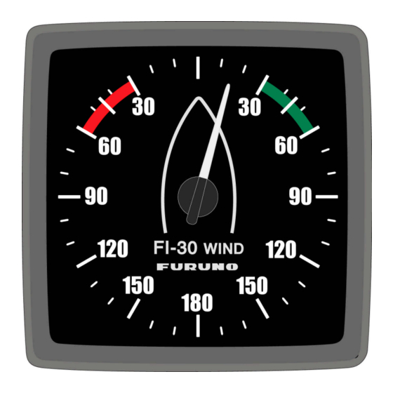
- Page 4 Digital instruments. For how to set these, see the manual for the digital instrument. The FI-30 Analog Wind, you may select it to display true or apparent wind angel. That setting is done from a digital instrument (see calibration code C52 in Multi Control...
-
Page 5: Table Of Contents
Part specification ... 1 Installation ... 4 Installing the instrument ... 5 Technical Data... 7 Maintenance ... 7 Drill template ... 8 Optional Accessories... 9 Abbreviations ... 10... -
Page 6: Part Specification
Part specification Items delivered with the Instrument Qty. Description FI-30 Analog instrument Instrument cover Adhesive drill template for instrument Operator’s Manual Instrument mounting pin bolts Instrument mounting nuts Connection back cover Silicon paste tube Plastic cable strap Cable protectors, 0.25 mm (0.1 inch) Cable protectors, 0.75 mm (0.3 inch) - Page 8 To get the most out of your new FURUNO product, please read through this manual carefully before you start your installation. Again, thank you for choosing FURUNO. If you see us at a show, stop by and say hello. Good luck and happy boating!
-
Page 9: Installation
Installation • The installation includes 6 major steps: 1. Read the operation manual. 2. Plan where to install the transducers and instruments. 3. Run the cables. 4. Install the transducers and instruments. 5. Take a break and admire your installation. 6. -
Page 10: Installing The Instrument
Installing the instrument Place the adhesive drill template on the desired location for the instrument. Drill the 2 holes using a 5 mm ( ") drill for the two pin bolts. Use a 63 mm (2½ ") hole saw to machine the clearance hole for the instrument connection socket. Remove the template. - Page 11 Apply silicon paste to the instrument connection pins at the back of the instrument. Press the jack plug onto the instrument pins. Press the cable in to the cable leads. Mount the connection back cover with the screw. Your instrument installation is done!
-
Page 12: Technical Data
Technical Data Instrument dimensions: Instrument cable: Power supply: The instrument is polarity protected. Power consumption: Analog Repeater: Digital Repeater: Temperature range: Weight: Maintenance Clean the instruments with mild soap solution only! Do not use high-pressure wash equipment! It is advisable to remove the instrument during long cold periods. Put silicone grease on each contact. -
Page 13: Drill Template
Drill template... -
Page 14: Optional Accessories
Equipment Lists INSTRUMENT SERIES PART # MODEL 000-041-864 FI-301 000-041-865 FI-301-SERVER 000-041-866 FI-301-SERVER/SENSOR MULTI CONTROL W/SERVER & SENSORS 000-041-867 FI-302 000-041-868 FI-302-SENSOR 000-041-869 FI-303 000-041-870 FI-303-SENSOR 000-041-871 FI-304 000-041-872 FI-305 000-041-873 FI-306 000-041-874 FI-307 000-041-875 FI-308 000-041-876 FI-309 000-041-877 FI-310 ACCESSORIES PART # MODEL... -
Page 15: Abbreviations
Abbreviations Boat Speed Bearing To Waypoint Celsius Fahrenheit KiloMetre KnoTS Miles per Hour Liquid Crystal Display RETurn Speed Over Ground TRiP Minus Plus...
Need help?
Do you have a question about the FI-30 and is the answer not in the manual?
Questions and answers