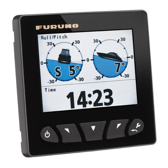
Furuno FI-70 Operator's Manual
Color instrument
Hide thumbs
Also See for FI-70:
- User handbook manual (20 pages) ,
- User handbook manual (20 pages) ,
- Operator's manual (98 pages)
Table of Contents
Advertisement
Quick Links
Advertisement
Table of Contents
Troubleshooting

Related Manuals for Furuno FI-70


Summary of Contents for Furuno FI-70
- Page 1 OPERATOR'S MANUAL COLOR INSTRUMENT FI-70 Model www.furuno.com...
- Page 2 ・FURUNO Authorized Distributor/Dealer 9-52 Ashihara-cho, Nishinomiya, 662-8580, JAPAN A : JAN 2015 Printed in Japan All rights reserved. Pub. No. OME-72810-A ( GREG ) FI-70 0 0 0 1 9 0 0 6 2 1 0...
-
Page 3: Important Notices
How to discard a used battery Some FURUNO products have a battery(ies). To see if your product has a battery, see the chapter on Maintenance. Follow the instructions below if a battery is used. Tape the + and - terminals of battery before disposal to prevent fire, heat generation caused by short circuit. - Page 4 Standard Steering Fire or electrical shock can result Compass Compass if water leaks into the equipment. FI-70 0.30 m 0.30 m Immediately turn off the power IF-NMEAFI 0.30 m 0.30 m at the switchboard if water leaks into the equipment.
-
Page 5: Table Of Contents
TABLE OF CONTENTS FOREWORD ........................v SYSTEM CONFIGURATION ..................vi EQUIPMENT LISTS....................... vii OPERATION AND CONTROLS OVERVIEW............1-1 1.1 Controls ........................1-1 1.2 How to Turn the Power On/Off ...................1-1 1.3 How to Adjust the Screen Brilliance ................1-2 1.4 Menu Overview......................1-3 1.5 How to Turn Key Beeps On/Off ..................1-4 1.6 How to Adjust the Panel Dimmer (Control Key Panel Backlights)......1-4 1.7 Screen Categories and Page Setup ................1-5 1.7.1... - Page 6 MAINTENANCE, TROUBLESHOOTING...............6-1 6.1 Preventive Maintenance..................... 6-1 6.2 Troubleshooting ......................6-2 6.3 Alarm Log........................6-2 6.4 Engine Error Icons ..................... 6-4 6.5 How to Diagnostically Test the FI-70 ................. 6-5 6.5.1 Self test ......................6-5 6.5.2 Keyboard test ....................6-6 6.5.3 Screen test .....................
-
Page 7: Foreword
FOREWORD A Word to the Owner of the FI-70 Congratulations on your choice of the FURUNO FI-70 Color Instrument. We are confident you will see why the FURUNO name has become synonymous with quality and reliability. Since 1948, FURUNO Electric Company has enjoyed an enviable reputation for quality marine electronics equipment. -
Page 8: System Configuration
SYSTEM CONFIGURATION Analog sensors Wind Transducer FI-5001/L Speed/Temp. Sensor Tank gauge ST-02MSB/ST-02PSB Color Instrument FI-70 (Maximum 11 units) Analog NMEA Data Converter IF-NMEAFI 12 VDC CAN bus/NMEA2000 sensors 15 VDC T-connector Junction Box Junction Box (option) FI-5002 FI-5002 CAN bus/NMEA2000 Backbone... -
Page 9: Equipment Lists
EQUIPMENT LISTS Standard Supply Name Type Code No. Remarks Color Instrument FI-70 Includes soft cover. Installation Materials CP26-02000 000-027-046 Contains CP26-02001 installation materials. Optional Supply Name Type Code No. Remarks Analog NMEA IF-NMEAFI Data Converter Wind FI-5001 Transducer FI-5001L Junction Box... - Page 10 EQUIPMENT LISTS This page is intentionally left blank. viii...
-
Page 11: Operation And Controls Overview
Press and hold the Power/Brill key to turn the FI-70 off. The message "Turning OFF in 3 seconds" is displayed. Hold the key for three seconds. Early release of the Power/ Brill key will abort the shutdown. -
Page 12: How To Adjust The Screen Brilliance
Press the function key to switch between Day and Night modes. Press function key to switch between modes. Day Mode Night Mode Note: When the FI-70 is subjected to undue heat, the brilliance may automatically darken. This is designed to reduce heat stress and is not a malfunction. -
Page 13: Menu Overview
1. OPERATION AND CONTROLS OVERVIEW Menu Overview 1. Press the Menu/Back key to display the main menu. The main menu contents change according to the current category (See section 1.7 for more information on categories). In the example below, the wind category is displayed. Category specific menu items are Wind Speed... -
Page 14: How To Turn Key Beeps On/Off
Displays a list showing the sensors currently set in the [Data Source] menu. [System] Change the FI-70 settings. (See chapter 4 for more information.) For category specific menus, see the appropriate category in chapter 2. How to Turn Key Beeps On/Off 1. -
Page 15: Screen Categories And
1. OPERATION AND CONTROLS OVERVIEW Screen Categories and Page Setup The FI-70 can display the information categories shown in the figures below, provided a sensor for the appropriate information is connected. 30min 30min 4300 4300 x1000 4400 4400 º Eng. Temp. -
Page 16: How To Change The Displayed Page
1.7.1 How to change the displayed page The FI-70 can display up to seven different pages of information. Use the software keys to change pages backwards and forwards between the pages. The number of the current page is displayed as a large numeral in the center of the screen for three seconds after the page is displayed. -
Page 17: How To Set Up Pages
1. OPERATION AND CONTROLS OVERVIEW 1.7.2 How to set up pages The FI-70 is capable of displaying seven pages of category information. The procedure below outlines how to set up a page. 1. Press the Menu/Back key to display the main menu. - Page 18 1. OPERATION AND CONTROLS OVERVIEW 3) Press the software keys to select the appropriate data to display, then press the function key. Depth Depth is shown on graph W Temp. Water temperature is shown on graph A Temp. Atmospheric temperature is shown on graph A Press.
-
Page 19: Display Categories And Category Specific Menus
Displays the current heading. HDG Avg.* Displays the average heading. HDG Tack Displays the projected heading on next tack. *: The average is calculated from when the FI-70 is turned on. All calculations are reset when the power is turned off. -
Page 20: Speed Category
Displays Velocity Made Good (VMG). Note: VMG is unavailable in SOG mode. *: The average and maximum values are calculated from when the FI-70 is turned on. All calculations for average and maximum are reset when the power is turned off. -
Page 21: Engine Category
NOTE: Data shown in the engine category is input from engine sensors. Always check any NOTE: Data shown in the engine category is input from engine sensors. Always check any malfunction at the engine, do not rely solely on the FI-70 indications. malfunction at the engine, do not rely solely on the FI-70 indications. -
Page 22: Graph Category
2. DISPLAY CATEGORIES AND CATEGORY SPECIFIC MENUS Graph Category 30min 30min 30min 30min 4300 4300 4300 4300 Depth Depth 4256 4256 4400 4400 30min 30min 4400 4400 1000 1000 Depth Depth A Press. A Press. 4303 4303 1003 1003 4500 4500 The graph category displays preselected sensor data in graph format. -
Page 23: Highway Category
2. DISPLAY CATEGORIES AND CATEGORY SPECIFIC MENUS Highway Category Destination/Waypoint name WAYPOINT Destination/Waypoint mark Own ship mark 0.05 Press the function key to change data displayed. The highway display provides a graphic presentation of your boat’s track along the intended course, toward a waypoint. Press the function key to cycle through the following data on the Highway display: Displayable data Description... -
Page 24: Timer Category
2. DISPLAY CATEGORIES AND CATEGORY SPECIFIC MENUS Timer Category Time Time 15:00 15:00 00:00 00:00 Trip Countdown Timer1 Countdown Timer2 Time 00:00 Countdown Timer 00:00 Lap time Trip meter Trip Countup Timer Countup Timer The Timer category has three available timers to select from, as indicated in the figure above. -
Page 25: How To Adjust The Timers
2. DISPLAY CATEGORIES AND CATEGORY SPECIFIC MENUS 2.7.2 How to adjust the timers 1. With the timer screen displayed, press the function key to show the [Func] key indications. The left software key indication is blank for the [Countup] timer. Setup Start Reset... -
Page 26: Wind Category
*: True Wind and Apparent Wind may be switched from the menu. See section 4.3 for details. The average and maximum values are calculated from when the FI-70 is turned on. All calculations for average and maximum are reset when the power is... -
Page 27: Ais Category
• [North Up] - Displays the targets and own ship with North oriented upwards. Note: The AIS category is a simplified AIS, with limited function and capacity. Only Class A and Class B AIS targets are displayed. Do not rely solely on the FI-70 indications for information about nearby targets. -
Page 28: How To Display Ais Target Details
Press the right software key to cycle through the targets, in order, from farthest to closest. 3. Press the function key to select a target and display its details. AIS details (Page 1) AIS details (Page 2) Target vessel’s name Furuno Furuno Range to Target’s MMSI ID MMSI: 0123456789 RNG: target Target’s Call Sign... -
Page 29: Custom Box Category
2. DISPLAY CATEGORIES AND CATEGORY SPECIFIC MENUS 2.10 Custom Box Category Depth W Temp. 3855 3855 º COG M º 42.5 42.5 POSN º º 37.145’N 37.145’N º º 29.108’W 29.108’W The Custom Box category allows you to customize the display, dividing the display area with up to 6 boxes. -
Page 30: How To Customize The Data Boxes
2. DISPLAY CATEGORIES AND CATEGORY SPECIFIC MENUS 2.10.1 How to customize the data boxes With the Custom Box screen displayed, the key indications show "Edit" as the function key function. 1. Press the function key to begin customizing the boxes. The selected box is highlighted in blue. -
Page 31: How To Resize Data Boxes
2. DISPLAY CATEGORIES AND CATEGORY SPECIFIC MENUS 2.10.2 How to resize data boxes 1. With the Custom Box category displayed, press the function key. 2. Press the software keys to highlight the data box to be resized, then press the function key. -
Page 32: Data Which May Be Displayed In Custom Boxes
Blank data box 11 : The average and maximum values are calculated from when the FI-70 is turned on. All calculations for average and maximum are reset when the power is turned off. : These items are shown in simplified format when displayed in the custom data boxes. -
Page 33: Alarms
In the case of multiple alarms, press the function key several times to clear the pop-ups. All alarms which have occurred since the FI-70 was turned on are stored in the [Alarm Log]. See "Alarm Log" on page 6-2.) How to Set the Audio Alert Pattern The audio alert pattern can be set for each alarm using the following procedure. -
Page 34: Stw Alarm And Sog Alarm
3. ALARMS STW Alarm and SOG Alarm The STW and SOG alarms set a high speed or low speed alarm threshold. When the vessel speed goes over the high speed threshold, or below the low speed threshold, the alarm is activated. 1. -
Page 35: Wind Speed/Direction Alarms
3. ALARMS Wind Speed/Direction Alarms 3.3.1 TWS alarm The TWS alarm sets a true wind speed alarm threshold. When the TWS goes over the set threshold, the alarm is activated. 1. Access the [Alarms] menu, using the procedure outlined on page 3-1. 2. -
Page 36: Trip Alarm
Trip Alarm The trip alarm is activated when the total distance traveled reaches the set threshold. The total distance traveled is calculated from the moment the FI-70 is powered for the first time. This distance is stored in the trip log. -
Page 37: Depth Alarm
7. Press the Menu/Back key twice to close the menu. Low Voltage Alarm The low voltage alarm is activated when the input voltage to the FI-70 drops below the set threshold. 1. Access the [Alarms] menu, using the procedure outlined on page 3-1. -
Page 38: Water Temperature Alarm
3. ALARMS Water Temperature Alarm The water temperature alarm warns you when the temperature goes over or under the set threshold. The average temperature may also be used as a threshold and is calculated over one minute intervals. 1. Access the [Alarms] menu, using the procedure outlined on page 3-1. 2. -
Page 39: Engine Alarms
3. ALARMS Engine Alarms The engine alarm is activated when the FI-70 receives information containing errors or alarms from the engine. The indicators shown in the table below are normally displayed in gray when the engine category is selected. When an alarm is active, the corresponding indicator flashes and the color changes to an orange-red. -
Page 40: Anchor Alarm
3. ALARMS Anchor Alarm The anchor alarm activates when the vessel exceeds the selected distance from the point at which the alarm was set, or the depth is higher/lower than the depth threshold setting. This alarm is useful when at a standstill or not at the helm. Where Anchor Alarm Where Anchor Alarm Gray... -
Page 41: Cpa/Tcpa Alarms
3. ALARMS 3.10 CPA/TCPA Alarms The CPA (Closest Point of Approach) and TCPA (Time to Closest Point of Approach) alarms activate when the distance between your vessel and an AIS target is smaller than the threshold set. This alarm is used as an aid to avoid collision. Note: The CPA and TCPA alarms are a navigational aid only. - Page 42 3. ALARMS This page is intentionally left blank. 3-10...
-
Page 43: System Menu
In the example above, the network contains a TZtouch2 unit and four FI-70 units. Some settings, such as data source and offsets, made on a TZtouch2 unit (or FI-70 set as a Master unit) within the network may be passed onto the slave units on the same network. -
Page 44: How To Adjust The Sharing Level
Description [Stand Alone] Disables sharing of settings. [Slave] TZtouch2 unit (or FI-70 set as a Master unit) settings are passed to the FI-70 unit. [Master] This unit’s settings are passed to all slave FI-70 units. Where a TZtouch2 unit is in the same network, the TZtouch2 unit is automatically assigned as the [Master] and this option is not available. -
Page 45: How To Share Language And Brilliance Settings Between Fi-70S
Group B Group A Group B There are three groupings available: A, B and C. To assign a group to a FI-70 unit, do the following: 1. Access the [System] menu using the procedure outlined on page 4-1. 2. Press the software keys to scroll through the menu and select [Group], then press the function key. -
Page 46: How To Set The Display Format
4. SYSTEM MENU How to Set the Display Format The format in which date, time and other displayed items are shown may be set from the [Display Format] menu. The [Display Format] is accessed from the [System] menu. Display Format HDG/COG Ref: Magnetic Mag. -
Page 47: How To Adjust The Engine Settings
4. Press the software keys to select the appropriate number of engines aboard the vessel, then press the function key. The FI-70 is able to display up to three engines’ data. The [Number of Engine] setting also changes the [Engine Setup] menu layout, as shown in the figure below. - Page 48 6. Press the Menu/Back key twice to close the menu. How to update the engine list [Engine Refresh] When an engine is removed for service, or when the FI-70 otherwise loses connection with the engines, it is important to update the engine list. The [Engine Refresh] function checks the CAN bus/NMEA2000 network for connected engines and updates the engine list.
-
Page 49: How To Set The Displayed Scale Range
3. Press the software keys to select the scale range you wish to adjust. Note: The table below lists the available options based on default unit of measurement settings. Options available on your FI-70 unit may be different. Menu Item... -
Page 50: How To Set Up The If-Nmeafi (Option)
4. SYSTEM MENU How to Set Up the IF-NMEAFI (Option) The optional IF-NMEAFI is required when inputting data from analog NMEA equipment to the FI-70. Set the IF-NMEAFI up as follows. 4.6.1 IF-NMEAFI menu settings 1. Access the [System] menu using the procedure outlined on page 4-1. -
Page 51: How To Test The If-Nmeafi
4. SYSTEM MENU 4.6.2 How to test the IF-NMEAFI 1. Access the [System] menu using the procedure outlined on page 4-1. 2. Press the software keys to select [IF-NMEAFI], then press the function key. 3. [Select IF] is already selected, press the function key. 4. -
Page 52: How To Interpret The I/O Setup Menu
Select [CAN Bus Refresh] (NMEA2000 Refresh*) to refresh the items displayed in the [Incoming PGN] and [Device List] screens. The lists should be refreshed when devices are added or removed from the same network as this FI-70 unit. *: The menu name may change depending on your software version. -
Page 53: How To Set The Data Source(S)
6. Press the Menu/Back key twice to close the menu. Automatic data source switching The FI-70 can automatically switch data sources if data from the set source is interrupted or lost, provided there is a suitable sensor connected to the same network as the FI-70. -
Page 54: How To Adjust (Calibrate) Incoming Data
4. SYSTEM MENU How to Adjust (Calibrate) Incoming Data Use the [Data Calibration] menu to adjust offsets for data input to the FI-70. 1. Access the [System] menu using the procedure outlined on page 4-1. 2. Press the software keys to select [Data Calibration], then press the function key. -
Page 55: How To Change The Language
4. SYSTEM MENU 4.10 How to Change the Language To change the language, do the following: 1. Access the [System] menu using the procedure outlined on page 4-1. 2. Press the software keys select [Language], then press the function key. 3. -
Page 56: Other Items
Note: Do not use this mode when the vessel in underway. Diagnostic The [Diagnostic] menu may be used to conduct a self-test of FI-70, test the keys or test the screen. For more information on the [Diagnostic] menu, see "How to Diagnostically Test the FI-70"... -
Page 57: Installation And Initial Settings
• Referring to the outline drawing at the back of this manual, leave sufficient space around the FI-70 to allow for service and maintenance. • When the FI-70 is not in use, fit the soft cover (supplied) to the FI-70. Leave sufficient room surrounding the FI-70 to allow fitting of the soft cover. -
Page 58: Flushmount
FI-50 series instrument was installed to allow use of the mounting hole. 1. Using the supplied template, cut a hole in the mounting location. 2. Fit the stud bolts (M340, 2 pcs, supplied) to the rear of the FI-70. Note: Do not use tools to fit or insert the stud bolts. -
Page 59: Frontmount (Option)
Care must be taken not to fill the soft cover locking points on the FI-70. (Eight in total, four at the top rear of the unit and four at the bottom rear of the unit, see the figure below for reference.) Silicone seepage into the locking points prevents the soft cover from fitting correctly. - Page 60 5. INSTALLATION AND INITIAL SETTINGS How to remove a frontmounted FI-70 To remove the FI-70 from the frontmount panel, release the pin holders at the back of the panel, then remove the FI-70. Forced removal may damage the pin holders, pins, frontmount panel or the FI-70 unit.
-
Page 61: Wiring
Using the supplied cable assembly, connect the FI-70 to the CAN bus/NMEA2000 network backbone. The FI-70 must be on the same network as the sensors you wish to connect to. Power is also supplied via the CAN bus/NMEA2000 backbone to the FI-70. -
Page 62: How To Connect To The Wind Transducers Fi-5001/L
1. Fabricate a grounding cable (IV-1.25sq., local supply) with a close-end terminator (local supply). 2. Connect the close-end terminator to the rear of the FI-70, as indicated in the figure on the previous page. 3. Connect the loose end of the grounding cable to the ship’s ground. -
Page 63: How To Connect To The Fi-5002 Junction Box (Option)
5.2.3 How to connect to the FI-5002 Junction Box (Option) When using the FI-5002, connect the NMEA2000 port of the FI-70 to the FI-5002 internal MC connectors (CN3 thru CN5). For FI-5002 installation instructions, refer to the Installation Manual (C72-00702). -
Page 64: Terminator Resistors
5. Pull the wire to confirm connection. MC connector 5.2.4 Terminator resistors Terminator resistors are required to close off the network ends, completing the network. The following FURUNO terminator resistors are available: Part name Type Code No. Remarks NMEA LTWMN-05AMMT-SL8001... -
Page 65: Input/Output
Jumper block settings : Resistor is disconnected. (OFF) CN3 CN4 CN4 CN5 CN5 CN2 : Resistor is connected. (ON) Input/Output PGNs The FI-70 can input/output the following PGNs. Input PGNs Description Description 059904 ISO Request 060928 ISO Address Claim 061184... -
Page 66: Post Installation Initial Settings (Initialization Menu)
After mounting and wiring are completed, when the CAN bus/NMEA2000 network is turned on, the FI-70 will start up. If this is the first time the FI-70 has been powered, the [Initialization] menu is displayed. Set the language, units of measurement and your ship type in this menu. - Page 67 11. Press the software keys to select the number of engines on the vessel, then press the function key. The FI-70 may display up to three engines’ data. The menu items displayed in the [Engine Setup] menu change according to the number of engines selected here.
- Page 68 5. INSTALLATION AND INITIAL SETTINGS 12. Select the engine to be used as the data source. Note: Engine numbers are assigned at each engine. Where [Number of Engine] is set to [1] • [Engine Assign]: Select the engine number to be displayed. Where [Number of Engine] is set to [2] •...
-
Page 69: Maintenance, Troubleshooting
MAINTENANCE, TROUBLESHOOTING This chapter provides necessary information for keeping your equipment in good working order. NOTICE WARNING Do not apply paint, anti-corrosive Do not open the equipment. sealant or contact spray to coating or plastic parts of the equipment. Only qualified personnel should work inside the equipment. -
Page 70: Troubleshooting
FI-70. Alarm Log The [Alarm Log] stores all alarms released after power is applied to the FI-70. The log is cleared when the FI-70 is turned off. To display the [Alarm Log], press the Menu/Back key, select [Alarm Log], then press the function key. - Page 71 6. MAINTENANCE, TROUBLESHOOTING Alarm code Pop-up message Reason/Possible remedy Check Engine. Engine warning/alarm. Check the engine and engine sensor. Low Oil Pressure. Oil pressure warning/alarm. Check the oil pressure and pressure sensor. Over Temperature. Coolant high temperature warning/alarm. Check the coolant temperature and temperature sensor.
-
Page 72: Engine Error Icons
6. MAINTENANCE, TROUBLESHOOTING Engine Error Icons When the FI-70 receives error information from a connected engine, the data display for that engine shows a flashing orange-red icon for the error. Each icon and its meaning are shown in the table below. -
Page 73: How To Diagnostically Test The Fi-70
6. MAINTENANCE, TROUBLESHOOTING How to Diagnostically Test the FI-70 The FI-70 has a [Diagnostic] menu where you may check the keyboard, screen and also conduct a self-test on the FI-70. 1. Press the Menu/Back key to open the main menu. -
Page 74: Keyboard Test
6. MAINTENANCE, TROUBLESHOOTING 6.5.2 Keyboard test The keyboard test allows you to check each key is functioning normally. Note: Alarms are not displayed during this test. Keyboard Test Push MENU key three times to return. Press any key. If the key is functioning normally, the color for that key is changed to blue. -
Page 75: Appendix 1 Menu Tree
APPENDIX 1 MENU TREE Menu/Back key Menu/Back key Default settings shown in bold italic. Displayed page-based menus (See Pages 14 to 15) Alarm (OFF, Low, High; 0.0kn to 999.9kn, 10.0kn) STW Alarm Alarms Buzzer (Short, Middle, Long, Continue) SOG Alarm Alarm (OFF, Low, High;... - Page 76 APPENDIX 1 MENU TREE (Continued from previous page) Engine Setup Number of Engine (1 to 3, 1) Engine Assign (1 to 4, 1) Where [Number of Engine] is set to [1] Engine PORT (1 to 4, 1) Where [Number of Engine] is set to [2] or [3] Engine STBD (1 to 4, 2) Where [Number of Engine] is set to [2] or [3] Engine Center (1 to 4, 3) Where [Number of Engine] is set to [3] Engine Refresh...
- Page 77 APPENDIX 1 MENU TREE Compass Compass Compass Press the Menu/Back key Heading Offset(HDG)(180° to W179°, 0°) Press the Menu/Back key Adust(STW)(0.30 to 2.50, 1.00) STW Alarm Alarm (OFF, Low, High: 0.0 to 999.9kn, 10.0kn) Buzzer (Short, Middle, Long, Continue) Press the Menu/Back key SOG Alarm Alarm (OFF, Low, High: 0.0 to 999.9kn, 10.0kn) Buzzer (Short, Middle, Long, Continue)
- Page 78 APPENDIX 1 MENU TREE Press the Menu/Back key Orientation (North Up, Heading Up) CPA TCPA Alarm Alarm (OFF,ON) CPA (0 to 6.00NM, 0.00NM) TCPA (30sec, 1min, 2min, 3min, 4min, 5min, 6min, 12min) Buzzer (Short, Middle, Long, Continue) Custom Box Custom Box Custom Box Custom Box Custom Box...
-
Page 79: Specifications
FURUNO FI-70 SPECIFICATIONS OF COLOR INSTRUMENT FI-70 GENERAL Screen 4.1-inch color TFT LCD, QVGA (320 x 240) Backlight 8 steps Buzzer 55 dB or more Display mode Analog meter, Graph, Highway, Race timer, simplified AIS, Data box Display data Ship’s speed, Wind speed/direction, Bearing, Track, Nav data,... -
Page 80: Packing Lists
PACKING LIST 26AL-X-9851 -2 FI-70 N A M E DESCRIPTION/CODE № O U T L I N E Q'TY ユニット UNIT カラーインスツルメント FI-70 COLOR INSTRUMENT 000-027-045-00 工事材料 INSTALLATION MATERIALS ケーブル組品 M12-05BM+05BF-060 CABLE ASSEMBLY 001-105-770-10 工事材料 CP26-02001 INSTALLATION MATERIALS 001-336-500-00 図書 DOCUMENT フラッシュマウント型紙... - Page 81 001-336-500-00 26AL-X-9401 CODE NO. TYPE CP26-02001 工事材料表 INSTALLATION MATERIALS 番 号 名 称 型名/規格 数量 略 図 用途/備考 Q'TY OUTLINE NAME DESCRIPTIONS REMARKS Fマウントスポンジ 26-008-1011-0 F MOUNT SPONGE CODE NO. 100-394-750-10 ミガキ丸平座金 M3 SUS304 FLAT WASHER CODE NO. 000-167-453-10 バネ座金 M3 SUS304 SPRING WASHER CODE NO.
-
Page 86: Index
INDEX AIS target details........2-10 Factory default restore ......4-14 Alarms FI-70 shared settings .........4-3 Alarm codes ..........6-2 Alarm list ..........6-2 Group settings..........4-3 Alarm log ..........6-2 Anchor............3-8 How to change pages ........1-6 audio pattern ..........3-1 CPA/TCPA ..........3-9 Crosswind ..........3-3 I/O Setup menu ........4-10 Depth............3-5... - Page 87 INDEX Troubleshooting ........6-2 Units of measurement ......4-13 Wiring ............5-5 CAN bus definition ........5-5 connection ..........5-5 FI-5001/L connection ......5-6 FI-5002 cable fabrication......5-8 FI-5002 connection ......... 5-7 grounding ..........5-6 NMEA2000 port........5-5 terminal resistors ........5-8 IN-2...
Need help?
Do you have a question about the FI-70 and is the answer not in the manual?
Questions and answers