Furuno FI-70 User Handbook Manual
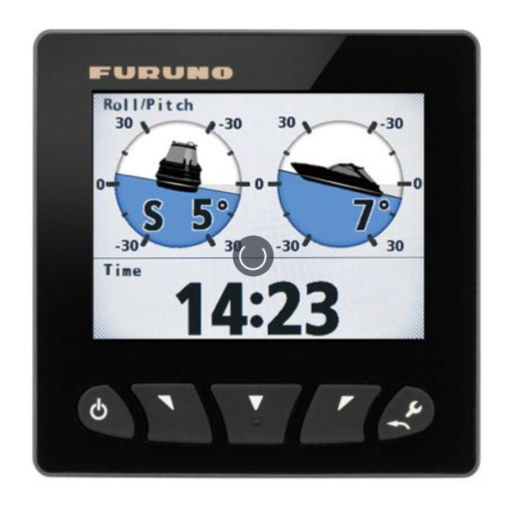
Color instrument
Hide thumbs
Also See for FI-70:
- Operator's manual (87 pages) ,
- User handbook manual (20 pages) ,
- Operator's manual (98 pages)
Table of Contents
Advertisement
Quick Links
Download this manual
See also:
Operator's Manual
COLOR INSTRUMENT
This User Handbook covers the basic installation and operation of the FI-70. For
detailed information, refer to the Operators Manual, accessible from the URL or quick
response code to the right. URL: http://www.furuno.com/en/support/manuals/terms
In the search box at the top of the screen, enter "FI-70", then click "Search".
SAFETY INSTRUCTIONS............................................................................................................ 1
UNIT OVERVIEW, FUNCTIONS .................................................................................................. 2
INSTALLATION ............................................................................................................................ 2
Flushmount Installation ........................................................................................................ 2
Frontmount Installation (Option)........................................................................................... 3
WIRING ........................................................................................................................................ 4
Network Connection ............................................................................................................. 4
Grounding ............................................................................................................................ 4
INITIAL SETTINGS....................................................................................................................... 5
How to Select a Language and Units of Measurement ........................................................ 5
How to Set Up Own Ship Type ............................................................................................ 5
How to Select the Data Source ............................................................................................ 6
How to Set Up the IF-NMEAFI (option) ................................................................................ 6
STANDARD OPERATION............................................................................................................ 7
How to Adjust Brilliance and Change Between Day/Night Modes ....................................... 7
How to Change Pages ......................................................................................................... 7
How to Adjust Page Settings (Displayed Category) ............................................................. 7
Page List by Category.......................................................................................................... 8
HOW TO EDIT THE CUSTOM BOXES........................................................................................ 9
How to Adjust Data Box Displayed Data .............................................................................. 9
How to Adjust Data Box Size Settings ............................................................................... 10
SHARING AND GROUPS .......................................................................................................... 11
Network Settings ................................................................................................................ 11
Language and Brilliance Sharing Between FI-70 Units...................................................... 11
MENU TREE............................................................................................................................... 12
Main Menu ......................................................................................................................... 12
Category Specific Menus ................................................................................................... 14
OUTLINE DRAWINGS .........................................................................................................D-1
INTERCONNECTION DIAGRAM........................................................................................ S-1
All brand and product names are trademarks, registered trademarks or service marks of their respective holders.
USER HANDBOOK
TABLE OF CONTENTS
www.furuno.com
FI-70
Model
Advertisement
Table of Contents

Related Manuals for Furuno FI-70


Summary of Contents for Furuno FI-70
-
Page 1: Table Of Contents
Operators Manual, accessible from the URL or quick response code to the right. URL: http://www.furuno.com/en/support/manuals/terms In the search box at the top of the screen, enter “FI-70”, then click “Search”. TABLE OF CONTENTS SAFETY INSTRUCTIONS......................1 UNIT OVERVIEW, FUNCTIONS .................... -
Page 2: Safety Instructions
Standard Steering Fire or electrical shock can result Compass Compass if water leaks into the equipment. FI-70 0.30 m 0.30 m Immediately turn off the power at the switchboard if water leaks About the TFT LCD into the equipment. -
Page 3: Unit Overview, Functions
Using the supplied template, mark and cut a hole in the installation location. Butterfly Fit the supplied stud bolts (M3×40, 2 pcs) to the rear of the FI-70. Note: Do not use tools to fit or insert the stud bolts. -
Page 4: Frontmount Installation (Option)
Set the FI-70 into the frontmount panel, using the snap pins and snap pin slots as guides. Push the FI-70 into the frontmount panel until a “click” sound is made, indicating that the FI-70 is now secure in the panel. -
Page 5: Wiring
Grounding Grounding Use the included cable to connect the Fabricate a ground wire (IV-1.25sq., local supply) with FI-70 NMEA2000 port to the CAN bus a closed-end terminal. (NMEA2000) network backbone. Unfasten the ground terminal screw, then referring to the figure below, connect the ground wire to the ground terminal of the FI-70. -
Page 6: Initial Settings
After mounting and wiring are completed, when the CAN bus (NMEA2000) network is turned on, the FI-70 will start up. If this is the first time the FI-70 has been powered, the [Initialization] menu is displayed. Set the language, units of measurement and your ship type in this menu. -
Page 7: How To Select The Data Source
How to Set Up the IF-NMEAFI (option) When connecting analog sensors such as the wind transducer FI-5001/L, the optional IF-NMEAFI data converter must be used as between the sensor and the FI-70. When using the IF-NMEAFI, set up the IF-NMEAFI using the following procedure. -
Page 8: Standard Operation
FI-70 units on the same network may be grouped, allowing the brilliance settings and language settings to be shared. For example, if one FI-70 in Group A has the brilliance setting adjusted, all FI-70 units in Group A are also adjusted. For further details on groups, see page 11. -
Page 9: Page List By Category
Gear Oil T (Gear oil temperature) Gear Oil P (Gear oil pressure) Boost Note: Data shown in the engine category is input from engine sensors. Always check any malfunction at the engine, do not rely solely on the FI-70 indications. Rudder Rudder Graph Graph... -
Page 10: How To Edit The Custom Boxes
WPT (Waypoint co-ordinates) customizable. Only Class A and Class B AIS targets are RNG (Range to waypoint) displayed. Do not rely solely on the FI-70 BRG (Bearing to waypoint) indications. HOW TO EDIT THE CUSTOM BOXES How to Adjust Data Box Displayed Data... -
Page 11: How To Adjust Data Box Size Settings
Wind Chill Dew Point Voltage Volts Disable display for this box. *: The average and maximum values are calculated from when the FI-70 is turned on. All calculations for average and maximum are reset when the power is turned off. -
Page 12: Sharing And Groups
As shown in the example figure below, adjusting the brilliance settings for one FI-70 unit in Group A changes the brilliance settings for all FI-70 units in the same group. While one FI-70 unit in a group has the brilliance adjusted or the language changed, all other FI-70 units in the same group cannot have the brilliance or language settings adjusted. -
Page 13: Menu Tree
MENU TREE Main Menu Main Menu Main Menu Default settings shown in bold italic. Menu/Back key Menu/Back Displayed page-based menus (See Pages 14 to 15) Alarm (OFF, Low, High; 0.0kn to 999.9kn, 10.0kn) STW Alarm Alarms Buzzer (Short, Middle, Long, Continue) SOG Alarm Alarm (OFF, Low, High;... - Page 14 (Continued from previous page) Engine Setup Number of Engine (1 to 3, 1) Engine Assign (1 to 4, 1) Where [Number of Engine] is set to [1] Engine PORT (1 to 4, 1) Where [Number of Engine] is set to [2] or [3] Engine STBD (1 to 4, 2) Where [Number of Engine] is set to [2] or [3] Engine Center (1 to 4, 3) Where [Number of Engine] is set to [3] Engine Refresh...
-
Page 15: Category Specific Menus
Category Specific Menus Compass Compass Compass Compass Compass Press the Menu/Back key Heading Offset(HDG)(180° to W179°, 0°) Press the Menu/Back key Adust(STW)(0.30 to 2.50, 1.00) STW Alarm Alarm (OFF, Low, High: 0.0 to 999.9kn, 10.0kn) Buzzer (Short, Middle, Long, Continue) Press the Menu/Back key SOG Alarm Alarm (OFF, Low, High: 0.0 to 999.9kn, 10.0kn) - Page 16 Press the Menu/Back key Orientation (North Up, Heading Up) CPA TCPA Alarm Alarm (OFF,ON) CPA (0 to 6.00NM, 0.00NM) TCPA (30sec, 1min, 2min, 3min, 4min, 5min, 6min, 12min) Buzzer (Short, Middle, Long, Continue) Custom Box Custom Box Custom Box Custom Box Custom Box Press the Menu/Back key Heading* (See previous page)
- Page 20 PUB. NO. E72-01403-A (1501, GREG) FI-70 00019006610...
Need help?
Do you have a question about the FI-70 and is the answer not in the manual?
Questions and answers