Table of Contents
Advertisement
Quick Links
Advertisement
Table of Contents

Related Manuals for Furuno FI-303


Summary of Contents for Furuno FI-303
- Page 4 Introduction Thank you for choosing FI-30 Wind Data instrument. We are convinced that you will appreciate all the valuable information either you are a cruiser or a racer. It is important that you are following this instruction regarding installation and operation. If the instrument are to be used in a Nexus Network, there are some systems settings that are dependent on where the transducers are installed, i.e.
-
Page 5: Table Of Contents
Part specifications...6 Installation...8 Installing the instrument...9 Installing cable ...11 Connections in Nexus Network...11 Connection of log transducer...12 First start (only in a Nexus Network) ...13 Initialising the instrument ...13 Re-initialising the instrument...13 Operation...14 About this manual ...14 How to use the 5 push-buttons ...15 5.2.1 PAGE...15 5.2.2... - Page 6 C31 True or magnetic course ... 28 6.3.2 C32 Magnetic deviation ... 28 6.3.3 C33 Reference for Compass, static or GPS... 28 C50 Wind Settings ... 29 6.4.1 C51 Network setting of true or apparent Wind angle ... 29 6.4.2 C52 Unit for Wind speed ...
-
Page 7: Part Specifications
Part specifications FI-30 Wind Data is delivered with all parts for mounting. Check prior to installation. Wind Data instrument Qty. Description Instrument, FI-30 Wind Data Instrument front cover Drill template Operator’s Manual Pin bolts for instrument mounting Nuts for instrument mounting Tube of silicon grease Connection cover 4-pol screw terminal... -
Page 9: Installation
Installation You can install the FI-30 Wind Data in three different ways: The wind transducer connected directly to the FI-30 Wind Data instrument By using the connection kit when both log and wind transducers are installed with a single Wind Data. The installation may also include a FI-30 Server where all transducers may be connected. -
Page 10: Installing The Instrument
Installing the instrument Place the adhesive drill template on the desired location for the instrument. Drill the 2 holes using a 5 mm ( saw to machine the clearance hole for the instrument connection socket. Remove the template. Screw the two pinbolts to the instrument Put the instrument in place Screw the two nuts from the back Note! The two nuts must just be tighten by hand... - Page 11 Apply silicon paste to the instrument connection pins at the back of the instrument. Press the jack plug onto the instrument pins. Press the cable in to the cable leads. Mount the connection back cover with the screw. Your instrument installation is done!
-
Page 12: Installing Cable
Server due to the single instrument cable installation. Note, set C71 OFF (see 6.5.1) Server The instrument is then connected to the Server’s Nexus Network terminal (pin 5, 6, 7 and 8) or any instrument . From Server or other FURUNO instrument Green Yellow White Transducer... -
Page 13: Connection Of Log Transducer
Connection of log transducer If you have an other log instrument i.e. a FI-30 log, you may connect the single log pulse wire from that instrument to the Wind Data instrument terminal 4. From log transducer 3A Fuse If you don’t have a log instrument, but want to install a log transducer, use the connection box. -
Page 14: First Start (Only In A Nexus Network)
First start (only in a Nexus Network) Initialising the instrument At power on, the instrument will perform a self test. The display will first show all segments, then the software version number and the Nexus Network ID number. At first power on after installation, you will be asked to press SET [PrSSET]. -
Page 15: Operation
Operation About this manual Each time a push-button are referred to in this manual, the push-button name will appear in bold and CAPITAL letters, e.g. PAGE. Unless otherwise stated, the push-button presses are momentary. Each time a function is mentioned in the text, it will be in brackets and in the same format, where possible, as displayed, e.g. -
Page 16: How To Use The 5 Push-Buttons
How to use the 5 push-buttons MAIN FUNCTION INFOTEXT SUB- FUNCTION CLEAR MINUS PAGE 5.2.1 PAGE A press on PAGE change the PAGE of the graphical display. It scrolls in a circular pattern, one step for every press. The PAGE button is also used to move the cursor when in edit PAGE. -
Page 17: Set
5.2.4 A press on SET unlocks a digit to access edit PAGE. When unlocked, the digits are ”active” (flashes) and can be edited by pressing MINUS, PLUS and PAGE as required. When finished editing, lock the digit by another press on SET. 5.2.5 Clear A press on C, clear digits. -
Page 18: Main Function
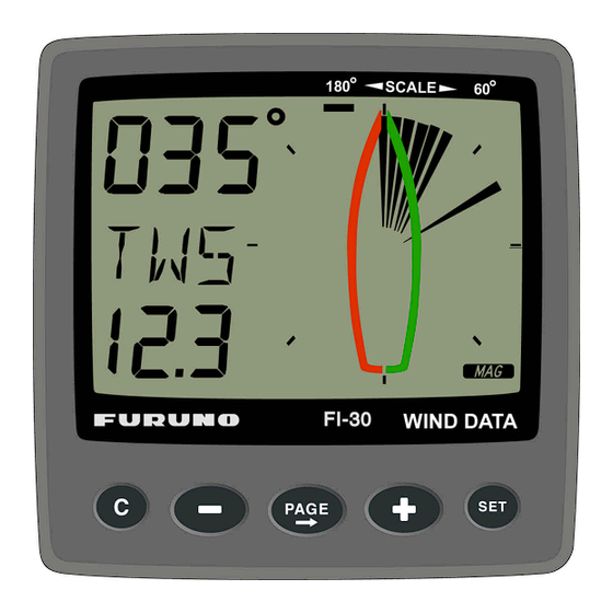
Main function Top data is relative Wind angle, [AWA] (Apparent Wind Angle). As an alternative to [AWA] the following can be displayed: [AWS] (Apparent Wind Speed). [TWA] (True Wind Angle) if the log transducer is connected. [TWS] (True Wind Speed) if the log transducer is connected. To change between these functions, see C12, 6.1.2. -
Page 19: Sub-Functions
Sub-functions Select sub-function with PLUS or MINUS. Information text for the sub-function is displayed. You may also ”park” your favourite function so it will automatically be displayed after power on. Press both PAGE and SET to ”park” the displayed function. The display will flash once to confirm that you have ”parked”... -
Page 20: Battery Voltage [Bat], Option
5.5.5 Battery voltage [BAT], option The text [BAT] will display battery voltage. The voltage is measured inside the instrument and will not compensate for any voltage drop caused by installation. 5.5.6 Boat speed [BSP], option The text [BSP] will display boat speed (water speed). The text [BSP] will toggle with selected unit, i.e. - Page 21 On the display you will see the text TRM and AWA toggling together with your Wind angle. On the graphic part you will see your reference angle as one straight horizontal segment when actual angle is equal to the pre-set angle. At the same time you will see apparent and true Wind angle.
-
Page 22: More Functions In A Nexus Network
Press SET to set [BSP] reference. The display will now show you the text [%] toggling with text [BSP] or whatever trim you have selected. The speed variation is expressed in % from set value. Press the SET every time you wish to set a new trim reference value. -
Page 23: Geographic Wind Direction (Twd)
”pointer”. If the Compass transducer is missing but there is a GPS installed, you may use the GPS as a reference for heading under the criteria that the vessel must be moving. Change C33 from USE Hdc to USE COG. -
Page 24: X-Track Error, Xte
5.6.3 X-track error, XTE To get this function, set NAV = On C14 (See 6.1.4). The text [XTE] is displayed shortly when this function is selected, then a symbolic ”boat” is displayed on one side of the ”road” which is displayed as three vertical lines. Your ”boat”... -
Page 25: Btw / Nxt, Bearing And Angle Deviation Relative Next Course
You may use COG but our recommendation is to use the Compass since the response and accuracy is superior. If you use COG without a differential GPS you will loose too much accuracy in the information. [BTW] and [NXT] is toggling. - Page 26 Down Wind: When sailing down Wind, the boat can always be sailing at the highest WCV (speed towards the mark). When [NXT] is [00 ] you should jibe because your drift is not important. The functions [BTW] and [NXT] is toggling, but can be locked or unlocked by use of the SET.
-
Page 27: Calibration
Calibration To get the most out of your FI-30 instrument, it is important to carefully calibrate the instrument. The calibration values are stored in a non volatile memory. To access calibration PAGE, press and hold SET more than 2 seconds. To select a calibration code, press MINUS, PLUS and PAGE as required. -
Page 28: C13 Displaying Boat Speed, Trip Log And Temperature, Option
6.1.3 C13 Displaying boat speed, trip log and temperature, option When set to OFF, the functions will be removed from the display. The Wind Data instrument may be used as a Server in the Nexus Network, transmitting the log and temp to other FI-30 instruments without having the information displayed in this instrument. -
Page 29: C23 Unit For Temperature
Select heading Compass [Hdc] when the Compass transducer is connected to the Nexus Network (recommended). Select course over ground [COG] when a GPS navigator is connected, but no Compass. Select STA for static use at fixed installations, such as at the yacht club, airfield, ferry berth and so on. -
Page 30: C50 Wind Settings
C50 Wind Settings To return to normal PAGE, press SET when the text [rET] is displayed. 6.4.1 C51 Network setting of true or apparent Wind angle Select true [TWA] or apparent Wind angle [AWA] as main function. The optional analogue Wind instrument will display the same selection. -
Page 31: C63 Speed Reference, Water Or Gps
BTW. When [SOG] is selected, the reference is speed over ground. Note! the boat must be moving to give correct readings. We also recommend you to use differential GPS to get good readings. 6.4.7 C64 Wind trim reference This default reference for Wind angle trim. -
Page 32: C70 Configure Fi-30
C70 Configure FI-30 To return to normal PAGE, press SET when the text [rET] is displayed. In the configuration you will be able to tell the Nexus Network where you have installed the log and Wind transducer. This is important because you may optionally install those transducers at the Server too. -
Page 33: Connection Of Trim Button
6.5.4 Connection of trim button Connect the trim button as per the drawing. button connection when pressed. It is also possible to connect more than one button in parallel, for example one on starboard and one on port. Article number for the push button: 19763. -
Page 34: Maintenance And Fault Finding
Fault finding Before you contact your FURUNO dealer, and to assist your dealer to give you a better service, please check the following points and make a list of: All connected instrument and transducers, including their software version numbers. -
Page 35: Fault - Action
OK. If the voltmeter shows 0 or 5 V DC at both measuring points, the transducer or the connections are defect. Contact you FURUNO dealer with this information. 2. Speed and distance functions: No reading [ --- ] C13 should be ON. -
Page 36: Specifications
Specifications Technical specifications Dimensions: Instrument cable: Power supply: Power consumption Instrument: Log- and temp sensor: Wind transducer: Temperature range: Weight: Enclosure: CE approval The products conforms to the EMC requirements for immunity and emission according to EN 50 08-1, Nexus Network introduction and user policy Introduction: The Nexus Network is a Multi talker Multi receiver data bus specially designed for marine navigation applications. -
Page 37: Equipment Lists
Equipment Lists INSTRUMENT SERIES PART # MODEL 000-041-864 FI-301 000-041-865 FI-301-SERVER 000-041-866 FI-301-SERVER/SENSOR MULTI CONTROL W/SERVER & SENSORS 000-041-867 FI-302 000-041-868 FI-302-SENSOR 000-041-869 FI-303 000-041-870 FI-303-SENSOR 000-041-871 FI-304 000-041-872 FI-305 000-041-873 FI-306 000-041-874 FI-307 000-041-875 FI-308 000-041-876 FI-309 000-041-877 FI-310... -
Page 38: 10 Abbreviations
10 Abbreviations Boat Speed Bearing To Waypoint Celsius Fahrenheit KiloMetre KnoTS Miles per Hour Liquid Crystal Display RETurn Speed Over Ground TRiP Minus Plus...
Need help?
Do you have a question about the FI-303 and is the answer not in the manual?
Questions and answers