Table of Contents
Advertisement
Advertisement
Table of Contents
Troubleshooting

Related Manuals for AMT Datasouth Accel-7350


Summary of Contents for AMT Datasouth Accel-7350
-
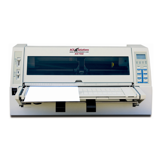
Page 1: Service Manual
Accel-7350 Dot Matrix Printer Service Manual Document #130034... - Page 2 This Manual is to help qualified service engineers repair or adjust your AMT ACCEL- 7350 Printer. Please read the manual carefully before repairing and adjusting your AMT ACCEL-7350 Printer. The warranty will not cover any trouble with or damage to the printer resulting from repair or modification by unqualified persons.
-
Page 3: Table Of Contents
TABLE OF CONTENTS Printer Specifications Parallel Interface Specifications Serial Interface Specifications Print Head Adjust Label Printer Features Hexadecimal Dump Function Self Test Function Safety Auto Stop Function Print Head Gap Adjustment Print Position Adjustment Paper Feed Position Adjustment Wiring Diagram Control Diagram Troubleshooting Control ROM and PCB Replacement... - Page 4 TABLE OF CONTENTS Replacement of Sensors Parallelism Adjustment Lubrication Electronic Repairs HA Motor Driver Circuitry Ribbon Motor Driver Circuitry MC Motor Driver Circuitry LF/HC Motor Driver Circuitry Print Pin Driver Circuitry Detecting Circuitry Power Supply PCB Indicator Circuit I/F Circuit Slide SW Circuit Power Circuit Exploded Drawings and Part Numbers...
-
Page 5: Printer Specifications
1. GENERAL PRINTER SPECIFICATION 1.1. Description 24 pin Serial Dot Matrix Printer Flat bed, Wide Carriage Beige Color 1.2. Dimensions: At Operation - (W) 25” [635 mm] x (D) 18.3” [465 mm] x (H) 11.6” [294mm] At Storage (without paper tractor and paper support) – (W) 25”... -
Page 6: Media Parameters
2.9. Ribbon Type - Cassette with endless fabric ribbon Ribbon Life -15 million characters in draft mode Color - Real Black 2.10. Paper Handling Fanfold Paper, Front Push Insertion: Front Ejection: Rear Paper Width: 8 ~15” (203.2 mm–381 mm) Fanfold paper, Rear Push Insertion: Rear Ejection:... - Page 7 Fanfold (Multi-parts) Paper Width: 8 ~15” (203.2 mm–381 mm) Paper Thickness: .005~.02” (0.12 mm–0.52 mm) Number of Copies: Original + 7 max Unprintable Area: Top: .012” (3 mm) Bottom: .012” (3 mm) Before Perforation: .012” (3 mm) After Perforation: .012” (3 mm) Fanfold (Label) Paper Width: 8 ~15”...
- Page 8 Card with Manual Insertion Paper Width: 7.2~16.9” (182 mm–430 mm) Paper Length: 7.2~16.9” (182 mm–430 mm) Paper Thickness: .003~.079” (0.08 mm–2.0 mm) Paper Weight: 16~47 lbs Paper Type: Plain Paper Unprintable Area: Top: .012” (3 mm) Bottom: .012” (3 mm) Right: .012”...
- Page 9 4.6. Barcode Symbology Industrial 2 of 5 Interleaved 2 of 5 Matrix 2 of 5 Codabar Code 11 Code 39 Code 93 Code 128 EAN-8 EAN-13 UPC-A UPC-E Postnet Element (created in elements) 4.7. Graphics Resolutions 360 x 180 dpi (HXV), Horizontal adjacent dots cannot be printed 4.8.
- Page 10 7. DETECTION & PROTECTION FUNCTION 7.1. Type Paper Detection Paper Jam Detection Paper Skew Error Detection Head Overheat Protection Cover Open Detection ACOUSTIC NOISE 8.1. Specification Less than 58 dB(A) (LQ printing, fanfold, ISO 7779) RELIABILITY & SAFETY 9.1. Print Head Life 300 million stroke / pin 9.2.
- Page 11 10. POWER 10.1. Power Supply AC 220V -10%, AC 240V +10%, Frequency 50 Hz/60Hz AC 100V -10%, AC 120V +10%, Frequency 50 Hz/60Hz 10.2. Power Consumption LQ Self Printing: 140W Draft Self Printing: 170W Stand-by: 40W Energy Star mode: 15W 11.
-
Page 12: Parallel Interface Specifications
Parallel Interface Specifications Cable Side Connector DDK 36-pin 57-30360-D8 or equivalent Printer Side Connector ELCO 36-pin 00834-6360020858 or equivalent Cable type Twisted paired cable with ground line and maximum of 10 feet. SIGNAL IN/OUT SIGNAL IN / OUT STROBE* DATA 1 DATA 2 DATA 3 DATA 4... - Page 13 Printer Input Signals DATA1-DATA8 8bit data signals with DATA 1 being the Least Significant Bit (LSB), and DATA 8 being the Most Significant (MSB). STROBE* A strobe signal for reading 8-bit data. When this signal goes "low", data is read. The data is latched on the falling edge of STROBE*.
-
Page 14: Serial Interface Specifications
Printer Output Signal Levels All the signals used in the printer are in the TTL levels. "HIGH" level: +2.4 to 5.0 [V], "LOW" level: 0 to 0.4[V] Measured at input terminals of the printer. Serial Interface Specifications Cable Side Connector 25-pin (male type) Printer Side Connector 25-pin (D-sub connector (female type) - Page 15 Printer Input Signals Receive Data A serial data line that consists of a start bit, data bits, (party bit), and stop bit. The configuration of the data length (7 or 8 bits), parity and stop bit are set in the setup mode from the control panel.
- Page 16 XON/XOFF Protocol A protocol whereby the printer sends to the host XON (11h) and XOFF (13h) codes to indicate the printer the printer's state. The XOFF (13h) code is sent to the host to indicate not ready. In either the busy or offline state, CTS is held "low".
-
Page 17: Print Head Adjust Label
Print Head (HA) Adjust Label The numbers shown in the table on the HEAD ADJUST label represent the settings made prior to shipment. These settings will be erased from the EEPROM by initialization routine 3. After initialization routine 3 is performed, restore the settings shown on the label (settings made prior to shipment). -
Page 18: Printer Features
(4) MULT (HA MULTIPART ADJUST) The HA MULTIPART ADJUST sets the print density for copy paper. The HA MULTIPART ADJUST setting adjustment is enabled only in the HA auto mode. The HA MULTIPART ADJUST setting is adjustable between -5 and +10. As the setting decreases, the print darkness increases. -
Page 19: Hexadecimal Dump Function
Hexadecimal Dump Function The hexadecimal dump function produces an exact printout of the codes received by the printer. To enter the hexadecimal dump mode, depress the SPEED key while turning on the printer's power. Continue pressing key until the display reads “Hex Dump”. Draft mode Hexadecimal Dump: Power ON + SPEED key LQ mode Hexadecimal Dump: Power ON + SPEED key + ONLINE key When the host sends output to the printer, all codes and data are printed in hexadecimal format. -
Page 20: Safety Auto Stop Function
Safety Auto Stop Functions • Cover Open Sensor When the front cover is open: The printer stops printing (C motor is disabled, but front operation keys -LF, RLF, MICRO LF, MICRO RLF - are operable). "FRONT COVER OPEN" is displayed on LCD. The ONLINE lamp blinks. -
Page 21: Print Position Adjustment
(6) Based on the gap adjustment pattern printout, select the gap adjustment settings that will provide the optimum print density. Designate the selected gap adjustment setting on the LCD using the [↓] and [↑] keys. Press the [ENTER] key and the printer will adjust the head gap using the selected settings and print out the confirmation pattern. - Page 22 The timing pattern printout shows six speed modes from Mode 1 to Mode 6 in Mode A and seven Speed modes from Mode 0 to Mode 6 in Mode B, and 13 timing numbers will be printed for each Speed mode. The LCD display is as shown below.
-
Page 23: Paper Feed Position Adjustment
Paper Feed Position Adjustment This printer detects the edge of the loaded paper with the edge sensor (reflection type) on the ribbon guide of the print head and feeds the paper to the TOF position. If the feed position of a printer is judged to be out of position by more than the specified distance, due to variance between individual printers, it is adjusted before shipment. -
Page 24: Wiring Diagram
Wiring Diagram... -
Page 25: Control Diagram
Control Diagram... -
Page 26: Troubleshooting
Troubleshooting Control ROM and PCB Replacement When an EEPROM error or sensor problem arises, if there is no mechanical problem and if the control ROM on the PCB is not the latest version, then replace the control ROM with the latest version. -
Page 27: Troubleshooting Guide
Troubleshooting Guide Appearance Checks Localize defective parts such as broken switches and levers, damaged FFC cable, loose connections, burned components or blown fuses. Functional checks Define the defective functional block without disassembling the printer: • Power-on initialization check (Checking printer power) •... -
Page 28: Error Message Remedies
Error messages & Remedies HEAD PROTECTION • Print head is overheated. The printer automatically resumes to its normal print operation when the print head cools down. FRONT COVER OPEN • Front Cover is opened. Check if the cover is closed properly. Check the cover open sensor connector (CN25) on Main PCB. - Page 29 • The Head Adjust (hereinafter HA) Sensor detects an error when the HAI SENSOR ERROR head is moved to the home position for HA. Check to determine whether anything is obstructing the operation of the HA Motor. Check the connection of the HA Sensor harness. If it is connected properly, replace the HA Sensor or the Main PCB.
- Page 30 • The MC Sensor (Front Tractor) detects an error when the printer is FUNCTION MCMTR3 ERROR initialized or when the paper feed path is changed. Check to determine whether anything is obstructing the operation of the Front Tractor Motor. Check the connection of the MC Sensor (Front Tractor) harness. If it is connected properly, replace the MC Sensor (Front Tractor) or the Main PCB.
- Page 31 • PAPER EDGE SENSOR The difference between the maximum and minimum Paper ERROR Sensor values falls below the specified level during the sensor instruction operation. Check to determine whether paper is loaded into the printer during the sensor instruction operation. (This error also occurs if paper is not loaded properly due to a paper jam.) Check the connection of the Paper Sensor harness.
-
Page 32: Trouble Symptoms
Trouble Symptoms The lamp does not light and no display on LCD Possible cause: Power cable is defective or loose. Power lines from the power switch are disconnected. Loose connection between the main PCB and indicator PCB. Loose connection on the Main PCB and power PCB. Fuse (F1) is blown. Power PCB circuitry is defective. -
Page 33: Abnormal Printing
Abnormal printing Dot is missing in horizontal direction. Possible cause: A pin in the printhead is defective. Main PCB is defective. Remedy: Replace the print head if a print pin is bent or broken and if 14 Ω of resistance between GND and each pin is not measured on the print head terminal. -
Page 34: Repair Flow Charts
Repair Flow Charts The following are only for troubleshooting to a functional block level. Problems Jammed Ribbon Jammed or dragging ribbon Is the printhead printing with good quality? - Page 35 Dots Missing Caution: Do not touch the print head immediately after printing because it may be too hot.
- Page 36 Extra Dot Printing (Improper character)
- Page 37 Incorrect Printing (Irregular print data)
- Page 38 No LCD Display (Half of the LCD lights up)
- Page 39 No LCD Display (Completely blank)
- Page 40 Control Keys Not Functioning...
- Page 41 No Buzzer Abnormal Ribbon Feeding (Causing abnormal carriage movement)
- Page 42 No Line Feed or Inconsistent Line Feeding...
- Page 43 Carriage Error...
- Page 45 "HEAD PROTECTION" displayed but nothing happens Caution: Do not touch the print head immediately after printing because it may be too hot.
- Page 46 Cover Open Error Will Not Cancel With Cover Closed...
- Page 47 No Fanfold Paper Reverse Line Feed...
- Page 48 Printing Does Not Stop After Paper Is Ejected...
- Page 49 Not Powering Up...
-
Page 50: Mechanical Replacement
Mechanical Replacement Enclosures (1) Top Enclosure and Printer Cover Replacement REMOVAL Step 1. Remove 3 pan head screws (S-16) on the front and 4 truss head screws (S-22) on the back to remove the top enclosure. (2) Paper Rack Assembly Replacement REMOVAL Holding the external edge of the paper rack with your hands, raise the front edge up to a vertical position, and then lift up the paper rack gently. - Page 51 (3) Mechanical Block Replacement REMOVAL Step 1.The paper rack and cover L/R must be removed. Step 2. The top enclosure must be removed. Step 3. Remove 1-pan head screws (M4 x 32.6) on the right front mechanism holder B, rotate the metal plate to the right.
-
Page 52: Print Head And Ffc Cable Replacement
Print Head and FFC Cable Replacement REMOVAL (Print Head) Step 1. Open the printer front cover and remove the ribbon cassette. Step 2. Remove 2 pan head screws (S-6) that are securing the print head onto the carrier. Remove 1 screw from the carrier cover and pull the printhead toward the front of the printer. -
Page 53: Ribbon Guide Assembly Replacement
Ribbon Guide Assembly Replacement TOOLS: Philips Screwdriver, six inch long .002” (qty-1), and .004” (qty-2) Feeler Gauges REMOVAL Step 1. Remove the printer top cover, 7-pan head screws. Step 2. Remove ribbon cassette. Step 3. Remove the carrier cover, 1-pan head screw. Step 4. -
Page 54: Carriage Motor Assembly Replacement
Carriage (C) Motor Assembly Replacement TOOL: Screwdriver REMOVAL Step 1. The top enclosure must be removed. Step 2. Remove 2 pan head screws (S-17) from the mechanism stoppers left and right corners of the printer chassis. Step 3. Lift up the back of the mechanism and disconnect the C motor harness from the connector on the control PCB unit. -
Page 55: Carriage Timing Belt Replacement
Carriage Timing belt replacement REMOVAL Step 1: Remove 4 captive screws securing the C motor to the motor plate, and then remove the timing belt from the motor pulley. Step 2: Remove the timing belt from the idler pulley assembly by simply dislocating the idler pulley assembly from its holder. -
Page 56: Line Feed Motor Assembly Replacement
Line Feed (LF) Motor Assembly Replacement REMOVAL Step 1. Remove the top enclosure. Step 2. Remove 2 pan head screws (S-17) from the mechanism stoppers left and right corners of the mechanism. Rotate the mechanism up. Step 3. Disconnect the LF motor harness from its connector in the control PCB unit. Step 4. -
Page 57: Platen Replacement
Platen Replacement REMOVAL Caution: avoid getting grease on the platen. Step 1. Remove top enclosure. Step 2. Remove 2 pan head screws (S-17) from the mechanism stoppers left and right corners of the printer chassis. Rotate the mechanism up. Step 3. Detach the plastic gear on the left side of the platen shaft by removing1 pan head screw (S-16). - Page 58 Step 4. Slide the carrier to extreme left along the F guide shaft. Step 5. Slide the pinch roller drive shaft to the left and then right out of the mechanism. INSTALLATION FC Shaft Follow the reverse of the above procedure. Note: When installing the pinch roller shaft assembly, the "D"...
-
Page 59: Ribbon Motor Assembly Replacement
Ribbon Motor Assembly Replacement REMOVAL Step 1. Remove the top enclosure. Step 2. Remove 2 pan head screws (S-17) from the mechanism stoppers left and right corners of the mechanism. Rotate the mechanism up. Step 3. Remove 2 pan head tapping screws (S-11) from the ribbon motor assembly. Note: Replace motor with cable connector located on right lower side. -
Page 60: Ha Motor Replacement
HA Motor Replacement REMOVAL Step 1. Remove the top enclosure. Step 2. Remove control panel support bracket 2 pan head screws. Step 3. Remove HA sensor-fixing plate, 1 pan head screw (S-4). Step 4. Remove 4 pan head tapping screws (S-11) to disassemble the HA motor Fixing Plate. Step 5. -
Page 61: Paper Edge Sensor Replacement
Paper edge sensor replacement REMOVAL Step1: Turn off the printer power switch, and then open the printer cover, move the print head to the left of the printer. Step2: Remove ribbon cassette. Step4: Remove the carrier cover. Step5: Remove the paper edge sensor cover. Step6: Remove the paper edge sensor(s). -
Page 62: Carriage Replacement
Carrier replacement REMOVAL Step1: Remove the F guide shaft support “E” rings (left and right), remove both support brackets, and the springs. Step2: Remove the F guide shaft screw, Adjust shaft and two bearings. Step3: Remove the two HA motor screws from the fixing plate. Step4: Remove the screws on the HA cam L/R (left and right side of the mechanism). - Page 63 Step5: Remove the “E” rings from inside of the F guide shaft, remove the bearings. Step6: Remove carrier cover screws, and cover. Step7: Remove the two print head screws and detach the print head FFC- A, B and C cables. Step8: Remove the 4 captive screws that are holding the C motor to the fixing plate, then remove the timing belt from the C motor pulley.
-
Page 64: Replacement Of Sensors
Step10: Remove the carrier assembly to the left of the printer. Step11: Remove F guide shaft from the base plate R. INSTALLATION Follow the reverse of the above procedure Replacement of Sensors (1) FC Home Sensor Assembly Replacement FC Home Sensor Assembly consists of one FC home, and one OP home sensor located on base plate L assembly. - Page 65 (2) FC Home Sensor B Assembly Replacement FC Home Sensor B Assembly consists of one FC home, and one OP home sensor located on base plate R assembly. REMOVAL Step 1. Remove the top enclosure. Step 2. Remove 2 pan head screws (S-17) from the mechanism stoppers left and right corners of the mechanism.
- Page 66 (3) Home Sensor Assembly Replacement Home Sensor Assembly is located on the left side of the FFC bottom plate assembly. REMOVAL Step 1. Remove the top enclosure. Step 2. Remove 2 pan head screws (S-17) from the mechanism stoppers left and right corners of the mechanism.
- Page 67 (5) Paper Edge Sensor Replacement The Paper Edge Sensor is located on the ribbon guide assembly. REMOVAL Step 1. Remove the carrier cover, 1 pan head screw (S-6). Step 2. Disconnect the harnesses of the paper edge sensor from the head connecting PWB. Step 3.
-
Page 68: Parallelism Adjustment
Parallelism Adjustment F Guide Shaft Parallelism Adjustment Parallelism is required when print darkness differs between the right and left sides of the paper. The following adjustment is intended for minor adjustment only. Contact the manufacturer for major adjustments. PROCEDURE: Step 1: Remove the Top Enclosure. Step 2: Loosen the F Guide Shaft Adjust screw on the right end of the F Guide Shaft. -
Page 69: Lubrication
Lubrication The manufacture specified lubricants should be used. Their usage and applicable areas are specified in the Exploded View. Part Numbers Description EM60L Apply between plastic parts, such as gears and pinch roller holder. Apply between the metal and plastic parts such as a gear and lever SFP-6 axle (metal stud). - Page 70 Lubrication Examples ? ? ? ? ? ? EM60L, between mating gears. SFP-6, between the metal and plastic parts. HV-22, applied to carriage felt washers and main shaft.
-
Page 71: Electronic Repairs
Electronic Repairs Introduction This section will limit the explanation to the operational principles of the circuitry. The Cable Connection table below shows the interface of the electronic assembly with the mechanical assembly. You may be able to check the possibility of the connection faults or the mechanical defects at this point. - Page 72 Port Explanation (1) X0,X1(Input): Terminal for oscillator (25 MHz) (2) XRESET(Input): Reset signal input. (3) A0-A22(Output): Address bus. (4) D0-D7(I/O): Data bus. (5) XRD, XWR(Output): Read signal, write signal. (6) A19/A18, A17/A16(Output): Address for DRAM. (7) XRAS, XCAS(Output): Signal for DRAM control. (8) SYSCLK (Output):12.5 MHz (Original oscillation frequency of 25 MHz is divided into 2).
- Page 73 ● MB90705H pin assignment EEPROM CAT93C56J EEPROM of serial I/O of SOP, 8 pin, 2k bits. Main Function Maintains printer setup data (information including number of print lines, margins, starting position for printing and lateral alignment). Data is read when power is turned on, and data is written at setup and when power is turned off.
- Page 74 Terminals Explanation: D0 (Output): Data output. Connect with PB3 of CPU. D1 (Input): Data input. Connect with PB1 of CPU. CS (Input): Chip select. Active when "High". Connect with PB2 of CPU. CLK (Input): Clock for write/access data. Connect with PB0 of CPU. Gate array BBG010 QFP, 120 pin.
- Page 75 Port Explanation (1) AL0-AL5(Input): Address input. (2) AM8-AM15(3 state): Output address to DRAM for DMA. (3) DRA8, DRA9(3 state) Output address to DRAM for DMA. (4) AH18-AH22(Input) Address input. (5) D0-D7(I/O): Data bus. (6) XRD, XWR(Input): Read signal, write signal. (7) XRAS, XCAS(3 state): Control access to DRAM of DMA.
- Page 76 ● BBG020 pin assignment Port Explanation (1) A0-A5 (Input): Address bus. (2) D0-D7 (I/O): Data bus. (3) XCSIN (Input): Chip select. (4) XRD, XWR (Input): Read signal, write signal. (5) IREQ1 (Output): This signal turns to "High" at sensor interrupt. Refer to CPU INT3 item. (6) DS1, 4, 5(Input): Sensor input.
- Page 77 Main Function Controls centronics I/F Controls serial I/F Port Explanation (1) A0-A5(Input): Address bus. (2) D0-D7(I/O): Data bus. (3) XCSIN(Input): Chip select. (4) XRD, XWR(Input): Read signal, write signal. (5) INTREQ(Output): "High" for centronics I/F initial input. (6) DTXREQ(Output): "High" for centronics I/F data input. (7) SYNC0(Input): 12.5 MHz clock.
- Page 78 ● BBG030 pin assignment Regarding DMA BBG010 transfers printing data to BBG010 directly by DMA from DRAM without going through the CPU in order to transmit data developed in DRAM to BBG010 from DRAM at high speed (DMA: Direct Memory Access). The following is an explanation of this process. 1.
-
Page 79: Ha Motor Driver Circuitry
HA Motor Driver Circuitry The HA motor is a 4-phase stepper motor, driven by double-phase, and controlled by BBG020. During standby, transistor Q7 is turned OFF and the HA motor is supplied with standby current from the 40 V power line through R209. This standby current is necessary to stop the HA motor smoothly. -
Page 80: Ribbon Motor Driver Circuitry
Ribbon Motor Driver Circuitry The ribbon motor is a 4-phase stepper motor, driven by double-phase, and controlled by BBG020. During standby, transistor Q5 is turned OFF and Q6 is turned ON so that the ribbon motor is supplied with standby current from the 40 V power line through R205 and R207. This standby current is necessary to stop the ribbon motor smoothly. -
Page 81: Mc Motor Driver Circuitry
MC Motor Driver Circuitry The MC motors are 4-phase stepper motors, driven by double-phase, and controlled by BBG020. There are four MC motors: MC1 to MC4. To select a motor to operate, set the motor’s corresponding signal of MCON1 through MCON4 to HIGH. Only one motor may be operated at a single time;... -
Page 82: Lf/Hc Motor Driver Circuitry
LF/HC Motor Driver Circuitry The line feed (LF) motor and head carriage (C) motor are both a 4-phase stepper motor, driven by 1/2 phase (C motor) or 2-phase (LF Motor), and controlled by U24 (BBG020) and U1(CPU). The signals (LF motor: LFA, LFB, XLFA, XLFB, LFBA, LFBB, LFBXA, LFBXB and C motor. HCA, HCB, XHCA, XHCB) are phase drive signals, which controls the direction and the step width of the motor. - Page 83 C motor drive circuit C motor uses a 4-phase stepper, and it is set in single phase by BBG020 at standby 1/2- phase at rotation of the motor. The current value reaching the motor is decided by turning on HCDR0–HCDR4. Drive Method Data control signals from the gate array consist of a speed control and phase signals.
- Page 84 Drive method Data control signals from gate array consist of speed control and phase signals. The speed control signal is set at a certain voltage level by transistors QA10, QA11 and resistor R167, R172 and R179, and is supplied to U22. This voltage level determines how U22 controls the current, which flows to the motor.
- Page 85 Drive method Data control signals from gate array consist of speed control and phase signals. The speed control signal is set at a certain voltage level by transistors QA11, QA12 and resistor R180, R182 and R183, and is supplied to U23. This voltage level determines how U23 controls the current, which flows to the motor.
-
Page 86: Print Pin Driver Circuitry
Print Pin Driver Circuitry The control signal from Gate Array turns on or off the transistors SMA5106 (QA1-QA6). When the transistor is turned ON, the current starts flowing out of the print pin coil and producing the pin striking force due to a electromagnetic phenomenon. When the transistor is turned OFF, the current persists to flow due to the existing electromagnetic field and creates negative high voltage at point A. - Page 87 Printhead Pin Configuration The print head has 32 pin terminals. Approximately 14.7 ohms of resistance should be measured between COMMON terminal and each pin terminal. C: Common T1, T2:Thermistor When high temperature is detected in the print head, the printer automatically takes the following actions: Temperature >...
-
Page 88: Detecting Circuitry
Detecting Circuitry MC sensor (Rear tractor) When the rear tractor is selected, the micro switch turns ON, causing No. 12 of U20 to set to LOW. Note: MC Sensor (Front tractor), Tractor Paper Sensor (Rear/Front) belong to this circuit type. Refer to the circuit diagram for those details. - Page 89 Power cutoff detection When the power of the CPU is cutoff or 40 V system power voltage falls below 30 V due to trouble, PWOFF signal turns to "1" and the CPU is interrupted. When the CPU accepts this interrupt, it finishes all printing and mechanical action and writes necessary data (present paper position) to EEPROM.
- Page 90 Home Sensor A photo-interrupter type sensor is used to detect a carrier position. If the voltage level at HS (U24/ 70) is LOW, the printer detects the carrier at home position. If the carrier is out of the home position, the voltage level is HIGH. Note: Circuit type: Head Adjust Sensor, Cover Open Sensor and Mc Sensor (front/rear friction)
-
Page 91: Power Supply Pcb
Power Supply PCB Outline This is a self-oscillating, RCC type switching power supply circuit. The output voltage is controlled by the switching frequency. The rated input is 120V, 60Hz for U.S.A. and 100V for JAPAN setting (adding to the Jumper at CN2) and 230V, 50Hz for European setting (Removing the Jumper at CN2). -
Page 92: Troubleshooting Flow
Troubleshooting flow Power Supply PCB Troubleshooting flow. When the power switch is turned on. Is AC power cord properly attached? • Turn the power switch off then reinstall the power cord again. Fuse blown? • Check the jumper of CN2 (for 100V/120V model). •... - Page 93 (First, check 40V-generating circuit, because +5V is regulated from the 40V output.) If using a “X100” attenuator built-in probe, check the waveform at 200KHz frequency between the drain of P1 and primary GND (heat sink panel of P1). Else check all following possibilities. P1 OK? •...
-
Page 94: Indicator Circuit
Indicator Circuit... -
Page 95: I/F Circuit
I/F Circuit... -
Page 96: Slide Sw Circuit
Slide SW Circuit... -
Page 97: Power Circuit
Power Circuit... -
Page 98: Exploded Drawings And Part Numbers
Exploded View (1/6) Following pages require Legal size paper for printing. - Page 99 Exploded View (2/6)
- Page 100 Exploded View (3/6)
- Page 101 Exploded View (4/6)
- Page 102 Exploded View (5/6)
- Page 103 Exploded View (6/6)
- Page 104 Assemblies Reference Part Parts Name Number Number N104-4000 1~177 Mechanism N104-205U 130407 1~178 Paper Rack N104-6040A 1~179 Tractor Unit 95150-239A 130414 1~162 Indicator House Assembly N104-263A 130403 1~172 I/F PCB Assembly 95150-093A 130413 1~164 Slide SW Cover Assembly 95150 1~168 External Electric 95150-5001A 130404...
- Page 105 N104-067A 1~180 FC Home Sensor Assy N104-067BA 1~181 FC Home Sensor B Assy N104-068 4860 FC Home Sensor Fixing Plate N104-069 4812 Friction Spring 2 N104-070 4887 FC Reduction Gear C N104-071 4888 FC Intermediate Gear B N104-072 4890 FC Cam BR N104-073 4868 FC Cam BL...
- Page 106 N104-156B 130438 4867 Rear Guide Roller Spacer N104-157 4923 Carrier Sprint N104-158A 130409 1~186 Home Sensor Assembly N104-159 4927 Home Sensor Cutoff Plate N104-160A 130401 1~187 Ribbon Guide Assembly N104-160 4653 Ribbon Guide N104-162 130463 4654 Ribbon Mask N104-161 130434 4679 Carrier Stopper N104-163A...
-
Page 107: Tractor Assembly
Paper Rack PART NO.: N104-205U SAP: 100000000178 Reference Part Parts Name QTY/ Number Number Assy N104-193 5376 RU Removable Lever N104-199U 130415 1~193 Rack Cover R Unit N104-190BA 4537 RU Holding Plate R Assembly N104-191 4558 RU Support Plate N104-192BA 4549 Tractor Support Plate R Assembly... - Page 108 Indicator House Assembly PART NO.:95150-239A SAP: 100000000162 Reference Part Parts Name Specification/Model Location Number Number N104P-252 4726 Indicator Plate N104P-239 4731 Indicator House N104P-238 4744 LCD Cover N104P-4722 4722 Screw P.H.T. Screw(BT)3*12 N104P-127 4747 Indicator Stand N104P-4749 4749 Screw P.H.T. Screw M2*10 N104P-1953 1953 Hexagon Nut M2...
-
Page 109: Main Pcb Assembly
Slide SW Cover Assembly PART NO.:95150-093A SAP: 100000000164 Reference Part Parts Name Specification Location Number Number /Model N104P-183 4815 Slide SW Fixing Plate N104P-93 4817 Slide SW Cover N104P-253 4819 Knob N104P-92 4821 Click Seal N104P-4722 4722 P.H.T. Screw(BT)3*12 N104-264A 1~176 Volume PCB Ass’y N104P-4826... - Page 110 84091-0654 SLA7026M U19,U22,U23 Ceramic N104P-4534 4534 25.00M Pitch: .2” Oscillator 84090-7408 3917 Transistor Array SMA5106(4A 100V) QA1-QA6 QA15- 84090-7407 4543 Transistor Array MP4021(100V 2A) QA18,QA20, QA21 FMG8A-T148(100mA 84090-7431 4546 Transistor 50V) QA7-QA12 Dual NPN QA13,QA14,QA FMG9A-T148(50mA 50V) 84090-7432 4548 Transistor Dual NPN QA22,QA23 FMG11A-T148(100mA...
- Page 111 R155,R156,R17 N104P-3397 3397 Chip Res. 47kohm(+/-5% 1/10W) R174,R189,R19 R39,R40,R48,R R55,R248,RA25 N104P-4587 4587 Chip Res. 0ohm(+/-5% 1/10W) RA60,RB51,RB RB54,R41,R58, R70,J15-J22 R154,R167,R18 N104P-4590 4590 Chip Res. 22ohm(+/-5% 1/10W) N104P-4596 4596 Chip Res. 30ohm(+/-5% 1/10W) R195,R181 N104P-4490 4490 Chip Res. 68ohm(+/-5% 1/10W) R163 N104P-4599 4599 Chip Res.
- Page 112 Metal Oxide N104P-4641 4641 1kohm(3W +/-5%) R209 Res. N104P-5537 5537 Cement Res. 50mohm(3W +/-5%) R212 RA158,RB158,R A175, N104P-4642 4642 Cement Res. 0.33ohm(3W +/-5%) 2Pin RB175,RA191,R B191 Chip Ceramic N104P-4647 4647 5pF,50V,+/-5%,CH C13,C14 C117- Chip Ceramic N104P-4006 4006 100pF,50V 133,C147,C139, C140,CB3 C59,C60,C79,C Chip Ceramic N104P-4651...
- Page 113 N104P-4706 4706 Connector B5P-VH CN13 CN21,CN23,CN 84092-2702 4708 Connector B4B-EH 84092-1410 Connector B2P3-VH CN28 N104P-4711 4711 Fuse ICP-S1.0(1.0A 50V) F1-F24 N104P-4713 4713 Heat Sink 1.7” * 1.4” * .4” U19,U22,U23 N104P-450 Pan Head Screw M3*8 (U19,U22,U23) N104P-4716 4716 IC Socket 42 Pin N104P-5493 5493...
- Page 114 C12,C1 Pitch: 0.2 N104P-4401 4401 Ceramic. Cap 0.1uF,50V C19,C2 inch Pitch: 0.1 C15,C2 N104P-4403 4403 Ceramic. Cap 0.01uF,50V inch Metal Film 0.47uF,257V, 84090-2060 3848 RE474-C3.5 C1,2 Cap. UL/CSA/VDE,X2 Metal Film Pitch: 0.4 N104P-4409 4409 0.022uF,630V,+/-10% Cap. inch ECQB1H10 N104P-4412 4412 Film Cap.
- Page 115 Enclosure Material Reference Part Parts Name QTY/ Number Number Assy N104-210 4447 Top Enclosure N104-211A 1~196 Bottom Enclosure Ass'y N104-113 4477 Mech Stopper Support Plate N104-211 4469 Bottom Enclosure N104-219 4471 Rubber N104-227 4475 Mechanism Holder B N104-249 4472 Sound-absorbing Sheet N104-212A 130405 1~197...
- Page 116 Screws Reference Part Exploded Parts Name Location Number Number View No. N104P-450 S-24 Pan Head Screw Mechanism Holder B M3x8,SPW Paper Feed Shaft Gear (2) Paper Feed Shaft Intermediate Gear (2) FC Cam R (1) FC Cam BL (1) Pan Head Screw N104P-451 Indicator PCB (2) M3x10,SPW...
- Page 117 Pinch Roller Bearing(8) FC Shaft Guide (4) Cam Shaft (2) OP Gear (2) OP Reduction Gear (2) Reduction Gear B (2) Intermediate Gear C (2) FC Reduction Gear C (1) FC Intermediate Gear (1) Plate Intermediate Gear (1) Plate Reduction Gear (1) N104P-4730 130460 4730 Ring JE-4...
- Page 118 Plug Fixing Plate locating at Base Plate R(2) Ribbon Motor locating at Base Plate R/L(8) FC Home Sensor Fixing Plate(1) FC Home Sensor B Fixing Plate (1) Plug Fixing Plate locating at Paper Guide (2) Paper Guide B (4) Paper Guide C (4) Paper Cutter (2) Pan Head Tapping Screw Ribbon Motor on FFC Bottom...
Need help?
Do you have a question about the Accel-7350 and is the answer not in the manual?
Questions and answers