Table of Contents
Advertisement
Quick Links
Advertisement
Table of Contents

Related Manuals for GigE VA GigE Series

Summary of Contents for GigE VA GigE Series
- Page 1 User Manual English...
- Page 2 VA GigE series Revision History Version Date Description 2013-01-14 Draft 2 of 94 RA14-131-003...
-
Page 3: Table Of Contents
VA GigE series Contents Precautions ........................6 Warranty ..........................6 Compliance & Certifications .................... 7 FCC Compliance ......................7 CE : DoC ......................... 7 KC ........................... 7 Package Components ...................... 8 Product Specifications ..................... 9 Model ..........................9 Specifications ........................ 10 Camera Block Diagram .................... - Page 4 VA GigE series Setting the Exposure Time ..................... 35 Overlapping Exposure with Sensor Readout ..............36 Real Exposure ....................... 39 8.6.1 Timed Exposure Mode ........................39 8.6.2 Trigger Width Exposure Mode ......................40 Acquisition Timing Chart ....................42 Maximum Allowed Frame Rate ..................44 8.8.1...
- Page 5 VA GigE series 9.23 User Set Control ......................83 9.24 Field Upgrade ........................ 83 Appendix A Defective Pixel Map Download ..............84 Appendix B LUT Download ..................... 86 Luminance LUT ......................86 B.1.1 Gamma Graph Download ....................... 86 B.1.2 CSV File Download ........................88 Appendix C Field Upgrade ....................
-
Page 6: Precautions
VA GigE series 1 Precautions General Do not drop, damage, disassemble, repair or alter the device. Do not let children touch the device without supervision. Do not use the device for any other purpose than specified. ... -
Page 7: Compliance & Certifications
VA GigE series 3 Compliance & Certifications FCC Compliance This equipment has been tested and found to comply with the limits for a Class A digital device, pursuant to part 15 of the FCC Rules. These limits are designed to provide reasonable protection against harmful interference when the equipment is operated in a commercial environment. -
Page 8: Package Components
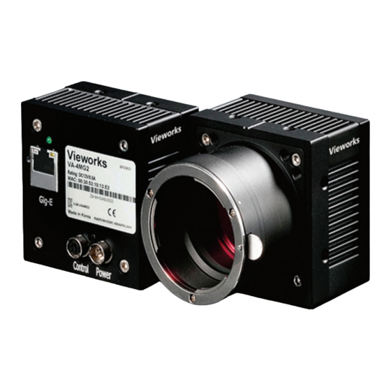
VA GigE series 4 Package Components Package Components VA Camera with C mount VA Camera with F mount Mount Plate (Optional) * VA-29MG2 will be offered with a cooling fan. It is also available without the fan upon request. 8 of 94... -
Page 9: Product Specifications
All features of VA GigE series can be programmed and easily updated in the field through Gigabit Ethernet interface. The camera is developed based on GenICam standard. The image processing and controls of VA GigE series are based on embedded FPGA with a 32 bit microprocessor. -
Page 10: Specifications
VA GigE series Specifications VA GigE series technical specifications are as follows. VA GigE Series VA-1MG2 VA-2MG2 VA-2MG2 (HD) Active Image (H × V) 1024 × 1024 1600 × 1200 1920 × 1080 Truesense Imaging Truesense Imaging Truesense Imaging Sensor Type... - Page 11 Operating: -5℃ ~ 40℃, Storage : -40℃ ~ 70℃ 68 ㎜×68 ㎜× 54 ㎜, 420 g (with C-mount) 74 ㎜×65 ㎜×103 ㎜, Mechanical 68 ㎜×68 ㎜×83 ㎜, 460 g (with F-mount) 550 g (with F-mount) Table 5.2 Specifications of VA GigE Series (VA-4/8/29MG2) 11 of 94 RA14-131-003...
-
Page 12: Camera Block Diagram
EEPROM Figure 5.1 Camera Block Diagram All controls and data processing of VA GigE cameras are carried out in one FPGA chip. The FPGA generally consists of a 32 bit RICS Micro-Controller and Processing & Control Logic. The Micro-Controller receives commands from the user through the Gigabit Ethernet interface and then processes them. -
Page 13: Sensor Information
VA GigE series Sensor Information The following graphs show the spectral response for VA GigE series monochrome and color cameras. Figure 5.2 Spectral Response (Top: Monochrome, Bottom: Color) 13 of 94 RA14-131-003... -
Page 14: Mechanical Specification
VA GigE series Mechanical Specification The camera dimensions in millimeters are as shown in the following figure. Figure 5.3 VA GigE Series C-mount Mechanical Dimension 14 of 94 RA14-131-003... - Page 15 VA GigE series Figure 5.4 VA GigE Series F-mount Mechanical Dimension 15 of 94 RA14-131-003...
-
Page 16: Installation
VA GigE series 6 Installation The following instructions assume that you have installed an Ethernet Card including related software and Vieworks Imaging Solution in your PC. For more information, refer to your Vieworks Imaging Solution Installation Manual. To connect the camera to your PC, follow the steps below: Make sure that the power supply is not connected to the camera and your PC is turned off. -
Page 17: Precaution To Center The Image Sensor
VA GigE series Precaution to Center the Image Sensor Users do not need to center the image sensor as it is adjusted as factory default settings. When you need to adjust the center of the image sensor, please contact your local dealer or the manufacturer for technical assistance. -
Page 18: Camera Interface
③ 4 pin Control Receptacle: inputs external trigger signal and outputs strobe. ④ 6 pin Power Input Receptacle: supplies power to the camera. ① ② ③ ④ Figure 7.1 VA GigE Series Back Panel 18 of 94 RA14-131-003... -
Page 19: Jack
VA GigE series RJ-45 Jack The 10-pin RJ-45 jack provides Ethernet access to the camera. Pin assignments for the RJ-45 jack adhere to the Ethernet standard. Figure 7.2 RJ-45 Jack PAIR List Signal Name Type Description +TXA Differential Gigabit Ethernet Transceiver... -
Page 20: Control Receptacle
VA GigE series Control Receptacle The control receptacle is a Hirose 4 pin connector (part # HR10A-7R-4S) and consists of an external trigger signal input and strobe output port. The pin assignments and configurations are as follows: Figure 7.3 Pin Assignments for 4 Pin Control Receptacle... -
Page 21: Power Input Receptacle
VA GigE series Power Input Receptacle The power input receptacle is a Hirose 6 pin connector (part # HR10A-7R-6PB). The pin assignments and configurations are as follows: Figure 7.4 Pin Assignments for Power Input Receptacle Pin Number Signal Type Description... -
Page 22: Trigger Input Circuit
VA GigE series Trigger Input Circuit The following figure shows trigger signal input circuit of the 6-pin connector. Transmitted trigger signal is applied to the internal circuit through a photo coupler. Minimum trigger width that can be recognized by the camera is 1 ㎲. -
Page 23: Acquisition Control
VA GigE series 8 Acquisition Control This chapter provides detailed information about controlling image acquisition. Triggering image acquisition Setting the exposure time Controlling the camera’s image acquisition rate Variation of the camera’s maximum allowed image acquisition rate according to the camera settings Overview This section presents an overview of the elements involved with controlling the acquisition of images. - Page 24 VA GigE series Exposure Start Trigger Applying an exposure start trigger signal to the camera will exit the camera from the waiting for exposure start trigger acquisition status and will begin the process of exposing and reading out a frame (see Figure 8.1). As soon as the camera is ready to accept another exposure start trigger signal, it will return to the waiting for exposure start trigger acquisition status.
- Page 25 VA GigE series Applying Trigger Signals The paragraphs above mention "applying a trigger signal". There are two ways to apply an exposure start trigger signal to the camera: via software or via external (commonly referred to as hardware). To apply trigger signals via Software, you must set the Trigger Source parameter to Software. At that point, each time a Trigger Software command is executed, the exposure start trigger signal will be applied to the camera.
-
Page 26: Acquisition Start/Stop Commands And Acquisition Mode
VA GigE series Acquisition Start/Stop Commands and Acquisition Mode Executing an Acquisition Start command prepares the camera to acquire frames. You must execute an Acquisition Start command before you can begin acquiring frames. Executing an Acquisition Stop command terminates the camera’s ability to acquire frames. When the camera receives an Acquisition Stop command: ... -
Page 27: Exposure Start Trigger
VA GigE series Exposure Start Trigger The exposure start trigger is used to begin frame acquisition. Exposure start trigger signals can be generated within the camera or may be applied externally as Software or External exposure start trigger signals. If an exposure start trigger signal is applied to the camera, the camera will begin to expose a frame. - Page 28 VA GigE series Continuous: The camera will automatically begin generating exposure start trigger signals when it receives an Acquisition Start command. The camera will continue to generate exposure start trigger signals until it receives an Acquisition Stop command. Free Run ...
- Page 29 VA GigE series 8.3.1.2 Trigger Mode = On When the Trigger Mode parameter is set to On, you must apply an exposure start trigger signal to the camera each time you want to begin a frame acquisition. The Trigger Source parameter specifies the source signal that will act as the exposure start trigger signal.
-
Page 30: Using A Software Trigger Signal
VA GigE series 8.3.2 Using a Software Trigger Signal If the Trigger Mode parameter is set to On and the Trigger Source parameter is set to Software, you must apply a software trigger signal (exposure start) to the camera to begin each frame acquisition. Assuming that the camera is in a waiting for exposure start trigger acquisition status, frame exposure will start when the software trigger signal is received by the camera. -
Page 31: Using An External Trigger Signal
VA GigE series 8.3.3 Using an External Trigger Signal If the Trigger Mode parameter is set to On and the Trigger Source parameter is set to External, an externally generated electrical signal injected into the Control Receptacle pin 1 will act as the exposure start trigger signal for the camera. - Page 32 VA GigE series 8.3.3.1 Exposure Modes If you are triggering the start of frame acquisition with an externally generated trigger signal, two exposure modes are available: Timed and Trigger Width. Timed Exposure Mode When the Timed mode is selected, the exposure time for each frame acquisition is determined by the value of the camera’s Exposure Time parameter.
- Page 33 VA GigE series Trigger Width Exposure Mode When the Trigger Width exposure mode is selected, the length of the exposure for each frame acquisition will be directly controlled by the external trigger signal. If the camera is set for rising edge triggering, the exposure time begins when the external trigger signal rises and continues until the external trigger signal falls.
-
Page 34: Trigger Delay
VA GigE series 8.3.3.2 Double Exposure When the Double Exposure mode is selected, two frames can be acquired in rapid succession using a single trigger signal. The exposure time for the first frame begins according to the current camera settings when the trigger signal is applied to the camera. -
Page 35: Setting The Exposure Time
VA GigE series Setting the Exposure Time This section describes how the exposure time can be adjusted manually by setting the value of the exposure time parameter. If you are operating the camera in any one of the following ways, you must specify an exposure time by setting the camera’s Exposure Time parameter:... -
Page 36: Overlapping Exposure With Sensor Readout
VA GigE series Overlapping Exposure with Sensor Readout The frame acquisition process on the camera includes two distinct parts. The first part is the exposure of the pixels in the imaging sensor. Once exposure is complete, the second part of the process – readout of the pixel values from the sensor –... - Page 37 VA GigE series In the Trigger Overlap – Readout mode of operation, the exposure of a new frame begins while the camera is still reading out the sensor data for the previously acquired frame. Figure 8.8 illustrates the Trigger Overlap parameter set to Readout and the Exposure Mode parameter set to Trigger Width.
- Page 38 VA GigE series Guidelines for Overlapped Exposure If you will be operating the camera with overlapped exposure, there are two important guidelines to keep in mind: You must not begin the exposure time for a new image acquisition while the exposure time of the previous acquisition is in progress.
-
Page 39: Real Exposure
VA GigE series Real Exposure 8.6.1 Timed Exposure Mode When the Timed mode is selected, the exposure time is determined by the time interval between the point where an external trigger signal is applied and the point where the t (Photodiode Transfer) signal falls. -
Page 40: Trigger Width Exposure Mode
VA GigE series 8.6.2 Trigger Width Exposure Mode When the Trigger Width mode is selected, the exposure time is controlled by the external trigger signal. The camera generates a shutter signal to clear pixels when an external trigger signal is applied. The exposure time begins when the shutter signal falls and continues until the tpd (Photodiode Transfer) signal falls. - Page 41 VA GigE series The t and Transfer Pulse Offset value are determined by the CCD sensor used in the camera. The following table shows the t and Transfer Pulse Offset values for VA GigE series. Real Exposure Parameters Model Remarks Exposure Start Delay ...
-
Page 42: Acquisition Timing Chart
VA GigE series Acquisition Timing Chart Figure 8.11 shows a timing chart for frame acquisition and transmission. The chart assumes that exposure is triggered by an externally generated exposure start trigger signal, that the Trigger Activation parameter is set to Rising Edge and that the Exposure Mode parameter is set to Timed. - Page 43 VA GigE series The following table shows Exposure Start Delay for VA GigE series. Exposure Start Delay Exposure Model Mode Triggering during the Idle State Triggering during the Readout State 5.0 ㎲ ≤ Delay ≤ 30.0 ㎲ (1 Tap) 4 ㎲ ± 0.5 ㎲...
-
Page 44: Maximum Allowed Frame Rate
VA GigE series Maximum Allowed Frame Rate In general, the maximum allowed acquisition frame rate on the camera may be limited by several factors: The amount of time that it takes to transmit an acquired frame from the camera to your computer. -
Page 45: Increasing The Maximum Allowed Frame Rate
VA GigE series 8.8.1 Increasing the Maximum Allowed Frame Rate You may find that you would like to acquire frames at a rate higher than the maximum allowed with the camera’s current settings. In this case, you must adjust one or more of the factors that can influence the maximum allowed frame rate and then check to see if the maximum allowed frame rate has increased: ... -
Page 46: Camera Features
VA GigE series 9 Camera Features Image Region of Interest The Image Region of Interest (ROI) feature allows you to specify a portion of the sensor array. You can acquire only the frame data from the specified portion of the sensor array while preserving the same quality as you acquire a frame from the entire sensor array. - Page 47 VA GigE series The XML parameters related to ROI settings are as follows. XML Parameters Value Description Effective width of the sensor SensorWidth SensorHeight Effective height of the sensor Maximum allowed width of the image with the current WidthMax camera settings...
- Page 48 200 Lines 300 Lines 500 Lines Size † Based on Pixel Clock 50 ㎒ (PclkSelector: PCLK1 for VA-1/2/4/8MG) ‡ Based on Pixel Clock 40 ㎒ (PclkSelector: PCLK1 for VA-29MG) Table 9.2 Timing Value for VA GigE Series 48 of 94 RA14-131-003...
- Page 49 VA GigE series The following figure shows frame rate for each camera model depending on Vertical ROI changes with 1 Tap and 2 Tap settings. Figure 9.2 Frame Rate by Vertical ROI changes 49 of 94 RA14-131-003...
-
Page 50: Binning
VA GigE series Binning Binning has the effects of increasing the level value and decreasing resolution by summing the values of the adjacent pixels and sending them as one pixel. The XML parameters related to Binning are as follows. XML Parameters... - Page 51 VA GigE series VA GigE series supports ×1, ×2, ×3, ×4, ×8 binning factors for both vertical and horizontal direction independently. Figure 9.4 Binning factors Even if the binning is performed on the color camera, the resulting image will be monochrome.
-
Page 52: Sensor Tap Settings
VA GigE series Sensor Tap Settings With two taps sensor digitization, two (left and right) video amplifiers are used to output the charges moved to the horizontal register during reading out the accumulated charges. Charges from the left half of the sensor are shifted towards the Video L and charges from the right half of the sensor are shifted towards Video R. - Page 53 VA GigE series XML parameters related to Sensor Tap Settings are as follows. XML Parameters Value Description Set the Sensor Readout mode to 1 tap ImageFormatControl SensorDigitizationTaps Set the Sensor Readout mode to 2 tap Table 9.4 XML Parameter related to Sensor Tap Settings When you set the Sensor Digitization Taps parameter to One, only the left video amplifier (Video L) will be used to output the video data as shown in the Figure 9.6.
- Page 54 VA GigE series 1 Line Buffer Video L(N) Video L(N+1) Video L(N+2) 14-bit 14-bit 14-bit Figure 9.8 1 Tap Reorder 1 Line Buffer Video L Video R 14-bit 14-bit Figure 9.9 2 Tap Reorder The LVDS video data converted in ADC are 14 bits, however the camera outputs 12 bits video data. The noise performance will be improved on the output image by removing the 2 least significant bits.
-
Page 55: Pixel Format
VA GigE series Pixel Format The internal processing of image data is performed in 12 bits. Then, the camera can output the data in 8, 10 or 12 bits. When the camera outputs the image data in 8 bits or 10 bits, the 4 or 2 least significant bits will be truncated accordingly. - Page 56 VA GigE series The supported pixel formats for monochrome and color cameras are as follows. Mono Sensor Color Sensor Mono 8 Mono 8 Mono 10 Mono 10 Mono 10 Packed Mono 10 Packed ...
- Page 57 VA GigE series Mono 10 With the camera set to Mono 10, the pixel data output is 10 bit monochrome, unsigned char and unpacked type. This type is divided into two bytes when 10 bit pixel data are stored in the frame buffer. 8 bits of pixel data will be stored in Byte 0, 2 bits of pixel data will be stored in Byte 1, and the rest 6 bits will not be used.
- Page 58 VA GigE series Mono 12 With the camera set to Mono 12, the pixel data output is 12 bit monochrome, unsigned and unpacked type. This type is divided into two bytes when 12 bit pixel data are stored in the frame buffer. 8 bits of pixel data will be stored in Byte 0 and the rest 4 bits will be stored in Byte 1.
- Page 59 VA GigE series Bayer Format When you set the Pixel Format parameter to any Bayer Format in the color camera, the bits of pixel data will be reordered to bytes, and then will be stored in the frame buffer in the same way as Mono Format.
-
Page 60: Pixel Clock
VA GigE series Pixel Clock VA GigE camera provides a unique way to control the camera speed and frame rate. You can select the pixel clock to operate the camera either in Normal or High-speed (over-clocked) mode. With Normal mode, the camera’s frame rate is determined by the CCD sensor manufacturer. -
Page 61: Stream Hold
Using the Stream Hold feature, each camera will hold the image data until the camera’s Stream Hold feature is disabled. VA GigE camera provides 128 MB on-board memory for the Stream Hold feature. The Stream Hold feature does not allow you to select which frame will be released to the host computer. -
Page 62: Inter-Packet Delay
In the VA GigE camera, one tick is 8 ㎱. To check the tick frequency, read the Gev Time stamp Tick Frequency parameter value. -
Page 63: Data Roi (Color Cameras)
VA GigE series Data ROI (Color Cameras) The Balance White Auto features use the pixel data from a Data Region of Interest (ROI) to adjust the related parameters. XML parameters related to data ROI are as follows. XML Parameters Value... - Page 64 VA GigE series Only the pixel data from the area of overlap between the data ROI by your settings and the Image ROI will be effective if you use Image ROI and Data ROI at the same time. The effective ROI is determined as shown in the figure below.
-
Page 65: Balance White Auto (Color Cameras)
VA GigE series Balance White Auto (Color Cameras) The Balance White Auto feature is implemented on color cameras. It will control the white balance of the image acquired from the color camera according to the GeryWorld algorithm. Before using the Balance White Auto feature, you need to set the Data ROI for Balance White Auto. -
Page 66: Gain And Black Level
CCD so that the effect of dark current will be minimized. 9.10.1 Analog Domain The VA GigE camera has one Analog Signal Processor (or Analog Front End (AFE)) for each channel. This AFE consists of Correlated Double Sampler (CDS), Variable Gain Amplifier (VGA), Black Level Clamp and 14-bit A/D converter. -
Page 67: Digital Domain
VA GigE series 9.10.2 Digital Domain VA GigE camera has a built in digital gain and black level control. XML parameters related to Gain and Black Level are as follows. XML Parameters Value Description AnalogAll Apply gain to all analog taps... -
Page 68: Lut
Since it is mapped one to one for each level value, 12-bit output can be connected to 12-bit input. LUT is in the form of table that has 4096 entries between 0~4095 and VA GigE camera provides 2 non-volatile spaces for LUT data storage. - Page 69 VA GigE series XML parameters related to LUT are as follows. XML Parameters Value Description LUTSelector Luminance Luminance LUT Activate the selected LUT LUTEnable Deactivate the selected LUT LUTControl Index of coefficient for verifying the LUT Value LUTIndex Luminance: 0 ~ 4095...
-
Page 70: Defective Pixel Correction
VA GigE series 9.12 Defective Pixel Correction The CCD may have Defective Pixels which cannot properly react to the light. Correction is required since it may deteriorate the quality of output image. Defective Pixel information of CCD used for each camera is entered into the camera during the manufacturing process in the factory. -
Page 71: Correction Method In Binning Mode
VA GigE series 9.12.2 Correction Method in Binning Mode When 2×2 or 4×4 binning is enabled, the defect correction feature is available. The correction value will be averaged based on four neighboring pixels during 2×2 binning and sixteen neighboring pixels during 4×4 binning. -
Page 72: Flat Field Correction
VA GigE series 9.13 Flat Field Correction The Flat Field Correction feature improves the image uniformity when you acquire a non-uniformity image due to external conditions. The Flat Field Correction feature can be summarized by the following equation: IC = {(IR – IB) × M} / (IF – IB) Where, IC : Level value of corrected image;... - Page 73 VA GigE series <Flat Field Calibration Block Diagram> External Scale Down SDRAM <Flat Fielding Block Diagram> Bilinear External Interpolated SDRAM Magnification <IF> IR*M/IF <IR> <IC> Figure 9.23 Generation and Application of Flat Field Data Magnified Image Boundary copy copy copy...
- Page 74 VA GigE series XML parameters related to Flat Field Correction are as follows. XML Parameters Value Description Flat Field Correction Off FfcMode † Enable the Flat Field Correction feature FfcTargetLevel 0~4095 Set the average grey level for image background Set the number of frames to be acquired when generating the Flat Field data.
-
Page 75: Temperature Monitor
VA GigE series 9.14 Temperature Monitor A sensor chip is embedded in the camera to monitor the internal temperature. XML parameter related to Device Temperature is as follows. XML Parameters Description DeviceControl DeviceTemperature Display device temperature in Celsius Table 9.17 XML Parameter related to Device Temperature 9.15 Fan Control (Only available on VA-29MG2) -
Page 76: Status Led
VA GigE series 9.16 Status LED A green LED is installed on the back panel of the camera to inform the operation status of the camera. LED status and corresponding camera status are as follows: Continuous ON: operates in Trigger Off Mode. -
Page 77: Test Image
VA GigE series 9.17 Test Image To check whether the camera operates normally or not, it can be set to output test images generated in the camera, instead of the image data from the CCD. Three types of test images are available; image with different value in horizontal direction (Grey Horizontal Ramp), image with different value in diagonal direction (Grey Diagonal Ramp), and moving image with different value in diagonal direction (Grey Diagonal Ramp Moving). - Page 78 VA GigE series Figure 9.26 Grey Diagonal Ramp Figure 9.27 Grey Diagonal Ramp Moving The test image may look different because the region of the test image may vary depending on the camera’s resolution. 78 of 94 RA14-131-003...
-
Page 79: Reverse X
VA GigE series 9.18 Reverse X The Reverse X feature let you flip the image horizontally. This feature is available in all operation modes. Figure 9.28 Original Image Figure 9.29 Reverse X Image On color models of the camera, when the Pixel Format parameter is set to Bayer and the Reverse X feature is used, the alignment of the color filter will be changed. -
Page 80: Digital Io Control
VA GigE series 9.19 Digital IO Control The pin number 3 of the control receptacle is designated as programmable output and can be operated in various modes. XML parameters related to Digital IO Control are as follows. XML Parameters Value... -
Page 81: Event Control
Figure 9.30 Strobe Out Signal (not drawn to scale) 9.20 Event Control VA GigE camera provides an Event Notification feature. With the Event Notification feature, the camera can generate an event and transmit a related event message to the PC whenever a specific situation has occurred. -
Page 82: Device User Id
VA GigE series 9.21 Device User ID You can input user defined information up to 16 bytes. XML parameter related to Device User ID is as follow. XML Parameters Description DeviceControl DeviceUserID Input user defined information (16 bytes) Table 9.22 XML Parameter related to Device User ID 9.22 Device Reset... -
Page 83: User Set Control
VA GigE series 9.23 User Set Control You can save the current camera settings to the camera’s internal ROM. You can also load the camera settings from the camera’s internal ROM. The camera provides two setups to save and three setups to load settings. -
Page 84: Appendix A Defective Pixel Map Download
VA GigE series Appendix A Defective Pixel Map Download Create the Defective Pixel Map data in Microsoft Excel format as shown in the left picture below and save as a CSV file (*.csv). The picture in the right shows the created Excel file opened in Notepad. The following rules need to be applied when creating the file. - Page 85 VA GigE series Once the download is complete, the saving process will begin. During the saving process, make sure not to disconnect the power cord. After completing the download, click the OK button to close the confirmation. 85 of 94...
-
Page 86: Appendix Blut Download
VA GigE series Appendix B LUT Download LUT data can be created in two ways; by adjusting the gamma values on the gamma graph provided in the program and then downloading the data or by opening a CSV file (*.csv) and then downloading the data. - Page 87 VA GigE series Click the Download button to download the gamma set to the camera. After completing the download, click the OK button to close the confirmation. 87 of 94 RA14-131-003...
-
Page 88: Csv File Download
VA GigE series B.1.2 CSV File Download Create the LUT table in Microsoft Excel format as shown in the left picture below and save as a CSV file (*.csv). The picture in the right shows the created file opened in Notepad. Once the file has been created completely, change the .csv file extension to .lut. - Page 89 VA GigE series Search and select the created LUT file and click the Open button. Click the Download button. After completing the download, click the OK button to close the confirmation. 89 of 94 RA14-131-003...
-
Page 90: Appendix C Field Upgrade
VA GigE series Appendix C Field Upgrade Run Vieworks Imaging Solution 6.X and click the Configure button to display the window as shown below. Select the MCU tab, click the File Path button, search and select the MCU upgrade file (*.srec), and then click the Download button. - Page 91 VA GigE series Once all the processes have been completed, turn the power off and turn it back on again. Check the DeviceVersion parameter value to confirm the version. Or, check under the My Computer to verify the upgraded version.
-
Page 92: Fpga
VA GigE series FPGA Run Vieworks Imaging Solution 6.X and click the Configure button to display the window as shown below. Select the FPGA tab, click the File Path button, search and select the FPGA upgrade file (*.bin), and then click the Download button. -
Page 93: Xml
VA GigE series Run Vieworks Imaging Solution 6.X and click the Configure button to display the window as shown below. Select the XML tab, click the File Path button, search and select the XML upgrade file (*.xml), and then click the Download button. - Page 94 Vieworks Co., Ltd. #601-610 SuntechcityⅡ, 307-2 Sangdaewon-dong, Jungwon-gu, Seongnam-si, Gyeonggi-do, 462-736 South Korea Tel: +82-70-7011-6161 Fax: +82-31-737-4936 machinevision.vieworks.com vieworks@vieworks.com...
Need help?
Do you have a question about the VA GigE Series and is the answer not in the manual?
Questions and answers