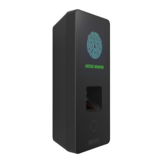
Download Print this page

Advertisement

COSEC ARGO
COSEC ARGO CAE200/ CAM200/ CAI200
COSEC ARGO FOE212/ FOM212/ FOI212
Contents
Assigning IP Address and Other Network Settings
Technical Specification
Please read this guide first for correct installation and retain it
for future reference. The information in this guide has been
authenticated at the time of publication. However, Matrix
Comsec reserves the right to make changes in product design
and specifications without prior notice.
3
7
7
8
9
11
17
23
2

Advertisement

loading
Need help?

Need help?

Do you have a question about the COSEC ARGO CAE200 and is the answer not in the manual?

Questions and answers

Summary of Contents for Matrix COSEC ARGO CAE200

  • Page 1: Table Of Contents

    Please read this guide first for correct installation and retain it for future reference. The information in this guide has been COSEC ARGO FOE212/ FOM212/ FOI212 authenticated at the time of publication. However, Matrix Comsec reserves the right to make changes in product design and specifications without prior notice.
  • Page 2: Know Your Cosec Argo

    Rear View (Common for both Series) Know your COSEC ARGO Figure 2 The COSEC ARGO is available in two series with three different variants in each series as follows: 1) COSEC ARGO with variants FOE212, FOM212 and FOI212. 2) COSEC ARGO with variants CAE200, CAM200 and CAI200.
  • Page 3 Pre-Installation Safety Instruction 5. Do not install the device in outdoor areas which may be exposed to rain, cold and dust. You can do indoor installation or on the turnstile 1. Do not install the device in extremely hot temperature or under direct under the roof as shown in Figure 5.
  • Page 4: What Your Package Contains

    What your Package Contains For Concealed wiring in Wall Mounting/Flush Mounting, first draw out the sufficient length of the cables from the hole of the mounting plate. 1) COSEC ARGO Unit 6) Power Adapter 12VDC,2A 2) Flush Mounting Plate 7) Power Supply Cable (with DC Jack) For Non-concealed wiring in Wall Mounting;...
  • Page 5: Installation Instruction: Wall Mounting

    Installation Instruction: Wall Mounting Step 2: Drill the screw holes along the traced markings. Fix Wall Mounting plate with the supplied screws. Tighten the screws with screw driver. Step 1: Place the Wall Mounting plate and trace screw holes 1 and 2 on the wall where the device is to be installed.
  • Page 6 Step 3: Connect the cables of the ARGO unit and lead all the cables • Keep all the cables parallel to the side of the COSEC ARGO through the duct of the Wall Mounting plate into the electrical box body in such a way that it should not cover the back portion recessed in the wall i.e.
  • Page 7 Step 4: Align COSEC ARGO on the mounting plate and hook it Step 5: Insert the mounting screw into the mounting screw hole into the mounting slot. Press the bottom side inwards to lock it in at the bottom of the device. Tighten the screw to complete the place.
  • Page 8: Installation Instruction: Flush Mounting

    Installation Instruction: Flush Mounting Step 2: Place and fix the Flush Mounting plate with the supplied screws. Tighten the screws with screw driver. Step 1: Place the Flush Mounting Template on the desired installation surface. Mark the area along the dotted line and trace the four screw •...
  • Page 9 Step 3: Connect the cables of the ARGO unit and lead all the Keep all the cables parallel to the side of the COSEC ARGO • cables through the Flush Mounting plate into the electrical box body in such a way that it should not cover the back portion recessed in the wall.
  • Page 10 Step 5: Insert the mounting screw into the mounting screw hole Step 4: Align COSEC ARGO with the mounting plate and hook it at the bottom of the device. Tighten the screw to complete the into the mounting slot. Press the bottom side inwards to lock it Flush Mounting.
  • Page 11: Connecting The Cables

    Connecting the Cables For Concealed wiring; first draw out sufficient length of the • cables from the hole you have made on the mounting Micro USB surface. connector cable EM Lock Cable Ethernet Cable Connect the Power, External Reader and EM Lock cable •...
  • Page 12 Technical Specification Diode Connection for Back EMF Protection Event Buffer 5,00,000 Relay Relay Pin 1 Pin 2 Input Power 12V DC @2A and PoE Reader Power Max 12V DC @0.250 A Output Cathode Power Lock Reader Interface RS 232 and Wiegand Anode Type Reverse biased...
  • Page 13 FCC Compliance Technical Specification Thermal Sensor This device complies with part15 of the FCC rules. Operation is subject to the following two conditions: Operating 0 °C to +50 °C Temperature 1. This device may not cause harmful interference. 2. This device must accept any interference received, including Dimensions 186mm x 74mm x 50mm (Wall Mount) interference that may cause undesired operation.
  • Page 14 If you are unable to dispose-off the products or unable to locate e-waste recyclers, you may return the products to Matrix Return Material Authorization (RMA) department. MATRIX COMSEC PVT LTD Head Office...