Advertisement
Table of Contents
- 1 Table of Contents
- 2 Know Your VEGA Controller
- 3 Installing Card Personality Module
- 4 What's Your Package Contains
- 5 Things You will Need
- 6 Installation Instructions
- 7 Connecting the Cables
- 8 Connecting to the COSEC Server
- 9 Technical Specifications
- 10 Wifi and Bluetooth Specifications
- Download this manual
Advertisement
Table of Contents

Related Manuals for Matrix COSEC VEGA FOT


Summarization of Contents
Pre-Installation Safety Instructions
Avoid Extreme Temperatures and Sunlight
Avoid hot temperatures and direct sunlight to protect the LCD and fingerprint sensor.
Mounting Surface and Location
Mount on flat surfaces near access points like walls or elevators, using surface or concealed wiring.
Recommended Mounting Height
The recommended height from ground level is up to 4.5 feet.
Unsuitable Installation Environments
Avoid unstable surfaces, volatile materials, gas, or areas with static, magnetic fields, or noise.
Outdoor Installation Precautions
Do not install in outdoor areas exposed to rain, cold, or dust; opt for indoor or sheltered installation.
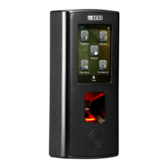
Know Your VEGA Controller
Device Overview and Variants
Overview of the VEGA Controller, its touch screen, finger sensor, card sensing area, and available variants.
Installing Card Personality Module
Removing and Preparing the Device
Remove the back cover by unscrewing it to access the CPM slot.
Inserting the Card Personality Module
Insert the module into the CPM slot with the correct orientation until it locks into place.
Completing Module Installation
Replace the back cover after the module is secured.
Important Safety Precautions
Installation and Servicing Guidelines
Installation by qualified technicians only; avoid opening covers due to shock hazard; use as intended.
Installation Instructions
Prepare Mounting Plate
Trace screw holes A and B, and optional opening C, on the mounting plate and drill accordingly.
Mounting Plate Installation
Fix the mounting plate securely using supplied screw grips and screws.
Cable Connection and Routing
Connect cables and route them through the designated hole into the electrical box or device bottom.
Device Mounting
Align the COSEC VEGA device with the mounting plate and slide it downwards to secure it.
Final Device Securing
Slide the device's back into the mounting slot and tighten screws at the bottom.
Connecting the Cables
Electrical Connections
Make electrical connections for Power, Exit Switch, EM Lock, Ethernet, AUX I/O, and External Reader per color codes.
Concealed Wiring Preparation
For concealed wiring, ensure sufficient cable length is drawn from the mounting surface hole.
Wiring Diagrams
Power and Exit Switch Connections
Details for connecting Power (CN1) and Exit Switch (CN2) with pin assignments and wire colors.
EM Lock and External Reader Wiring
Wiring details for EM Lock (CN3) and External Reader (CN6) including pinouts and wire colors.
Ethernet and AUX I/O Connections
Pin assignments and wire color mappings for Ethernet (CN4) and AUX I/O Connector (CN5).
Connecting to the COSEC Server
Assigning IP Address & Network Settings
Configure IP address, Subnet Mask, Gateway, DNS, Wi-Fi, and Mobile Broadband settings via web browser.
Basic Profile and Server Configuration
Select server (CENTRA/VYOM) and door type, then configure server URL, Port, and Tenant ID.
Technical Specifications
Device Specifications by Model
Comparison of Sensor, Credential Support, User Capacity, Card Type, USB, and Communication Ports for FAX, CAX, FAXQ, FOT.
Reader and Output Specifications
Details on Reader Interface Types and Reader Power Output for different VEGA models.
Additional Specifications
Lock and Output Relay Specifications
Specifications for Door Lock Relay, Door Lock Power, and Auxiliary Outputs Relay for different models.
Input Power and Connectivity Features
Details on Input Power, PoE, Built-in Wi-Fi, BLE, Battery Backup, and Operating Temperature.
WiFi and Bluetooth Module Details
Information on Model Name, Brand Name, EUT Type, Compliance, Frequency Range, Rated Power, and Mode.
FCC Compliance and Disposal
FCC Compliance Information
Information for users regarding FCC Part 15B compliance for Class A digital devices.
Product Compliance Standards
Compliance with EMC, Low Voltage, ROHS, BIS, Vibration, Shock, and IP rating standards.
End-of-Life Product Disposal
Guidelines for responsible disposal of electronic waste according to WEEE Directive.
Need help?
Do you have a question about the COSEC VEGA FOT and is the answer not in the manual?
Questions and answers