Advertisement
Quick Links
Advertisement

Related Manuals for Matrix COSEC NGT FCX


Summary of Contents for Matrix COSEC NGT FCX
- Page 1 COSEC NGT FCX The Next-Generation Terminal Quick Installation Guide...
- Page 2 Please read this guide first for correct installation and retain it for future reference. The information in this guide was current at the time of publication. However, Matrix Comsec reserves the right to make changes in product design and specifications without prior notice.
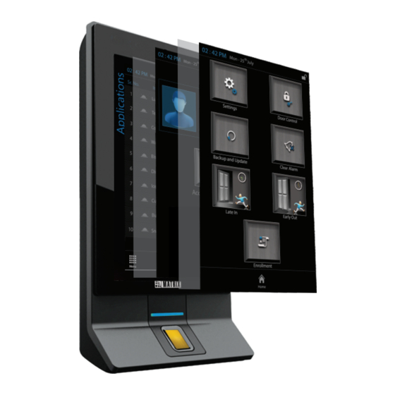
- Page 3 COSEC NGT FCX - Front View Camera TFT Display Capacitive Finger Sensor...
- Page 4 COSEC NGT FCX - Back View Card Reader Module Aux. Output Aux. Input RS-485 Exit Switch Door Lock Exit Reader...
- Page 5 COSEC NGT FCX - Bottom View Power Ethernet Slot to lock with Mounting Plate USB Ports (For Data Transfer, Firmware upgrade, Configuration upgrade, downloading event logs, Connecting 2G/3G Mobile Broadband dongle, Printer for Cafeteria Transactions) What Your Package Contains Ÿ COSEC NGT FCX Unit Ÿ...
-
Page 6: Mounting Options
Flush Mounting with Surface Wiring with Concealed Wiring Ÿ Decide what connections you need to make to the COSEC NGT FCX. Make sure all the necessary cabling is in place. NOTE ŸThis installation guide provides instructions only for Surface Mounting with Concealed Wiring. - Page 7 Ÿ Select a Location. It must be a flat surface such as a wall, close to the access point (door). Ÿ You can mount the COSEC NGT FCX on the wall surface or recessed in the wall. (See Mounting Options) Ÿ...
- Page 8 Ÿ Place the Mounting Plate on the installation surface. Ÿ Trace out the screw holes on the wall along the holes on the Mounting Plate (figure 1). Ÿ If required, trace out the rectangular hole of the Mounting Plate. Ÿ Remove the Mounting Plate. Ÿ...
-
Page 9: Connect The Cables
Step 2 Connect the Cables Ÿ If your wiring is from behind the surface/through an electrical box, first draw out sufficient length of the cables from rectangular hole you have cut on the mounting surface. ŸMake the electrical connections. Ÿ Refer the wire color code mapping for the terminals. CN1 External Reader Wire Color CN3 Exit Switch... - Page 10 Power ŸConnect the power adapter to the DC jack. Plug the adaptor into a power outlet. If connecting Matrix PSBB-Universal Mains Power Supply (13.8 VDC@2A) with battery backup to COSEC NGT, be sure to maintain correct polarity. CAUTION Do not apply Power to the unit until you have completed all the connections.
- Page 11 ŸTo use the 12VDC of the Door, short the terminals COM (CN2-1) and +ve (CN2- 4)as shown in figure 4, before connecting the NC/NO and the -ve terminal (CN2- 5 GND) to the Door lock. Door Magnet Using 12VDC of the DOOR Figure 4 Ÿ...
- Page 12 (figure 6). ŸAttach the COSEC NGT FCX to the mounting plate you fixed on the wall. If your wiring is not concealed, lead all the cables through the bottom of the...
- Page 13 Ÿ Match the mounting hooks (A, B, C, D, E) on the plate with the respective mounting slots (1, 2, 3, 4, 5) at the back of the device. Refer figure 7. Ÿ Tilt the device to allow mounting hook A into slot 1. Straighten the device and then slide it down on the plate (figure 8).
- Page 14 Figure 8...
- Page 15 Step 4 Power On COSEC NGT FCX ŸApply power to COSEC NGT FCX and wait for the reboot cycle to complete. Ÿ At power on, the LED will be turned glow blue accompanied by a long beep. Ÿ The Matrix Security Solutions logo will appear on the display.
- Page 16 Network Status Indications ICON LABEL COLOR MEANING Grey Ethernet Connection ON. Wi-Fi Connection available, but not Grey Wi-Fi connected to Wi-Fi Hotspot. Wi-Fi Connection available, and Wi-Fi Green connected to Wi-Fi Hotspot. Door is not connected to the Grey Server COSEC Server.
- Page 17 Status Indications for Events in Normal State LABEL MEANING ICON Late In Late In activated. Early Out Early Out activated. Door Lock Door Lock activated. Door Unlock Door Unlock activated. Alarm Alarm Activated...
- Page 18 Step 5 Connect the COSEC NGT FCX to the Network/COSEC Server The COSEC NGT FCX can be connected to the network over Ethernet, Wi-Fi, and Mobile Broadband. The COSEC NGT FCX is pre-configured with a default IP address and Subnet Mask.
- Page 19 ŸUse the keypad to enter the default Admin Password 1234. ŸTap OK. ŸOn the Admin screen, tap Settings, and then tap LAN. ŸTap the Door IP Address field, the keypad will appear. ŸUse the keypad to enter the IP Address you want to assign to the door. ŸTap Save.
- Page 20 Configuring Network Settings from the DOOR Web page Ÿ Connect a stand-alone computer/laptop to the Ethernet port of COSEC NGT FCX. Ÿ Open a web browser window on your computer/laptop. Ÿ Enter the default IP Address of the Door, http://192.168.50.1 in the address bar of the browser and press the Enter key on your computer keyboard.
- Page 21 ŸIf required, change the Subnet Mask, configure the Gateway IP Address, the Preferred and Alternate DNS. ŸNote down the MAC address of COSEC NGT FCX. You will need it to connect the device to the COSEC Server. ŸClick Submit to save your settings.
- Page 22 You can connect the COSEC NGT FCX either directly to the monitoring computer using an Ethernet Crossover/Straight cable. Crossover/Straight Cable COSEC Monitor PC You can connect the COSEC NGT FCX and the monitoring computer to an Ethernet Switch or hub using standard straight-through Ethernet cables. Ethernet Switch COSEC Monitor PC...
- Page 23 Configuring COSEC NGT FCX on the COSEC Server ŸOpen the COSEC Server application on a browser. ŸGo to Devices > Door > Add Door Ÿ In the Select Door Type list, select NGT Direct Door. ŸThe NGT Direct Door Parameters window will open.
- Page 24 Ÿ Create Users on the COSEC Server. Ÿ Assign Users to COSEC NGT FCX. Ÿ Enroll Users’ templates from the COSEC NGT FCX display or the web page or from the COSEC Server. Refer the COSEC NGT FCX User Guide for instructions on how to enroll users from the COSEC NGT FCX display and web page.
-
Page 25: Technical Specifications
Technical Specifications Credential Support Card + Finger + PIN User Capacity 10,000 Template Capacity 9600 Cards per User 2 (Any Type) Finger Sensor Module: SFM-3050, Sensor: TC1 3.2 Mega Pixel Camera 7” TFT Capacitive Speaker For Playing Greetings, Voice Guidance Messages Capacitive Touch Sense 1:1, 1:N... - Page 28 MATRIX COMSEC Head Office 394-GIDC, Makarpura, Vadodara - 390010, India Ph: +91 265 2630555, Fax: +91 265 2636598 Email: Info@MatrixComSec.com Customer Care Ph: +91 265 2630555 Email: Customer.Care@MatrixComSec.com www.MatrixComSec.com...
Need help?
Do you have a question about the COSEC NGT FCX and is the answer not in the manual?
Questions and answers