Advertisement
COSEC ARGO
COSEC ARGO CAE200/ CAM200/ CAI200
COSEC ARGO FOE212/ FOM212/ FOI212
Contents
Assigning IP Address and Other Network Settings
Technical Specification
Please read this guide first for correct installation and retain it
for future reference. The information in this guide has been
authenticated at the time of publication. However, Matrix
Comsec reserves the right to make changes in product design
and specifications without prior notice.
3
7
7
8
9
11
17
23
2
Advertisement

Related Manuals for Matrix COSEC ARGO FOM212


Summarization of Contents
Know Your COSEC ARGO
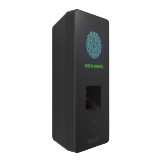
Front View of COSEC ARGO Variants
Details the front view of ARGO variants, showing touch screen, finger sensor, and card sensing area.
Rear View of COSEC ARGO
Illustrates the rear view of the COSEC ARGO, common to all series, showing mounting plates.
Bottom View of COSEC ARGO
Shows the bottom view, highlighting mounting screw holes and knock-out areas for wiring.
Preparation for Installation
Wall Mounting Preparation
Guidance on selecting a suitable flat surface near the access point for wall mounting.
Flush Mounting Preparation
Instructions for selecting a wooden door or location for flush mounting and making the necessary duct.
Wiring Considerations for Installation
Details on handling concealed and non-concealed wiring, and EM Lock connection with a diode.
Installation Instruction: Wall Mounting
Step 1: Place and Trace Wall Mounting Plate
Place the wall mounting plate, trace screw holes 1 and 2 on the wall for installation.
Step 2: Drill Holes and Fix Wall Mounting Plate
Drill screw holes along markings and fix the wall mounting plate with supplied screws.
Step 3: Connect Cables for Wall Mounting
Connect cables through the duct into the electrical box for concealed or non-concealed wiring.
Step 4: Align and Hook COSEC ARGO
Align COSEC ARGO on the mounting plate and hook it into the mounting slot, pressing to lock.
Step 5: Secure COSEC ARGO with Mounting Screw
Insert and tighten the mounting screw at the bottom of the device to complete wall mounting.
Installation Instruction: Flush Mounting
Step 1: Place Flush Mounting Template and Mark
Place the flush mounting template, mark the area and four screw holes (A,B,C,D).
Step 2: Drill Area and Fix Flush Mounting Plate
Drill the marked area and holes, then fix the flush mounting plate with screws.
Step 3: Connect Cables for Flush Mounting
Connect cables through the flush mounting plate into the recessed electrical box in the wall.
Step 4: Align and Hook COSEC ARGO for Flush Mount
Align COSEC ARGO with the mounting plate, hook into the slot, and press to lock.
Step 5: Secure COSEC ARGO for Flush Mount
Insert and tighten the mounting screw at the bottom of the device to complete flush mounting.
Connecting the Cables
COSEC ARGO Cable Connection Overview
Connect Power, External Reader, EM Lock cables to the 20 PIN connector and Ethernet to LAN port.
Power Cable (CN1) Connections
Details the GND and +12VDC IN connections for the power cable (CN1).
External Reader Cable (CN2) Connections
Specifies pin assignments for the External Reader cable (CN2) including data, LEDs, and RS232.
EM Lock Cable (CN3) Connections
Lists pin assignments for EM Lock cable (CN3), including switch inputs and relay outputs.
Diode Connection for Back EMF Protection
Explains connecting an overswing diode in reverse bias parallel to the EM Lock for protection.
Need help?
Do you have a question about the COSEC ARGO FOM212 and is the answer not in the manual?
Questions and answers