
Related Manuals for Aerotech ALS1000 Series


Summary of Contents for Aerotech ALS1000 Series
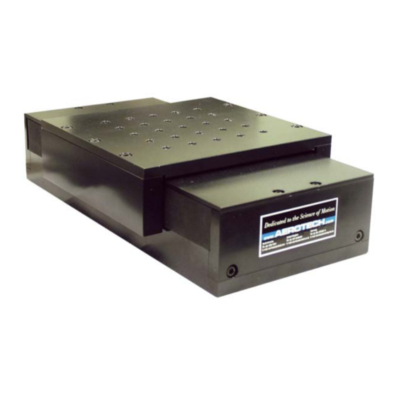
- Page 1 ALS1000 Series Stage User’s Manual P/N: EDS125 (Revision 1.04.00) Dedicated to the Science of Motion Aerotech, Inc. 101 Zeta Drive, Pittsburgh, PA, 15238 Phone: 412-963-7470 Fax: 412-963-7459 www.aerotech.com...
- Page 2 March 30, 2010 Revision 1.02.00 May 19, 2009 Revision 1.01.00 October 10, 2007 Revision 1.00.00 April 10, 2007 Product names mentioned herein are used for identification purposes only and may be trademarks of their respective companies. © Aerotech, Inc. 2011...
-
Page 3: Table Of Contents
ALS1000 Series Stage User's Manual Table of Contents Table of Contents Table of Contents List of Figures List of Tables Chapter 1: Overview 1.1. Standard Features 1.1.1. Optional Features 1.1.2. Home Markers 1.1.3. Model Numbers 1.2. Dimensions 1.3. Safety Procedures and Warnings 1.4. - Page 4 Table of Contents ALS1000 Series Stage User's Manual www.aerotech.com...
-
Page 5: List Of Figures
ALS1000 Series Stage User's Manual List Of Figures List of Figures Figure 1-1: ALS1000 Series Linear Positioning Stage in an XY Configuration Figure 1-2: Typical ALS1000 Stage with Callouts Figure 1-3: ALS1000 Option Example (with a nickel finish) Figure 1-4:... - Page 6 List of Figures ALS1000 Series Stage User's Manual www.aerotech.com...
-
Page 7: List Of Tables
ALS1000 Series Stage User's Manual List of Tables List of Tables Table 1-1: CW and CCW Home Marker Offset from Center of Travel Table 1-2: Model Numbering System Table 3-1: Environmental Specifications Table 3-2: ALS1000 Series Specifications Table 3-3: ALS1000 Motor Specifications... - Page 8 List of Tables ALS1000 Series Stage User's Manual viii www.aerotech.com...
-
Page 9: Chapter 1: Overview
ALS1000 Series Linear Positioning Stage in an XY Configuration N O T E : Aerotech continually improves its product offerings, and listed options may be superseded at any time. Refer to the most recent edition of the Aerotech Motion Control Product Guide for the most current product information at www.aerotech.com. -
Page 10: Standard Features
Overview ALS1000 Series Stage User's Manual 1.1. Standard Features The ALS1000 is a compact, high-performance stage for use in applications where a small footprint and envi- ronmental protection are required. The linear motor is completely cog-free, allowing for extremely tight veloc- ity control. -
Page 11: Optional Features
ALS1000 Series Stage User's Manual Overview 1.1.1. Optional Features In single- and two-axis systems, the Cable Management Systems are completely internal to the stages. How- ever, external CMS is available for three-axis systems. Custom configurations are common and readily avail- able, contact Aerotech for more details. -
Page 12: Home Markers
Overview ALS1000 Series Stage User's Manual 1.1.2. Home Markers The ALS1000 has three options for Home Marker location: center of the stage (-CM), counterclockwise end of the stage (-CCWM), and clockwise end of the stage (-CWM). These locations are defined with reference to the stage connectors. -
Page 13: Model Numbers
ALS1000 Series Stage User's Manual Overview 1.1.3. Model Numbers The stage model number indicates the optional features on a particular stage. To determine the options on your stage, refer to Table 1-2 for an explanation of the numbering system. Table 1-2:... - Page 14 Overview ALS1000 Series Stage User's Manual Table 1-2: Model Numbering System (continued) Linear Encoders -LT10X50 Linear encoder for ALS10010; 0.1 micron line driver output -LT15X50 Linear encoder for ALS10015; 0.1 micron line driver output -LT20X50 Linear encoder for ALS10020; 0.1 micron line driver output -LT30X50 Linear encoder for ALS10030;...
-
Page 15: Dimensions
ALS1000 Series Stage User's Manual Overview 1.2. Dimensions Figure 1-5: ALS1000 Dimensions www.aerotech.com Chapter 1... - Page 16 Overview ALS1000 Series Stage User's Manual Figure 1-6: ALS1000 XY Dimensions Chapter 1 www.aerotech.com...
-
Page 17: Safety Procedures And Warnings
ALS1000 Series Stage User's Manual Overview 1.3. Safety Procedures and Warnings The following statements apply throughout this manual. Failure to observe these precautions could result in serious injury to those performing the procedures and damage to the equipment. This manual and any additional instructions included with the stage should be retained for the lifetime of the stage. - Page 18 Overview ALS1000 Series Stage User's Manual Do not expose the stage to environments or conditions outside the specified range of oper- ating environments. Operation in conditions other than those specified can cause damage to the equipment. The stage must be mounted securely. Improper mounting can result in injury and damage to the equipment.
-
Page 19: Ec Declaration Of Incorporation
ALS1000 Series Stage User's Manual Overview 1.4. EC Declaration of Incorporation Manufactorer: Aerotech, Inc. 101 Zeta Drive Pittsburgh, PA 15238 herewith declares that the product: Aerotech, Inc. ALS1000 Stage is intended to be incorporated into machinery to constitute machinery covered by the Directive 2006/42/EC as amended;... - Page 20 Overview ALS1000 Series Stage User's Manual Chapter 1 www.aerotech.com...
-
Page 21: Chapter 2: Installation
All ALS1000 series stages are packaged with shipping clamps installed to prevent stage table movement. These are red anodized brackets (the only red anodized pieces Aerotech uses) that bolt the stage table to the base. These must be removed before the stage table can be moved. For the ALS1000 series, these shipping clamps are internal to the stage. -
Page 22: Preparing The Mounting Surface
The mounting surface should be flat and have adequate stiffness in order to achieve the maximum per- formance from the stage. When an ALS1000 series stage is mounted to a non-flat surface, the stage can be distorted as the mounting screws are tightened (see Figure 2-1 and Figure 2-2). - Page 23 ALS1000 Series Stage User's Manual Installation Figure 2-2: Mounting to a Curve Surface N O T E : The stage housing is precision machined and verified for flatness prior to stage assembly at the factory. If necessary, machining should be performed on the mounting surface rather than the stage hous- ing to achieve a required flatness.
-
Page 24: Securing The Stage To The Mounting Surface
Installation ALS1000 Series Stage User's Manual 2.3. Securing the Stage to the Mounting Surface To access the mounting holes of the stage, the hardcover must be removed. Four screws, two at each end of the stage, retain the hardcover (see Figure 2-3). Remove the screws and slide the hardcover out from under the table. - Page 25 ALS1000 Series Stage User's Manual Installation Once the stage has been secured to the mounting surface, the hardcover must be reattached. Take special care to reattach the hardcover in the same orientation as it was removed (align the adhesive strip on the under- side of the hardcover with the blue ribbon cable within the stage).
-
Page 26: Attaching The Payload To The Stage
Installation ALS1000 Series Stage User's Manual 2.4. Attaching the Payload to the Stage To prevent damage to delicate payloads, test the operation of the stage before attaching the payload to the stage table. Proceed with the electrical installation and test the motion control system in accordance with the system documentation. -
Page 27: Electrical Installation
Electrical installation requirements will vary depending on stage options. Installation instructions in this sec- tion are for stages equipped with standard Aerotech motors intended for use with an Aerotech motion control system. Contact Aerotech for further information regarding stages that are otherwise configured. - Page 28 Installation ALS1000 Series Stage User's Manual Chapter 2 www.aerotech.com...
-
Page 29: Chapter 3: Operating Specifications
Altitude Operating: 0 to 2,000 m (0 to 6,562 ft) above sea level Contact Aerotech if your specific application involves use above 2,000 m or below sea level. Vibration Use the system in a low vibration environment. Excessive floor or acoustical vibration can affect stage and system performance. -
Page 30: Basic Specifications
Operating Specifications ALS1000 Series Stage User's Manual 3.2. Basic Specifications Basic ALS1000 series positioning stage specifications are shown in Table 3-2. Motor specifications are listed in Table 3-3. Table 3-2: ALS1000 Series Specifications Basic Model ALS10010 ALS10015 ALS10020 Total Travel... - Page 31 ALS1000 Series Stage User's Manual Operating Specifications Table 3-2: ALS1000 Series Specifications (continued) Basic Model ALS10030 ALS10045 Total Travel 300 mm (12 in) 450 mm (18 in) Drive System Linear Brushless Servomotor (BLMC-142-A) Feedback Noncontact Linear Encoder Resolution (LT) 0.005 µm - 1.0 µm (0.2 µin - 40 µin)
-
Page 32: Table 3-3: Als1000 Motor Specifications
(6) Maximum winding temperature is 125 °C (7) Ambient operating temperature range: 0 °C - 25 °C, consult Aerotech for performance in elevated ambient temperatures (8) All Aerotech amplifiers are rated Apk; use torque constant in N-m / Apk when sizing Chapter 3 www.aerotech.com... -
Page 33: Load Capability
If a cantilevered load situation is used, first determine if it is a vertical cantilever or side cantilever system based on Figure 3-2. Measure the cantilever length, then find the corresponding load value from Fig- ure 3-1. Figure 3-1: Load Capability of ALS1000 Series Stages www.aerotech.com Chapter 3... - Page 34 Operating Specifications ALS1000 Series Stage User's Manual Figure 3-2: Stage Orientations for L and L Chapter 3 www.aerotech.com...
-
Page 35: Magnetic Actuator Limit
ALS1000 Series Stage User's Manual Operating Specifications 3.4. Magnetic Actuator Limit 3.4.1. Actuator Limit Operation Each actuator limit has a magnet which is detected by the encoder read head. Each actuator is mounted at the ends of the stage table perpendicular to the direction of table motion. When movement of the stage table detects the magnet, a limit signal is generated. -
Page 36: Standard Motor Wiring
For reference, connector pin assignments and general wiring information is given in the following figures. Pin assignements are defined in Table 3-5. N O T E : Refer to the other documentation accompanying your Aerotech equipment. Call your Aerotech rep- resentative if there are any questions on system configuration. -
Page 37: Vacuum Operation
ALS1000 Series Stage User's Manual Operating Specifications Table 3-5: Limit/Motor Wiring Pin Output Descriptions Pin Output Description + LMT Active high signal indicating maximum travel produced by positive stage direction. Cosine. Incremental encoder output; either TTL line driven or amplified sine wave type signal. - Page 38 Operating Specifications ALS1000 Series Stage User's Manual Chapter 3 www.aerotech.com...
-
Page 39: Chapter 4: Maintenance
4.1. Service and Inspection Schedule Lubricant inspection and replenishment in ALS1000 series stages depends on conditions such as duty cycle, speed, and the environment. An inspection interval of once per month is recommended until a trend develops for the application. -
Page 40: Cleaning And Lubrication
4.2.2. Important Notes on Lubrication When cleaning and/or lubricating components of the ALS1000 series stages: 1. Be sure to use a clean, dry, soft, and lint–free cloth for cleaning. 2. Take the opportunity during the lubrication procedure to inspect the linear motion guides for any damage or signs of wear. -
Page 41: Lubrication And Cleaning Process
ALS1000 Series Stage User's Manual Maintenance 4.2.3. Lubrication and Cleaning Process The lubrication and cleaning process is outlined in the steps that follow. 1. Drive the stage table to one end of travel and remove power to the stage. 2. Remove the screws on the edges of the hard cover (as shown in Section 2.3. ) and slide it out from under the stage. - Page 42 Maintenance ALS1000 Series Stage User's Manual Chapter 4 www.aerotech.com...
-
Page 43: Appendix A: Warranty And Field Service
Aerotech makes no warranty that its products are fit for the use or purpose to which they may be put by the buyer, where or not such use or purpose... - Page 44 Aerotech will provide an on-site field service representative in a reasonable amount of time, provided that the customer issues a valid purchase order to Aerotech cov- ering all transportation and subsistence costs. For warranty field repairs, the cus- tomer will not be charged for the cost of labor and material.
-
Page 45: Appendix B: Technical Changes
ALS1000 Series Stage User's Manual Technical Changes Appendix B: Technical Changes Table B-1: Current Changes (Revision 1.04.00) Section Change Section 1.4. Added section Section 3.1. Added section Chapter 2: Installation, Section 2.1. , Section 2.3. , Changed base width to 5.95" from 6.00"... -
Page 46: Table B-2: Archive Of Changes
Technical Changes ALS1000 Series Stage User's Manual Table B-2: Archive of Changes Version Section Change 1.00.00 New manual 1.01.00 Section 2.3. Directions for reattaching the hardcover expanded 1.02.00 Section 1.2. Added Dimensions section 1.02.00 Section 1.1.2. Added Home Marker section 1.02.00... -
Page 47: Index
Index ALS1000 Series Stage User's Manual Index safety procedures Service schedule Attaching the Payload stage table Standard Features cable Unpacking and Handling the Stage Declaration of Incorporation Dimensions Warnings wiring 19, 27 Electrical Installation encoders 19, 28 Environmental Specifications Inspection schedule... - Page 48 ALS1000 Series Stage User's Manual Index Index www.aerotech.com...
-
Page 49: Reader's Comments
Reader's Comments ALS1000 Series Stage Manual P/N: EDS125, February 28, 2011 Revision 1.04.00 Please answer the questions below and add any suggestions for improving this doc- ument. Is the manual: Adequate to the subject Well organized Clearly presented Well illustrated How do you use this document in your job? Does it meet your needs? What improvements, if any, would you like to see? Please be specific or cite examples.
Need help?
Do you have a question about the ALS1000 Series and is the answer not in the manual?
Questions and answers