Aerotech ALAR100LP Manuals
Manuals and User Guides for Aerotech ALAR100LP. We have 3 Aerotech ALAR100LP manuals available for free PDF download: Hardware Manual
Aerotech ALAR100LP Hardware Manual (64 pages)
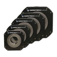
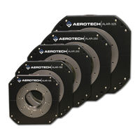
Large Aperture Rotary Stage
Brand: Aerotech
|
Category: Industrial Equipment
|
Size: 6 MB
Table of Contents
Advertisement
Aerotech ALAR100LP Hardware Manual (64 pages)
Brand: Aerotech
|
Category: Industrial Equipment
|
Size: 2 MB
Table of Contents

Aerotech ALAR100LP Hardware Manual (54 pages)
Large Aperture Low-Profile Rotary Stage
Brand: Aerotech
|
Category: Industrial Equipment
|
Size: 2 MB
Table of Contents
Advertisement