RADEMACHER ReWiSo 2696 Instruction Manual For The Electrical Connection And For Commissioning
Source: rademacher.de
Hide thumbs
Also See for ReWiSo 2696:
- Installation and operating instructions manual (232 pages) ,
- Additonal operating & safety instructions (37 pages)

Related Manuals for RADEMACHER ReWiSo 2696


Summary of Contents for RADEMACHER ReWiSo 2696
- Page 1 ReWiSo 2696 Instruction manual for the electrical connection and for commissioning Item no.: 3100 00 14 VBD 549-2 (05.21)
-
Page 2: Dear Customer
Dear Customer, ...Congratulations on purchasing the ReWiSo, you have opted for a quality product manufactured by RADEMACHER. Thank you for the trust you have placed in us. This manual..describes how to install, connect and operate the ReWiSo. Before you begin, please read this manual through completely and follow all the safety instructions. -
Page 3: Table Of Contents
Contents Dear Customer, ...........2 Installation of the weather station and connection of the drive .....30 This manual..........2 Location ............30 Key to symbols ...........2 Fitting the bracket ........30 Contents ............3 Preparation of the weather station....31 Connection of the power supply and drive ..32 Description ..........4 Installation of the weather station ....33 Included in delivery ........4... -
Page 4: Description
Description ReWiSo has been developed for automatic control and convenient manual operation of an awning or Venetian blind. The controller has a very high degree of flexibility for connection and adjustment and can therefore be adapted individually to different instal- lation conditions. -
Page 5: Available Automatic Functions In Overview
Description Available automatic functions in overview u Shading according to sun intensity with extension and retraction delay u Extension to a programmed position in the case of adjustable Venetian blinds also with setting of the slat angle u Blocking of sun shading until a preselected indoor temperature is reached (heat containment, only in automatic mode - energy-saving function) u Retraction of sun shading below a preselected outdoor temperature (frost protection, only in automatic mode) -
Page 6: Operation
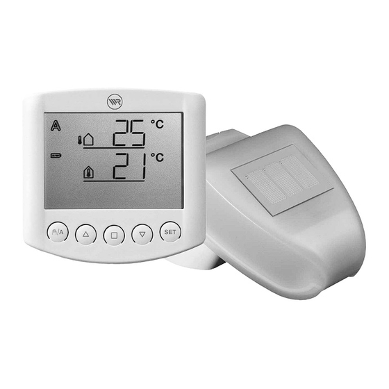
Operation Button assignment and display symbols on the weather data display Automatic Outdoor mode temperature Manual Indoor Battery temperature Rain alarm Wind alarm Manual/ Stop Down Setting Automatic In the normal function, the operating unit of the controller displays the current outdoor temperature (top line) and indoor temperature (bottom line), as well as the operating mode (automatic or manual), the battery charge state and current alarm message for rain or wind. -
Page 7: Display Of Brightness And Wind Velocity
Operation Automatic mode active Manual mode active. The connected drive was operated manually (with the arrow buttons) or the button was pressed. The automatic functions are thus deactivated and the awning or Venetian blind is not controlled according to brightness or temperature. The safety functions ‘Rain alarm’ and ‘Wind alarm’ remain active. -
Page 8: Manual Operation
Operation Manual operation Manual control, pre-setting of the automatic functions and the basic setting of the connected sun shading are performed with the buttons on the operating unit. Stop Down The connected awning or Venetian blind can be operated by hand using the buttons . -
Page 9: Setting The Automatic Functions
Setting the automatic functions In order that the awning or Venetian blind provides optimum sun shading, the values for automatic mode have to be adapted to the conditions on site. The following settings can be made in turn: A. Brightness for the sun shading B. - Page 10 Setting the automatic functions You are in the automatic settings Exit Confirm/ Next You can exit the automatic settings at any time by pressing the button. The changes made to the values are then not saved. If no button is pressed in the automatic settings for 5 minutes, the display automatically switches back to the temperature display.
-
Page 11: A Brightness For The Sun Shading
A. Brightness for the sun shading In the automatic settings, first enter the brightness above which the sun shading should be extended. The sun intensity is displayed in kilolux (kLux). The value 1 kLux is achieved even with an overcast sky, 20 kLux is achieved when the sun is just coming out and 100 kLux is achieved with a cloudless sky at midday. -
Page 12: B Extension Delay
B. Extension delay After setting the brightness, now enter the delay time for the extension of the sun shading. This delay ensures that the sun shading does not constantly extend and retract in the event of rapidly changing light conditions. The default setting for the extension is 1 minute. -
Page 13: D Indoor Temperature Lock
C. Retraction delay (lower). Then press SET to proceed to the Adjust the value with (higher) and setting of the next parameter. D. Indoor temperature lock After setting the retraction delay, now enter the indoor temperature below which the extension of the sun shading is to be blocked. Using the indoor temperature lock, you can use the heat of the sun to achieve the desired room temperature (e.g. -
Page 14: E Outdoor Temperature Lock
E. Outdoor temperature lock After setting the indoor temperature lock, now enter the outdoor temperature below which the sun shading should not be moved. The outdoor temperature lock is important when sun shading is installed on the outside of the building. In the event of frost, the awning or Venetian blind can freeze in the guide rails. -
Page 15: F Wind Alarm
Wind alarm After setting the outdoor temperature lock, now enter the value for the wind alarm function. The wind alarm protects outdoor sun shading against damage. If the entered wind value is exceeded, the awning or Venetian blind is retracted and manual operation is blocked. The wind velocity is entered in m/s (metres per second). -
Page 16: G Rain Alarm
Wind alarm Table: Wind velocity Description km/h Beaufort Knots Calm < 0.3 < 1.1 < 1 Almost calm 0.3 - 1.5 1.1 - 5.4 1 - 3 Very light wind 1.6 - 3.3 5.5 - 11.9 4 - 6 Light wind 3.4 - 5.4 12.0 - 19.4 7 - 10... -
Page 17: H Saving The Automatic Settings
H. Saving the automatic settings At the end of the input of the automatic settings, (Save) is displayed to prompt saving of the entered settings. Press the SET button to save your inputs and return to the weather data display. Press to exit the automatic settings without saving. -
Page 18: Basic Setting
Basic setting During commissioning of the controller, the basic device settings are entered here. The following settings can be made in turn: 1. Radio connection to the weather station 2. Rotation direction of the motor 3. Running direction 4. Travel command in the event of a wind or rain alarm 5. - Page 19 Basic setting You are in the basic settings Edit Exit Confirm/ Next You can exit the basic settings at any time by pressing the button. The changes made to the settings are then not saved. If no button is pressed in the basic settings for 5 minutes, the display automatically switches back to the temperature display.
-
Page 20: Radio Connection To The Weather Station
1. Radio connection to the weather station The first step is the teach-in (or later also clearing) of the radio connection. The teach-in may only be carried out by a qualified electrician as the programming button is inside the weather station. Select the desired step with the button: (Continue) to skip this step,... -
Page 21: Rotation Direction Of The Motor
2. Rotation direction of the motor After teaching-in the radio connection, now set the rotation direction of the motor. If the ‘Up’ and ‘Down’ cables were connected incorrectly during installation of the drive, this can be corrected in this step. For the rotation direction test, first extend the sun shading slightly. -
Page 22: Running Direction
3. Running direction After setting the rotation direction of the motor, now select whether the sun shading extends from top to bottom or from bottom to top. Sun shading can extend from the top or bottom depending on the model. In this step you can change the assignment of the arrow buttons so that these correspond to the running direction of the sun shading. -
Page 23: Travel Command In The Event Of A Wind Or Rain Alarm
4. Travel command in the event of a wind or rain alarm After setting the running direction, you can now select whether the travel command is to be limited in time or continuous in the event of a wind or rain alarm. If a wind or rain alarm is triggered, the sun shading is retracted. -
Page 24: Transmission Of The Weather And Automatic Data
5. Transmission of the weather and automatic data Press the button to switch between the OFF and ON displays. Select: In order not to send weather data and automatic commands (setting for normal awning and Venetian blind controllers). Press the SET button to proceed to the next setting step. -
Page 25: Sun Shading Position
6. Sun shading position After setting the running direction, you can now teach-in a sun shading position. An individual position can be set for awnings or Venetian blinds up to which the sun shading is extended in automatic mode. With adjustable Venetian blinds, the opening angle of the slats can also be set (reversing). -
Page 26: Retracted Position
6.1. Retracted position After confirming (Learn), the prompt (Open) appears. First fully retract the awning or Venetian blind so that it provides no sun shading. Then press the SET button to proceed to the next step. 6.2. Setting the desired position The prompt (Close) appears. -
Page 27: Slat Angle
6.3. Slat angle The prompt (Reverse) appears. With adjustable Venetian blinds, now open the slats to the desired angle. With awnings or if the Venetian blinds are not to be opened, do not move the sun shading. Then press the SET button to terminate the setting of the sun shading position. 7. -
Page 28: Safety Instructions For Automatic And Alarm Functions
Safety instructions for automatic and alarm functions In the event of a power failure at the weather station, the controller can no longer control the connected drives! If the full scope of functions is to be maintained even without the mains power supply, an emergency power generator with corresponding changeover from mains to emergency operation has to be installed on site. -
Page 29: Installation And Commissioning
RADEMACHER can assume no liability for amendments to the standards or regulations after publication of this operating manual. -
Page 30: Installation Of The Weather Station And Connection Of The Drive
Installation of the weather station and connection of the drive Location Select an installation position on the building where wind, rain and sun can be detected by the sensors without any impeding structures. No structural parts may be installed above the weather station from which water could drip onto the precipitation sensor after it has already stopped raining or snowing. -
Page 31: Preparation Of The Weather Station
Installation of the weather station and connection of the drive Preparation of the weather station 1 = Cover with rain sensor 2 = Cover latch 3 = PCB 4 = Lower housing section Unlock the cover and lift off from above The cover of the weather station with the rain sensor is latched at the lower edge on the left and right (see Fig.). -
Page 32: Connection Of The Power Supply And Drive
When connecting motors in parallel, check whether a group control relay is prescribed by the motor manufacturer. Group control relay can be ordered from RADEMACHER. If motors are connected in parallel that are not suitable for this, these and the controller will be damaged. -
Page 33: Installation Of The Weather Station
Installation of the weather station and connection of the drive Insert the cables for the power supply and the drive through the rubber seals on the underside of the weather station and connect the power supply (L1 / N / PE) and the drive (PE / N / Up / Down) to the corresponding terminals. -
Page 34: Notes On Installation Of The Weather Station
Installation of the weather station and connection of the drive Notes on installation of the weather station Do not open the weather station if water (rain) could get inside: Even a few drops of water could damage the electronics. Ensure it is connected properly. An incorrect connection can lead to destruction of the weather station and the control electronics. -
Page 35: Commissioning
Commissioning After wiring up the system and checking all connections, proceed as follows: u Switch on the mains power supply to the weather station. u Insert the batteries into the operating unit as described in the section “Inserting batteries”. u The display of the operating unit shows that no radio connection between the weather station and operating unit has been taught-in: u Hold the SET button depressed for 3 seconds until the following display appears: u Now hold the SET button depressed again for 3 seconds until the display... -
Page 36: Checking The Sensors
Commissioning You are in the basic settings. Continue as described in section 1 “Radio connection to the weather station” for the basic settings. u Then check the function of the sensors (see next section). Checking the sensors In the event of malfunctions of the sensors, error messages are displayed instead of the values. -
Page 37: Checking The Rain Sensor
Checking the sensors Checking the rain sensor Wet one or more of the golden sensor surfaces in the cover of the weather station. The symbol (rain alarm) appears on the display. For this to happen, the rain alarm must have been activated in the automatic settings (this is the default setting on delivery, see also the section “G. -
Page 38: Service / Maintenance And Care
Service / maintenance and care Weather station The weather station should be inspected for soiling twice a year and cleaned, as necessary. In the event of heavy soiling, the wind sensor may cease to function, display a constant rain alarm or no longer detect sunshine. In the event of a power failure, the data input by you is stored for approx. -
Page 39: Error Messages
Service Error messages Error messages may appear on the weather data display instead of the values for temperature, brightness or wind velocity. Error: A battery is displayed, but no other symbols or values. Manual operation is possible. Cause: The batteries in the operating unit are empty and have to be replaced. - Page 40 Service Error: instead of the outdoor temperature instead of the indoor temperature Cause: The outdoor temperature sensor of the weather station or the indoor temperature sensor in the operating unit is defective. Procedure: The error may only be remedied by a qualified electrician. Please contact your installer.
-
Page 41: Calling Up Service Data
Service Calling up service data The software version of the operating unit and weather station can be shown on the display. The service area can be called up from the basic settings by holding the SET button depressed (3 seconds). The software version of the operating unit ( is displayed first;... -
Page 42: Abbreviations
Abbreviations kLux: Kilolux (= 1000 Lux), unit of light intensity m/s: Metres per second, unit of wind velocity Error Deactivated, switched off Activated, switched on Save the entered settings Technical specifications Radio technology Transmission frequency: 868.2 MHz Transmission power: max. 10 mW Operating unit Operating voltage: 2 x 1.5 V (2 batteries, AA/Mignon/LR6) -
Page 43: Weather Station Connection Diagram
Weather station connection diagram Weather station Mains Sun shading Down Down Motor The operating unit is battery-operated. The communication between the operating unit and weather station is done by radio. -
Page 44: View Of The Rear Panel And Weather Station Drilling Pattern
View of the rear panel and weather station drilling pattern All dimensions in mm, technical deviations possible. Dimensions in mm... -
Page 45: View Of The Rear Panel And Operating Unit Drilling Pattern
View of the rear panel and operating unit drilling pattern All dimensions in mm, technical deviations possible. Dimensions in mm... -
Page 46: Control Of Several Drives As A Group
Control of several drives as a group NOTE Several drives can be controlled at the same time using the RADEMACHER Multiple Control Relay. Personal setting data for automatic mode Sun shading above brightness more than: kLux Delay time – extending: min. -
Page 47: Warranty Terms And Conditions
Warranty terms and conditions You can find information about the warranty conditions of our products on our homepage. - Page 48 RADEMACHER Geräte-Elektronik GmbH Buschkamp 7 46414 Rhede (Germany)
Need help?
Do you have a question about the ReWiSo 2696 and is the answer not in the manual?
Questions and answers