
Subscribe to Our Youtube Channel
Related Manuals for RADEMACHER Troll Basic 5602


Summary of Contents for RADEMACHER Troll Basic 5602
- Page 1 Troll Basic 5602 Instruction manual for the electrical connection and for commissioning Item no. 3650 01 12 (ultra-white) Type: 5602 VBD 599-2 (01.21)
-
Page 2: Table Of Contents
Contents These instructions..............4 Application of this manual ..............4 Hazard symbols ..............5 Levels of danger and signal words ..........5 Symbols and depictions used ............6 Safety Instructions .............7 Intended Use ..................8 Incorrect Use ..................8 Required Expert Knowledge of the Installer ......9 Glossary - Definition ................9 Included in delivery ............ - Page 3 Contents 11. Connecting a light sensor* ..........30 11.1 Light sensor connection when using the supplied frame . 30 11.2 Light sensor connection when using a frame supplied by a third-party manufacturer ........32 11.3 Dismantling the light sensor ............33 12.
-
Page 4: These Instructions
◆ This manual is a component of the product. Please store it in an easily accessible place. ◆ When passing the Troll Basic 5602 on to a third party, this manual must be passed on as well. ◆ Damage resulting from non-compliance with these instructions and safety instructions will void the guarantee. -
Page 5: Hazard Symbols
2. Hazard symbols The following hazard symbols are used in this instruction manual: Danger of fatal electric shock Danger area / dangerous situation 2.1 Levels of danger and signal words DANGER! This hazard will lead to serious injury or death if not avoided. WARNING! WARNING! This hazard may result in serious injury or death if not avoided. -
Page 6: Symbols And Depictions Used
2.2 Symbols and depictions used Depiction Description Procedures Itemisation ◆ 1) or a) Lists further useful information Please read the respective manual Indicator light flashes red Indicator light lights up red Indicator light is off... -
Page 7: Safety Instructions
3. Safety Instructions The use of defective equipment can lead to personal injury and damage to property (electric shocks / short circuiting). ◆ Never use defective or damaged equipment. ◆ Check the Troll Basic beforehand for damage. ◆ Consult our customer service department in the event that you discover damage, see page 54. -
Page 8: Intended Use
Improper use can lead to serious injuries or property damage. ◆ The Troll Basic 5602 is not suitable to be used for an electrically safe disconnection of the connected appliances. There is a risk to life caused through short circuiting and electric shocks if the troll Basic 5602 is used outside or in damp rooms. -
Page 9: Required Expert Knowledge Of The Installer
3.3 Required Expert Knowledge of the Installer The electrical connection, installation and commissioning of the Troll Basic 5602 must only be carried out by a qualified electrician in accordance with the instructions in this manual. 3.4 Glossary - Definition ◆ UW = ultra-white (device colour) DIN 49075 ◆... -
Page 10: Included In Delivery
4. Included in delivery Included in delivery a) 1 x Operating unit (50 x 50 mm) b) 1 x Frame c) 1 x Installation housing d) 1 x Spacer frame, see page 32 e) 1 x Instruction manual (not illustrated) After unpacking please check and compare... -
Page 11: General View Of The Operating Unit
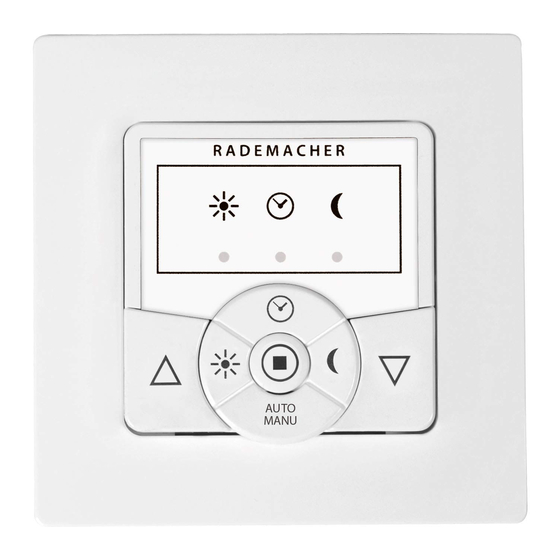
5. General View of the Operating Unit 2) 3) Pos. Symbol Description Operating unit Sun LED (red) Timer LED (red) Dusk LED (red) Timer button ◆ Switch the automatic timer on/off. Sun button ◆ Switch the automatic solar function on/off. Dusk button ◆... - Page 12 5. General View of the Operating Unit Pos. Symbol Description Up button ◆ Open the roller shutter or stop the current drive; see page 35. Down button ◆ Close the roller shutter or stop the current drive; see page 35. SET key ◆...
-
Page 13: General View Of The Installation Housing
5.1 General View of the Installation Housing Pos. Symbol Description Installation housing Plug-in coupling for the operating unit Claw fasteners and screws Connecting terminals Type plate... -
Page 14: Electrical Connections
Parallel connection of several devices is possible on both inputs. E1 / E2 and the Troll Basic 5602 must be connected to the same phase [ L ], see page 25. Voltage supply [ L / N ] 230 V / 50 Hz Connection of the supply voltage. -
Page 15: Function Of The Buttons And Leds
5.3 Function of the buttons and LEDs Function Button LED (red) up / stop / down / stop Switch automatic timer on / off 1 sec. > Switch the automatic solar 1 sec. > function on/off Switch automatic dusk function 1 sec. -
Page 16: Product Description
28. Installation and electrical connection The Troll Basic 5602 is designed as a flush-mounted device for indoor rooms. The electrical connection is carried out by means of the connecting terminals on the reverse side of the installation housing. -
Page 17: Compatible Switches
6.1 Compatible switches With the provided frame, the Troll Basic 5602 can be integrated into customary switches. Suitable switches can be found in the table below. Manufacturer Switch BERKER Arsys / K1 / S1 Busch-Duro 2000 Si / Reflex Si / alpha... -
Page 18: Overview Of Features
6.2 Overview of Features ◆ Manual operation on site up (s ) / stop / down (t ) / stop ● ◆ AUTO / MANU - switchover ◆ Switch automatic timer on / off Separate switching time for UP (s ) and DOWN (t ●... -
Page 19: Technical Specifications
7. Technical Specifications Mains supply [ L / N ] Mains supply voltage: 230 V / 50 Hz Consumption: Standby: < 0.6 W Connection of the tubular motor [ s and t ] Switching voltage: 230 V / 50 Hz Maximum switching ohmic load, e.g. - Page 20 ◆ Due to the small contact distance (µ), not suitable for disconnecting. ◆ The Troll Basic 5602 is not suitable to be used for an electrically safe disconnection of the connected tubular motor. Inputs [ E1 (s) / E2 (t) ] ...
- Page 21 7. Technical Specifications General information External dimensions (W x H x D) 50 x 50 x 12 mm operating unit [ 1 ]: according to DIN 49075 Available colours: Ultra-white (UW) Built-in depth: 32 mm Permissible ambient 0 °C to + 40 °C temperature range: Protection class: II (only for use in dry rooms)
-
Page 22: Factory Settings
7.1 Factory Settings Factory Settings Automatic mode: Automatic solar function: Automatic dusk function: 7.2 Conduct in the event of power failure After a power failure, the timer LED flashed and the timer stands still. Data retention following a power failure All settings (also the configured switching times) are retained after a power failure. -
Page 23: Important Information Prior To Electrical
Parallel connection of electronic tubular motors A maximum of 3 tubular motors can be connected in parallel to the Troll Basic 5602 (e.g. RADEMACHER electronic tubular motors). Parallel connection of mechanical tubular motors A cut-off relay is required in order to connect mechanical tubular motors in parallel. -
Page 24: Safety Instructions For The Electrical Connection
◆ Check that the system is de-energised. WARNING! WARNING! Short-circuiting, caused when the Troll Basic 5602 is overloaded, poses a danger to life. The maximum switching capacity must not be exceeded, for this, please observe the details in the Technical Specifications,... - Page 25 Troll Basic 5602 to be damaged. ◆ When the inputs [E1 / E2] are used, the external push- button / controller and the Troll Basic 5602 must be connected to the same phase [ L ]. ◆ If another phase [ L‘ ] is connected, the incorrect mains voltage (380 V / 50 Hz) will be applied to the inputs and damage the Troll Basic 5602.
- Page 26 9. Safety Instructions for the Electrical Connection Maximum cable length for the connection of external push-buttons ◆ The maximum length of lead to connect an external switch/ push button must not exceed 10 m. Length of insulation stripped: 6 mm All leads must be stripped to 6 mm.
-
Page 27: Connecting A Tubular Motor
5602 into the flush-mounted box is carried out, see page 29. Connecting the white set cord (SET) from RADEMACHER tubular motors The white set cord (SET) from RADEMACHER tubular motors must be connected to the neutral terminal [ N ] to ensure trouble-free operation of the tubular motor. -
Page 28: Connection Diagram With Tubular Motor
9.2 Connection Diagram with Tubular Motor Tubular motor Inputs E1 / E2 (230 V / 50 Hz), only if required. -
Page 29: Installation After The Electrical Connection
10. Installation after the Electrical Connection Insert the installation housing into the flush-mounted box and fasten it with the screws of the claw fasteners. Place the frame onto the installation housing. Subsequently, carefully insert the operating unit into the installation housing . Switch on the mains power supply again. -
Page 30: Connecting A Light Sensor
11. Connecting a light sensor* If you intend to operate your Troll Basic 5602 and the connected tubular motor according to brightness levels, then you must connect the optionally available RADEMACHER light sensor to the Troll Basic 5602. 11.1 Light sensor connection when using the supplied frame Carefully pull the operating unit off the installation housing. - Page 31 11.1 Light sensor connection when using the supplied frame ATTENTION! Excessive bending can damage the sensor cable. The sensor cable is a fibre optic cable. Avoid excessive bending or crushing of the sensor cable. Feed the sensor cable into the cable bushing in the frame and guide it out.
-
Page 32: Light Sensor Connection When Using A Frame Supplied By A Third-Party Manufacturer
11.2 Light sensor connection when using a frame supplied by a third-party manufacturer If the cable bushing of the operating unit is covered by the frame, then it will be necessary to fit the additionally provided spacer frame onto the rear of the operating unit. It may be necessary to use an intermediate frame 50 x 50 * (DIN 49075), depending on the respective switch range used. -
Page 33: Dismantling The Light Sensor
11.3 Dismantling the light sensor Carefully pull the operating unit off the installation housing. If the sensor cable has been fixed in place by means of the operating unit's engagement hooks, then it must first be released, for example, with the help of a 50 cent coin. Pull the light sensor plug out of the socket. -
Page 34: Important Information Regarding The Commissioning
Without set end points on the tubular motors, the roller shutter poses a risk of injury. ◆ Prior to initial commissioning of the Troll Basic 5602, it must be ensured that the end points are configured for the connected tubular motor. -
Page 35: Manual Operation
13. Manual Operation The manual operation of the Troll Basic 5602 can be carried out with the up (s ) and down (t ) buttons or via a push-button that is connected to one of the inputs [ E1 ( s ) / E2 ( t ) ]. -
Page 36: Automatic Mode
14. Automatic mode The Troll Basic 5602 features three automatic functions: ◆ Automatic timer ◆ Automatic solar function ◆ Automatic dusk function All of the automatic functions can be combined or individually enabled or disabled. The status of each automatic function is indicated by the respective LED. -
Page 37: Automatic Timer
15. Automatic timer The same switching times every day of the week You can set an opening and closing time for your Troll Basic 5602 which will apply to all days of the week. Once this time is reached, the roller shutters will open or close automatically. -
Page 38: Configuring An Opening And Closing Time
15.1 Configuring an opening and closing time Configure an opening time (s (e.g. at 8:00 hours) 1 sec. Simultaneously briefly press the buttons. The timer LED flashes and the roller shutter travels upwards. The automatic timer is now activated. Your roller shutters will open automatically every day at 8:00 AM. -
Page 39: Switching The Automatic Timer On / Off
15.2 Switching the automatic timer on / off If required, the automatic timer can be switched on or off at any time. 1 sec. Press and hold the timer button for approx. 1 second. Pay attention to the timer LED. Automatic timer OFF The previously configured switching times are stored. -
Page 40: Automatic Solar Function
To do this, the light sensor is secured to the window pane with a suction cup and then plugged into the Troll Basic 5602. Automatic solar function Automatic moving up and down of the roller shutter once a set limit is exceeded. - Page 41 16. Automatic solar function Automatic clearing After 20 mins After approx. 20 minutes, the roller shutter is automatically raised a small amount to uncover the sensor. If the sun continues to shine, then the roller shutter remains in this position. If the brightness decreases below the set limit, it returns to the upper end point.
-
Page 42: Automatic Solar Function; Configuring Sensitivity
16.1 Automatic solar function; configuring sensitivity The automatic solar function is switched on by setting or changing the sensitivity. Configure the brightness at the level which the blinds should be closed. Set the current brightness as set limit and switch on the automatic solar function. - Page 43 16.1 Automatic solar function; configuring sensitivity Rapid flashing If the current brightness value is outside the measuring range, the set limit is set to the measured range limit. You can switch the automatic solar function on and off as required. 1 sec.
-
Page 44: Automatic Dusk Function
◆ The automatic dusk function is activated. ◆ When dusk is detected for a minimum of 15 seconds. ◆ The light sensor has been mounted and plugged into the Troll Basic 5602. Automatic lowering At dusk, the roller shutters will lower to the lower end point after approx. - Page 45 17. Automatic dusk function If the roller shutters are to be lowered as a result of the automatic dusk function, then you must set the closing time to a time after dusk (see example). ◆ If an automatic closing command is given before dusk triggers, then the automatic dusk function will not be executed.
-
Page 46: Automatic Dusk Function; Configuration Of Sensitivity
17.1 Automatic dusk function; configuration of sensitivity The automatic dusk function is switched on by setting or changing the sensitivity. Configure the brightness at the level (dusk) which the blinds should be closed. Set current brightness (dusk) as set limit and switch on the automatic dusk function. - Page 47 17.1 Automatic dusk function; configuration of sensitivity Rapid flashing If the current brightness value is outside the measuring range, the set limit is set to the measured range limit. You can switch the automatic dusk function on and off as required.
-
Page 48: Dimming The Leds
18. Dimming the LEDs The Troll Basic 5602 is equipped with automatic dimming LEDs to reduce the light intensity (e.g. bedrooms). The LEDs dim as the roller shutters are lowered. To use this function, the overall running time of the roller shutter must be set. -
Page 49: Hardware Reset In The Event Of Unit Failure
Subsequently check that the Troll Basic 5602 is functioning correctly. If the Troll Basic 5602 is still not reacting, carry out a software reset (see page 50) and test the Troll Basic 5602 with the factory settings. -
Page 50: Erase All Settings, Software Reset
20. Erase all Settings, Software Reset If necessary, you can erase all of your settings and return the Troll Basic 5602 system to its original factory settings. Simultaneously press and hold the buttons for 4 seconds. Release the buttons,..subsequently all of the settings will be deleted. -
Page 51: Dismounting
21. Dismounting DANGER! There is a risk of fatal electric shocks when touching electrical components. ◆ Disconnect all phases of the mains power supply cable and secure it to prevent any reconnection. Check that the system is de-energised. Switch off the mains power, secure it from restarting, and check that the system is de-energised. -
Page 52: Simplified Eu Declaration Of Conformity
22. Simplified EU Declaration of Conformity RADEMACHER Geräte-Elektronik GmbH hereby declares that the Troll Basic 5602 complies with the Directives 2014/35/EU (Low- voltage direcive) and 2014/30/EU (EMC directive). The full text of the declarations of conformity is available at the following website: www.rademacher.de/ce... -
Page 53: Warranty Conditions
Proof of this must be provided by presenting a copy of the bill. RADEMACHER will remedy any defects that occur within the warranty period free of charge either by repair or by replacement of the affected parts or by supplying a new replacement unit or one to the same value. - Page 54 RADEMACHER Geräte-Elektronik GmbH Buschkamp 7 46414 Rhede (Germany) info@rademacher.de www.rademacher.de Service: * 30 seconds free of charge, subsequently Hotline 01807 933-171* 14 cents / minute from German fixed line Fax +49 2872 933-253 networks and max. 42 cents / minute from service@rademacher.de...
Need help?
Do you have a question about the Troll Basic 5602 and is the answer not in the manual?
Questions and answers