Table of Contents
Advertisement
Advertisement
Table of Contents

Related Manuals for Covidien Newport HT70


Summary of Contents for Covidien Newport HT70
- Page 1 Operator's Manual Newport HT70 Ventilator with Accessories Plus Model...
- Page 2 Reproduction, adaptation, or translation without prior written permission is prohibited, except as allowed under the copyright laws. The information in this manual is the sole property of Covidien and may not be duplicated without permission. Protected under U.S. Patent #7,654,802.
-
Page 3: Table Of Contents
Table of Contents Introduction Overview ..............1-1 Brief Device Description . - Page 4 3.7.3 DC Auto Lighter Power Adapter ........... . .3-17 3.7.4 Aequitron Remote Alarm Cable .
- Page 5 Ventilator Alarms Setting Alarms ............. . 6-1 6.1.1 Alarm Quickset .
- Page 6 Battery Operation Internal Dual Battery System ..........7-1 7.1.1 Power Pac Battery Pack .
- Page 7 Front Panel Membrane Buttons and Indicators ....... 9-5 Alarms ..............9-5 Hardware Requirements .
- Page 8 Page Left Intentionally Blank viii Operator’s Manual...
- Page 9 Newport HT70 Ventilator Bottom Panel Labeling........
- Page 10 Figure 6-2. Backup Ventilation ............... .6-6 Figure 7-1. ...
- Page 11 List of Tables Table 1-1. HT70 Ventilator Configurations ............1-4 Table 3-1. ...
- Page 12 Page Left Intentionally Blank Operator’s Manual...
-
Page 13: Overview
We know that ventilatory support is critical in emergency situations. But for many of our cus- tomers, it is also a part of their daily lifestyle. The Newport HT70 Ventilators offer home care users the expanded mobility that allows them to experience more freedom in their lives than many have known before. -
Page 14: Exceptional Mobility
Introduction The twin micro-piston pump’s ability to deliver a variable flow enables the ventilator to provide a full range of operating modes and breath types with servo-controlled, leak-compensated PEEP. Leak compensation helps to improve triggering and avoid auto-triggering when a leak is present. The ventilator may be used with an endotracheal tube, tracheal tube, face mask, nasal mask or prongs, or mouthpiece. -
Page 15: Travel Certified
Travel Certified 1.2.3 The Newport HT70 Ventilator has been tested for and meets requirements for use in helicopter and fixed wing transport and for use on commercial airlines. Before traveling, be sure to speak with your airline representative about their particular concerns and clear all of your equipment with them well before your departure. -
Page 16: Warnings, Cautions, And Notes
WARNING: The design of the Newport HT70 Ventilator, the operating and service manuals, and the labeling on the ventilator take into consideration that the purchase and use of the equipment is restricted to trained professionals, and that certain inherent characteristics of the ventilator are known to the operator. - Page 17 Warnings, Cautions, and Notes WARNING: Transport of patients with the Newport HT70 Ventilator requires that medical staff have a good working knowledge of the ventilator and methods for problem resolution. Proper emergency backup equipment must be immediately available during transport.
- Page 18 WARNING: Always plug the Newport HT70 Ventilator into an external power supply source whenever it is available, even when the ventilator is not in use, to keep the internal dual battery system fully charged and to ensure best battery performance. Check battery capacity on the front panel before detaching from external power.
- Page 19 WARNING: Always disconnect the external power supply prior to servicing. WARNING: After servicing the Newport HT70 Ventilator, it must pass the operational verification procedure (OVP) before it is returned to patient use. See the service manual. WARNING: Do not use electrically conductive breathing circuits. Always use clean and dry breathing circuits.
-
Page 20: General Cautions
Do not place liquids on or near the ventilator. Caution: Damage can occur if the Newport HT70 Ventilator is exposed to extreme temperatures. Do not store the HT70 in areas where it may be exposed to temperatures below -40°C (-40°F) or above 65°C (149°F). ... -
Page 21: Warranty Information
Covidien shall not be liable for errors contained herein or for incidental or consequential damages in connection with the fur- nishing, performance, or use of this material. - Page 22 Introduction Covidien Danmark A/S Covidien Deutschland Covidien ECE Covidien Finland OY GmbH Langebrogade 6E, 4 sal Galvahiho 7 / A Rahtitie 3 Technisches Service Center 1411 København 832104 Bratislava FI-01530 Vantaa Raffineriestr. 18 Danmark Slovakia Finland 93333 Neustadt/Donau [T] +45 702 753 50...
- Page 23 Contact Information Covidien Puerto Rico Covidien Russia Covidien Saglik A.S. Covidien South Africa Palmas Industrial Park 53 bld. 5 Dubininskaya Street Maslak Mahallesi Bilim Sokak Corporate Park North No: 5, Sun Plaza Kat: 2-3 Road 869 Km 2.0 Bdlg. #1...
- Page 24 Introduction Page Left Intentionally Blank 1-12 Operator's Manual...
-
Page 25: Overview Of Controls, Screens, And Connectors
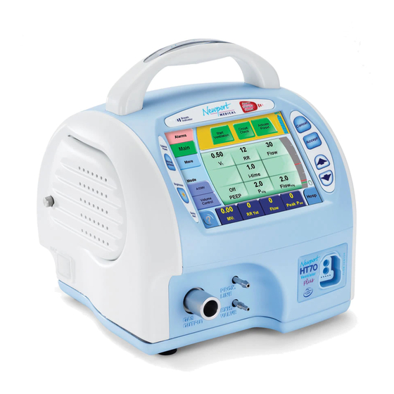
2 Overview of Controls, Screens, and Connectors Front Panel Overview The Newport™ HT70 Ventilator front panel consists of easy access membrane buttons, LED indi- cators, and the patient connection manifold. The center touch screen panel provides access to alarm and parameter settings. The HT70PM model has the added port for connecting the on- airway flow sensor. - Page 26 Overview of Controls, Screens, and Connectors Pac to the ventilator and then turn on the ventilator to verify the actual charge level percentage (shown in the message display). Proper care and maintenance of the internal dual battery system will ensure the longest life and best usage performance.
-
Page 27: Rear Panel Overview
Rear Panel Overview Rear Panel Overview Figure 2-2. Newport HT70 Ventilator Rear Panel Power Pac battery pack RS-232 output (external communication port to communicate with central monitoring systems) External power supply input Serial number label Remote alarm output On/off power switch (connects to nurse call systems) -
Page 28: Right Side Overview
Overview of Controls, Screens, and Connectors Right Side Overview Figure 2-3. Newport HT70 Ventilator (Right Side) Fresh gas intake port / oxygen accessories’ connection / optional oxygen accessories / bio-filter connection (allows attachment of the optional air oxygen entrainment mixer, low flow oxygen reservoir, or bio-filter) -
Page 29: Left Side Overview
Left Side Overview Left Side Overview Figure 2-4. Newport HT70 Ventilator (Left Side) Cooling fan cover (protects the internal fan) USB ports (2) (allow the attachment of optional accessories such as a flash drive for downloading the trends and event history files or uploading new software) -
Page 30: Bottom Panel Label
The bottom panel of the ventilator includes a label that contains information regarding agency approvals and power ratings. Here you will find the model number and manufacturing informa- tion. Figure 2-5. Newport HT70 Ventilator Bottom Panel Labeling Note: The serial number for the unit is located on the lower rear panel near the power switch. -
Page 31: Setup And Pre-Use Preparations
Remove all of the items from the shipping box and inspect each Newport™ HT70 Ventilator part and component for completeness. Verify that there is no shipping damage. To obtain informa- tion about a warranty, if any, contact Covidien Technical Services or your local representative. Table 3-1. Newport HT70PM Ventilator Parts... -
Page 32: Assembling The Ventilator
10104494 Aequitron remote alarm cable (only available in the U.S.) Contact Covidien or your Covidien representative for more details on available accessories. Assembling the Ventilator After unpacking the ventilator, check to see that you have all the accessories needed and that no damage occurred during shipping. -
Page 33: Figure 3-1. Newport Ht70 Ventilator And Power Supply
Connecting to AC Power Figure 3-1. Newport HT70 Ventilator and Power Supply External power supply input AC power cord Pinch release power cable AC power adapter Insert the pinch-release power plug from the AC power adapter into the external power supply input located on the lower left corner of the Power Pac battery pack. Ensure that the cord is to the right of the plug and that it locks in place securely. -
Page 34: Using The Power Switch
The Power Pac can also be connected to external power independently of the ventilator. Before installation on a Newport HT70 Ventilator, check the battery charge LED on the bottom edge of the battery to ensure that the green LED is lit, indicating that the charge level is approximately 90% or above. -
Page 35: Turning Off The Power
Using the Power Switch Figure 3-4. Startup Screen Note: At this time, the ventilator is in standby condition. Setting changes and the circuit check test can be made in standby condition, prior to beginning ventilation. To start ventilation, touch the Start Ventilation button at the top of the Startup screen. Turning Off the Power 3.4.2 To turn the ventilator off, press the power switch once. -
Page 36: Making Parameter Changes
When using the on-airway flow sensor, orient it so that the blue tubing is toward the patient. The Newport HT70 Ventilator will perform to specification when Covidien-recommended breath- ing circuits and exhalation valves are used. Covidien cannot guarantee the safe use of breathing circuits or exhalation valves that are not recommended. -
Page 37: Figure 3-6. Patient Circuit Components (Third-Party Humidifier)
Attaching a Patient Circuit Figure 3-6. Patient Circuit Components (Third-Party Humidifier) Prox line pressure port Short section of breathing circuit Inlet port Bacteria filter Humidifier Gas output connector Attach a bacteria filter to the gas output connector on the ventilator. Locate the short piece of the 22 mm ID circuit tubing. Connect the end that includes the prox line pres- sure port to the inlet port of the humidifier. -
Page 38: Figure 3-7. Patient Circuit Connection To Humidifier
Setup and Pre-Use Preparations Figure 3-7. Patient Circuit Connection to Humidifier Breathing circuit Prox line Outlet port Prox inline filter Humidifier Prox line connector Pressure port Locate the 22 mm ID end of the main breathing circuit. Attach this end to the outlet port of the humid- ifier chamber. -
Page 39: Figure 3-8. Patient Circuit Connection To Patient Wye (Setup With Humidifier)
Attaching a Patient Circuit Figure 3-8. Patient Circuit Connection to Patient Wye (Setup with Humidifier) Exhalation valve connector Breathing circuit Exhalation valve tubing Exhalation valve Patient wye connector Attach one end of the exhalation valve tubing (smallest clear tubing) to the exhalation valve connec- tor. -
Page 40: Figure 3-9. Patient Circuit With Humidifier (Completed Setup)
Setup and Pre-Use Preparations Figure 3-9. Patient Circuit with Humidifier (Completed Setup) If a temperature probe is used, insert probes into the ports at either end of the tubing that connects the humidifier and the patient wye connector. Perform the circuit check test. If the circuit includes an end cap, use it during the first step of the circuit check test. -
Page 41: With An Hme (Artificial Nose)
Attaching a Patient Circuit With an HME (Artificial Nose) 3.6.2 Figure 3-10. Patient Circuit Components (HME) Gas output connector Pressure tee adapter (patient side) Bacteria filter Prox line tubing Breathing circuit Prox inline filter Prox line connector Flex tube (optional) Reference Figure 3-10. , Figure 3-11. , and Figure 3-12. during the following set-up procedure. Attach a bacteria filter to the gas output connector on the ventilator. -
Page 42: Figure 3-11. Patient Circuit Connection To Exhalation Valve (Setup With Hme)
Setup and Pre-Use Preparations Figure 3-11. Patient Circuit Connection to Exhalation Valve (Setup with HME) Breathing circuit Exhalation tubing Exhalation valve Exhalation valve connector Attach one end of the exhalation valve tubing (smallest clear tubing) to the exhalation valve connec- tor. Attach the other end of the exhalation valve tubing to the connector on the exhalation valve. If using the on-airway flow sensor, plug the connector into the front panel port. -
Page 43: Using The On-Airway Flow Sensor
Attaching a Patient Circuit Figure 3-12. Patient Circuit with HME (Completed Setup) Perform the circuit check test. If the circuit includes an end cap, retain it for use in the circuit check test. Reference Circuit Check Button on page for instructions. Using the On-Airway Flow Sensor 3.6.3 The Newport flow sensor is a disposable, single-patient use on-airway flow sensor that can be used for pediatric to adult patients. -
Page 44: Connecting Optional Accessories
For external DC power use, connect the DC auto lighter cable into the external power supply input on the rear of the Power Pac battery pack. WARNING: Do not block the fresh gas intake port on the right side of the Newport HT70 Ventilator. Use only approved accessories. Air/Oxygen Entrainment Mixer 3.7.1 Figure 3-13. Air/Oxygen Entrainment Mixer... -
Page 45: Low Flow Oxygen Reservoir
Connecting Optional Accessories Use the mixer’s control knob to adjust oxygen enrichment of the gas delivered to the patient circuit from 21% to 100%. The mixer does not need readjustment when the PEEP and bias flow settings or patient’s minute volume change. Use a calibrated oxygen monitor with alarms (such as the one that is built-in to the ventilator) to assure that the O that is delivered by the ventilator into the patient circuit matches the pre-... -
Page 46: Figure 3-15. Oxygen Supply Flow Versus Desired Percent Of Oxygen (For Use With Peep)
Setup and Pre-Use Preparations Figure 3-15. Oxygen Supply Flow Versus Desired Percent of Oxygen (For Use With PEEP) Min vol i 25 liters Min vol i 5 liters Min vol i 20 liters Oxygen supply flow, L/min Min vol i 15 liters Desired percent of oxygen enrichment Min vol i 10 liters Figure 3-16. Oxygen Supply Flow Versus Desired Percent of Oxygen (For Use Without PEEP) -
Page 47: Dc Auto Lighter Power Adapter
Connecting Optional Accessories Use the graphs in Figure 3-15. and Figure 3-16. for estimating the liter flow of supplemental oxygen needed to attain a particular O percentage. Note that the first graph applies when PEEP is on (and NIV off) and the second graph applies when PEEP is off. The graphs are also printed on the instructions for use that are packaged with the reservoir. -
Page 48: Aequitron Remote Alarm Cable
Note: The Aequitron remote alarm cable is only available in the U.S. The Aequitron remote alarm cable allows the user to connect the Newport HT70 Ventilator to the Aequitron 6217 remote alarm assembly. This cable must be connected to both the nurse call and USB output ports on the ventilator. The other end of this cable must be connected to the original extension cable (not to the Aequitron unit itself). -
Page 49: Navigating The Screens
4 Navigating the Screens Touch Screen (Graphical User Interface) Layout The touch screen display is color coded so that it is very easy to differentiate between basic ven- tilation settings (which are green), alarm settings (which are red), and monitored values (which are yellow on a blue background). -
Page 50: Primary Screen Buttons And Displays
Navigating the Screens Primary Screen Buttons and Displays Figure 4-1. Primary Screen Buttons and Displays 1/10 Startup screen selection buttons: While in standby condition, there are three additional buttons in the message and alerts display window. They disappear when the Start Ventilation button is touched. Reference Startup Screen Navigation (Standby Condition Only) on page... -
Page 51: Ventilator Settings Adjustment
Ventilator Settings Adjustment The parameters can be arranged in the order desired. The Monitor screen will remain, showing the monitored parameters, until an alternate selection is made, a different screen button is pressed (Alarms, Main, or More), or for 2 minutes to allow viewing and checking of all monitored values. The values on the monitor screen do not update while the screen is displayed. -
Page 52: Startup Screen Navigation (Standby Condition Only)
Navigating the Screens and then the change is confirmed by pressing Accept. In either case, press the Accept button after each setting change or make multiple changes and then press Accept. If you decide not to make the changes you started, press the Cancel button instead of pressing Accept or just wait and the values will revert back to the original settings. -
Page 53: Circuit Check Button
Startup Screen Navigation (Standby Condition Only) Circuit Check Button 4.4.1 Perform the circuit check test each time the breathing circuit or exhalation valve is replaced. While the ventilator is in standby condition, touch the Circuit Check button and follow the instructions on the screen. -
Page 54: Activate Preset Button
Navigating the Screens WARNING: Do not use the Newport HT70 Ventilator if the circuit check fails, inadequate ventilation may result. Use an alternate method of ventilation. Contact Covidien Technical Services. Note: The circuit check results are logged into the event history and retained after turning off the ventilator. -
Page 55: Start Ventilation Button
Note: Be sure to review all chapters of this manual before you use the Newport HT70 Ventilator for the first time. Alarms Screen Navigation The Alarms screen can be accessed in all domains and in standby or ventilating condition except where noted. -
Page 56: Settable Alarms
Navigating the Screens Figure 4-5. Alarms Screen Settable alarms Alarm Quickset Alarm Loudness level Settable Alarms 4.5.1 1P (High Pressure) 1Min Vol (High Minute Volume) 3P (Low Pressure) 3Min Vol (Low Minute Volume) 1RR (High Respiratory Rate) Apnea (time adjustment) 1VTE (High Exp. Tidal Volume)+ (High O (Low O + only available on the HT70PM when the on-airway flow sensor is in use... -
Page 57: Alarm Quickset
Main Screen Navigation Alarm Quickset 4.5.3 During ventilating (not standby) condition, when there are no active alarms violations, Alarm Quickset will automatically set the alarm limits. Touch the Alarm Quickset button to enter the Alarm Quickset screen, and then press Accept to activate or Cancel to return to the Alarms screen. When activated, Alarm Quickset monitors settings for 30 seconds and then sets the alarms. - Page 58 Navigating the Screens The list of all possible ventilation parameter settings on the Main screen include the following: VT (tidal volume) RR (respiratory rate) PEEP PS (Pressure Support) Ptrig PC (Pressure Control) Flow (in Volume Control) Flow Trig+ i-time + only available on the HT70PM when the on-airway flow sensor is in use ...
-
Page 59: More Screen Navigation
More Screen Navigation More Screen Navigation The More screen is available in the hospital and transport domains and in standby and ventilating condition. Reference Control Data Selection on page Monitor Data Selections on page for ranges and more details for each parameter. Figure 4-7. More Screen Buttons 1. -
Page 60: More Screen Details
Navigating the Screens Press the Accept button to confirm changes made to any of the parameters on the More screen. Note: For the More screen settings, if the Accept button has not already been pressed, press Cancel at any time to revert to previous setting. -
Page 61: Trends Screen Navigation
More Screen Details Note: Date and time format selection is located on the Utility screen. Trends Screen Navigation 4.8.2 The Trends screen is available in the hospital and transport domains and in standby and ventilat- ing condition. Figure 4-9. Trends Screen The Trends screen displays trended data for monitored parameters. -
Page 62: Waves Screen
Navigating the Screens Adjust the Time Scale Trends can be displayed in time frames of 1, 2, 4, 8, 24, or 72 hours. To scroll through the time scale selections, simply touch the Hours button on the top of the Trends graph. Waves Screen 4.8.3 The Waves screen is available in the hospital and transport Domains and in standby and ventilat-... -
Page 63: Oxygen Cylinder Data Screen
More Screen Details Oxygen Cylinder Data Screen 4.8.4 The Oxygen Cylinder Data screen is available in the hospital and transport domains and in standby and ventilating condition. Figure 4-11. Oxygen Cylinder Data Screen Estimated cylinder use time can be displayed on the monitor screen if the relevant cylinder data is entered, the O cylinder monitor is enabled, and the O monitor on the Utility screen is enabled. -
Page 64: Calibrate O 2 Mon Screen
: Touch this button, and follow the on-screen directions to calibrate at 100% ox- ygen. Ensure that 100% oxygen is being delivered to the air intake port on the right side of the ventilator. Covidien suggests using the low flow oxygen reservoir with 10 L/min of medical-grade 100% oxygen connected to it. - Page 65 Utility Screen Figure 4-13. Utility Screen 1. Autolock Touch the button to enable or disable the Autolock function. 2. Language Touch the button to scroll through language selections. 3. cmH O or mbar Touch the button to select cmH O or mbar pressure units. 4.
-
Page 66: Utility Screen Details
If the flow sensor is used, ensure that the altitude is set. Note: The Newport HT70 Ventilator automatically maintains accurate volume delivery in altitudes up to 15 000 feet. The patented twin micro-piston system is a volume displacement technology that will deliver the set volume regardless of the altitude. -
Page 67: Custom Settings Screen
Utility Screen Details Custom Settings Screen 4.10.2 The Custom Settings screen is available in the hospital and transport domains and in standby and ventilating condition. Figure 4-15. Custom Settings Screen Access the Custom Settings screen through the More and Utility screens as described in More Screen Navigation Utility... -
Page 68: Figure 4-16. Custom Presets
Navigating the Screens Figure 4-16. Custom Presets Touch the desired custom preset (infant, pediatric, or adult). Touch the Accept button to confirm the change. Prior to starting ventilation, presets can be enabled by touching the Activate Presets button on the Startup screen in the standby condition. Reference Activate Preset Button on page 4-7. -
Page 69: Domain Navigation
Domain Navigation 4.11 The Newport HT70 Ventilator is designed with the flexibility of useful application in the acute care as well as long-term care environments. To make the product easy and safe to use in the full spec- trum of applications, care is divided into three domains: hospital (which means acute care), trans- port (anytime the user is on the move with battery and supplemental oxygen supplies), and basic (for the long-term/homecare environments). -
Page 70: Transport Domain
Navigating the Screens Figure 4-18. Hospital Domain Screen Transport Domain 4.11.2 This domain gives preference to transport-related monitoring features, such as O cylinder use duration and estimated battery use time. Figure 4-19. Transport Domain Screen Basic Domain 4.11.3 This is a simplified screen for use in a homecare or subacute facility-type environment.The central parameter platform is replaced with a digital clock unless the Main or Alarm buttons are touched. -
Page 71: Figure 4-20. Basic Domain Screen (Time Display)
Domain Navigation Figure 4-20. Basic Domain Screen (Time Display) Figure 4-21. Basic Domain Screen (Settings Display) The breath type and mode settings are displayed. The user has access to the Main and Alarm screens and can view all monitored data by touching one of the monitor buttons at the lower margin of the screen. - Page 72 Navigating the Screens Page Left Intentionally Blank 4-24 Operator's Manual...
-
Page 73: Operating The Ventilator
A-1. WARNING: Do not use the Newport HT70 Ventilator if it fails the quick check procedure. Note: If Power Save is on, the screen will go to sleep (go blank) when not used for 2 minutes. Just touch the screen anywhere to bring it back into view. -
Page 74: Setup
Operating the Ventilator Setup 5.1.3 To perform the set-up procedure: Connect the AC power supply to an AC power source. Verify that the external power LED is lit. Turn the ventilator on and verify that the audible alarm sounds and the LEDs light during the self-test. Connect a breathing circuit with an exhalation valve and on-airway flow sensor if used. - Page 75 If the circuit check fails repeatedly, try a different circuit. WARNING: Do not use the Newport HT70 Ventilator if the circuit check fails; inadequate ventilation may result. Use an alternate method of ventilation. Contact Covidien Technical Services. After performing a successful circuit check: Connect the test lung to the patient connection of the circuit.
- Page 76 Operating the Ventilator No External Power Alarm Check To perform the No External Power alarm check: Disconnect the AC power supply. Verify that there is an audible alarm and the alarm LEDs in the handle flash. Verify that the external power LED turns off, and the message area turns yellow and displays the “No External Power”...
-
Page 77: Patient Set-Up Procedure
Patient Set-Up Procedure Volume/Minute Volume/Respiratory Rate Monitor Check To perform a volume/minute volume/respiratory rate monitor check: Change the breath type back to Volume Control, and confirm Tidal Volume is set to 500. Select VT, Min Vol, and RR Tot to display in each of three Monitor data buttons. Verify that VT= 450–550, Min Vol = 6–9, and RR Tot = 13–17. - Page 78 Operating the Ventilator Ensure the ventilator, patient circuit, and accessories are assembled correctly, as described in Chapter Make sure the ventilator has passed the quick check procedure. Perform the circuit check. Resolve any issues. Reference Circuit Check Button on page 4-5. Set all parameters per physician’s prescription using manual adjustment or a custom or default preset.
-
Page 79: Troubleshooting Guide
Troubleshooting Guide WARNING: If, at any time, the patient is not responding to ventilation appropriately, the patient should be taken off the ventilator immediately and connected to an alternate method of ventilation. Contact your health care provider or physician immediately. ... - Page 80 Power Pac needs to be replaced. Contact Covidien Technical Services for assistance. Reference Contact Information on page 1-9. Check Circuit or Prox Line alarm Circuit disconnect.
- Page 81 Attaching a Patient Circuit on page for proper exhalation valve. assembly. Incompatible circuit/exhalation Contact Covidien to verify if circuit is compatible. valve. Reference Contact Information on page 1-9. Oxygen connected directly to the Use the low flow oxygen reservoir or 50 psi air oxygen circuit.
- Page 82 Use heated humidifier with the appropriate drops. inadequate humidity. temperature setting and keep tubing warm. Pneumatic nebulizer inline. Contact Covidien Technical Services for assistance. Reference Contact Information on page 1-9. Supplemental oxygen flowing Use the low flow oxygen reservoir or 50 psi air oxygen directly into breathing circuit.
- Page 83 High Min Vol alarm has not been Set alarm appropriately. set properly for use with on-airway flow sensor. Pneumatic nebulizer inline. Contact Covidien Technical Services for assistance. Reference Contact Information on page 1-9. Supplemental oxygen flowing Use the low flow oxygen reservoir or 50 psi air oxygen directly into breathing circuit.
- Page 84 Operating the Ventilator Table 5-2. Troubleshooting (Continued) Problem/area of concern Probable cause Resolution High (Inspiratory) Minute Large airway or circuit leak Check for and resolve leaks (similar to resolving failed Volume alarm (Pressure Control or Pressure exhalation valve calibration). Support). On-airway flow sensor is not in Reposition mask.
- Page 85 Troubleshooting Guide Table 5-2. Troubleshooting (Continued) Problem/area of concern Probable cause Resolution BUV (Backup Ventilation) Same causes as Low Min Vol or Resolve Low Min Vol alarm or Apnea alarm. Apnea alarm. Backup Ventilation is delivered in Note: Backup Ventilation is suspended for 1 minute response to Low Min Vol alarm or Resolved when inspiratory minute when turning on the ventilator and after any ventilation...
- Page 86 Operating the Ventilator Table 5-2. Troubleshooting (Continued) Problem/area of concern Probable cause Resolution Backup Battery Shutdown Minimum of 15 minutes internal Connect to external AC or DC power, and make sure that Imminent alarm battery system use time left. the green external power LED lights up. Do not leave the ventilator until you see the green light.
- Page 87 The system date time has reset The internal coin battery needs to Revise the date and contact Covidien Technical Services to 2006/01/01 or the message be replaced. for assistance. Reference Contact Information on page “Date has reset.
- Page 88 Operating the Ventilator Page Left Intentionally Blank 5-16 Operator's Manual...
-
Page 89: Setting Alarms
6 Ventilator Alarms Setting Alarms Reference Alarms on page for alarm priority level, ranges, and descriptions for the Newport™ HT70 Ventilator. The alarm controls are changed just like the parameter controls—with a simple touch/adjust/ accept method: Touch the Alarms button to enter the Alarms screen. Touch the desired alarm control (it will appear highlighted). -
Page 90: Alarm Quickset
Note: The alarm indicator LEDs in the handle of the Newport HT70 Ventilator are designed to be visible to the operator at any position when the ventilator is visible to the operator. Specific alarm detail (displayed in the message area of the touch screen) is designed to be readable from up to 4 meters from the touch screen, at a viewing angle of up to 30º. -
Page 91: Audio Paused/Reset Button
If exhaled volumes are important to the care of the patient, Covidien recommends the HT70PM model with the on-airway flow sensor. To verify exhaled volumes when not using the flow sensor, use a separate exhaled volume monitor. -
Page 92: Low Pressure Alarm
Ventilator Alarms Low Pressure Alarm 6.3.1 The Low Pressure alarm determines the minimum pressure that must be attained in the breathing circuit during mandatory breaths. It should be set as close to the patient’s normal peak pressure as possible. The Low Pressure alarm limit does not apply to any breaths in the SPONT mode or to spontaneous breaths in SIMV mode. -
Page 93: High Inspiratory Minute Volume Alarm
User-Adjustable Alarms and then disable the Low Expiratory Minute Volume alarm. Make sure to provide appropriate monitoring and alarms from other sources to ensure patient safety. This alarm may be linked with Backup Ventilation. When the NIV feature is turned on, the Low Expiratory Minute Volume alarm can be set to off. High Inspiratory Minute Volume Alarm 6.3.5 The High Inspiratory Minute Volume alarm alerts the caregiver when delivered minute volume... -
Page 94: Apnea Alarm
Ventilator Alarms This alarm alerts the caregiver if the measured exhaled tidal volume increases to the 1VTE alarm setting. This alarm will help alert the caregiver to changes in patient condition during pressure support/pressure control ventilation. Note: The High Tidal Volume alarm and Tidal Volume settings are linked; the High Tidal Volume alarm limit must be at least 10 mL greater than the tidal volume setting. -
Page 95: Automatic Alarms
Automatic Alarms Automatic Alarms The following alarms are automatically set by the ventilator based on patient settings or device condition. Violated alarms are indicated by an audible alarm, an alarm message displayed on the touch screen, and the LEDs in the handle flashing. Table 6-2. Automatic Alarms High Baseline Pressure Cylinder Low/Empty... -
Page 96: Occlusion Alarm
Ventilator Alarms Occlusion Alarm 6.5.3 An Occlusion alarm is activated by an obstruction in the breathing circuit. The ventilator will attempt to relieve the pressure that has built up in the circuit and will not deliver additional breaths until the situation is resolved. The alarm resets when the occlusion is resolved and breath delivery will resume at that point. -
Page 97: Device Alert Alarm-System Error
Automatic Alarms Device Alert Alarm—System Error 6.5.9 The Device Alert alarm is activated when the microprocessor detects a functional problem with the ventilator. When this occurs, an alternate means of ventilation should be used. The ventilator must be powered down by pressing the on/off button on the back of the unit. If the cause of the device alert does not allow the ventilator to display the alarm message and the device alert indicator to light, the ventilator will shut down, and the Shut Down Alert alarm will activate. -
Page 98: Battery Alarms
Ventilator Alarms Battery Alarms Power Pac Battery Pack Low Alarm 6.6.1 The Power Pac Battery Pack Low alarm indicates that the Power Pac battery pack should be replaced with a fully charged battery pack or the ventilator should be plugged into an external power supply. -
Page 99: Backup Battery Failure Alarm
The Power Pac Battery Pack Temperature alarm indicates that the Power Pac battery pack tem- perature has exceeded specifications for the battery. Replace the Power Pac battery pack with a fully charged one. Contact Covidien Technical Services for repair or replacement of the battery. Backup Battery Temperature Alarm 6.6.10... - Page 100 Ventilator Alarms Page Left Intentionally Blank 6-12 Operator's Manual...
-
Page 101: Battery Operation
Note: Always plug the Newport HT70 Ventilator into an external power source when available. Plug the ventilator into an external power source even when not in use to insure best battery performance. Check the battery capacity on the front panel before removing from external power. -
Page 102: Backup Battery
Battery Operation Figure 7-1. Power Pac When the ventilator is used for transport applications, ensure that the Power Pac battery pack is fully charged prior to use. It is highly recommended to carry an extra, fully charged Power Pac during transport or outdoor applications. The Power Pac can be charged independently from the ventilator and has an LED on the bottom edge to show charge condition. -
Page 103: Check Battery Charge Level/Battery Time Estimator
Check Battery Charge Level/Battery Time Estimator Before using the Newport HT70 Ventilator for transport or when planning to use the internal dual battery system as the primary power source, always check the Power Pac and backup battery charge condition. The charge level indicator on the touch screen shows the percent of charge available. -
Page 104: Best Use Tips
Battery Operation Note: The battery use time that is displayed on the monitor is an estimate only. It can be affected by many factors, such as the environmental temperature, age of battery, etc. Also, battery use time will change as ventilation conditions change. -
Page 105: Power Pac Battery Pack Removal
Power Pac up at its base and sliding it upward. Figure 7-2. Power Pac Battery Pack Removal The Newport HT70 Ventilator should always have a Power Pac battery pack installed. The AC power connection for the ventilator is located on the back of the Power Pac battery pack. -
Page 106: Power Accessories
Battery Operation Switching to Backup Battery Running on Backup Battery Backup Battery Low Backup Battery Shutdown Imminent In addition, the following are functional alarms for the battery system: Power Pac Battery Temperature Alarm • Backup Battery Temperature Alarm • Backup Battery Failure Alarm •... -
Page 107: External Battery System (Bat3300A)
Power Accessories External Battery System (BAT3300A) 7.8.4 The external battery comes in a sturdy case for easy handling. Use the battery charger (CHG3313P) every night to recharge the external battery. Use the DC auto lighter power adapter (ADP3203P) to connect to the ventilator. DC Auto Lighter Power Adapter (ADP3203P) 7.8.5 The DC auto lighter power adapter allows the user to plug the ventilator into a vehicle’s auto... - Page 108 Battery Operation Page Left Intentionally Blank Operator's Manual...
-
Page 109: Cleaning And Maintenance
8 Cleaning and Maintenance Cleaning and Disinfecting Use the information in this chapter in conjunction with hospital policy, physician prescription, and homecare dealer or accessory manufacturer instructions when cleaning and disinfecting the Newport™ HT70 Ventilator. Definitions 8.1.1 Cleaning: A process that uses a medical detergent or alcohol-based cleaning solution to remove blood, tissue and other residue. -
Page 110: Ventilator
Do not use agents that contain acetone, toluene, halogenated hydrocarbons, or strong alkalines on the face panel or ventilator housing. Caution: Never autoclave or EtO sterilize the Newport HT70 Ventilator. These processes will damage the unit, rendering it unusable. Accessories Low Flow Oxygen Reservoir 8.3.1... -
Page 111: Reusable Breathing Circuits And Exhalation Valves
Do not wash or sterilize the mixer filter. Reusable Breathing Circuits and Exhalation Valves The Newport HT70 Ventilator may be used with a standard single-limb or “J” style breathing circuit with a quality exhalation valve. Reusable breathing circuits and exhalation valves are generally provided in clean, but not sterile, condition. -
Page 112: Air Intake Filter
Intake filters are not reusable. WARNING: NEVER operate the Newport HT70 Ventilator without a clean air intake filter in place. NEVER reverse the air intake filter when dirty. Proximal Inline Filter Check the proximal (prox) inline filter weekly and replace it at least every 3 months. Discard the filter and replace with a new one if it appears to have gotten wet or come in contact with a con- taminant. -
Page 113: Maintenance Guidelines
Inspect the exhalation valve after each cleaning to verify that there are no cracks or damaged surfaces. • Wipe down the surface of the ventilator housing regularly to remove any dust that might accumulate. • Inspect and when necessary, replace accessories. • If service is required, contact Covidien or a local Covidien representative. • Operator's Manual... -
Page 114: 6-Month Maintenance
Refer to the service manual, or contact Covidien Technical Services for detailed information on the 15 000-hour maintenance. Do not attempt to open or perform any service procedures on the ventilator. Only Covidien- trained technicians are authorized to service the ventilator. Reference Contact Information page 1-9. -
Page 115: General Warnings
Newport HT70 Ventilator. Caution: Always disconnect the external power supply prior to servicing. Scheduled maintenance or repair services are available from Covidien. To send your ventilator in for service, see Repacking/Return Information on page 8-8. To obtain current pricing for scheduled maintenance and labor rates, please contact Covidien or your local Covidien representative. -
Page 116: Repacking/Return Information
Repacking/Return Information 8.10 Use the original packing carton and material to ship the ventilator back to Covidien. If needed, contact Covidien or a local Covidien representative to order replacement packing material. Prior to returning your ventilator for service or repair, obtain a returned goods authorization number from Covidien Technical Services. -
Page 117: Specifications
9 Specifications Front Panel Buttons—Symbols Version Table 9-1. Front Panel Buttons—Symbols Version Symbol Definition Accept Cancel Audio Paused/Reset button and LED Breath delivery indicator Brightness Device alert LED External power LED Manual Inflation Up/down arrow... -
Page 118: Miscellaneous Reference Symbols
Specifications Miscellaneous Reference Symbols Table 9-2. Miscellaneous Reference Symbols Symbol Definition Manufacturer name and address Main power off/on (momentary switch) Low (Paw or Min Vol) alarm High (Paw, Min Vol, or RR) alarm Caution Consult instructions for use Equipotentiality Applied parts type BF Brightness control Audio paused Up/down arrow... -
Page 119: Control Data Selection
Control Data Selection Control Data Selections Table 9-3. Control Data Selections Control Range/selection Resolution Accuracy MODE (Pressure or A/CMV Volume Control) SIMV SPONT Breath type (mandatory) Pressure Control or Volume Control NIV (Noninvasive On or off. When on, allows iMin Vol alarm Ventilation) to be set to off, iP alarm to be to be set 1 O / mbar above PEEP, and allows... -
Page 120: Monitor Data Selections
Specifications Table 9-3. Control Data Selections (Continued) Control Range/selection Resolution Accuracy Flow wave pattern Square or descending Bias Flow 0 L/min—PEEP off 7 L/min—PEEP on 3-30 L/min—PEEP + NIV on Auto Lock function Enabled/ disabled Auto Lock icon Touch for 3 seconds to unlock buttons if Auto Lock is enabled in Utility screen When lock is on screen, all controls are locked except Audio Paused/Reset,... -
Page 121: Front Panel Membrane Buttons And Indicators
Front Panel Membrane Buttons and Indicators Table 9-4. Monitor Data Selections (Continued) Monitor Range Resolution % (optional) 21 to 100 I:E ratio 1:99.0 to 3.0:1 0.1 (9.9:1 to 1:9.9) 1.0 (99:1 to 1:99) Front Panel Membrane Buttons and Indicators Table 9-5. Front Panel Membrane Buttons and Indicators Cancel Press front panel button to cancel any touch screen settings changes that have not been accepted. -
Page 122: Table 9-7. User-Adjustable Alarms
Specifications Table 9-7. User-Adjustable Alarms Alarm Alarm priority Range/description 1P (High Pressure) High 5-99 cmH O / 5-99 mbar 3P (Low Pressure) High NIV off: 3-98 cmH O / 3-98 mbar (limited by PEEP+3); two-breath delay NIV on: 1-98 cmH O / 1-98 mbar (limited by PEEP+1); three-breath delay 1Min Vol (High Insp./Exp. -
Page 123: Hardware Requirements
Hardware Requirements Table 9-8. Automatic Alarms (Continued) Alarm Alarm priority Description Backup Battery Temperature Backup battery temperature is >60°C. Power Pac battery temperature is >60°C. Power Pac Battery Temperature Power Pac Battery Pack Low Less than 2 Ah of charge is left on Power Pac battery pack. Integrated Power Pac Failure Loss of communication with the Power Pac battery. -
Page 124: Environment
Specifications Table 9-9. Hardware Requirements (Continued) Hardware requirements Description Power Pac battery pack: 14.4 V DC, 6.5 amp hours Internal dual battery system Recharge: minimum 3 hours for 100% charge When new and fully charged, the internal dual battery system supplies power for up to 10 hours of operation at these settings: A/CMV mode, RR=15, tidal volume=500 mL, i-time=1.0 sec, PEEP=Ø, max. -
Page 125: Size And Weight
Size and Weight Size and Weight Table 9-11. Size and Weight Height (includes handle) 26.04 cm (10.25 in.) Width 24.77 cm (9.75 in.) Depth 27.94 cm (11 in.) Weight 6.9 kg (15.4 lbs) Factory Default Parameters 9.10 Table 9-12. Factory Default Parameters (Patient Settings) Mode A/CMV VT (Volume Control) -
Page 126: Miscellaneous Specifications
Reusable or disposable 22 mm I.D. adult or 15 mm I.D. pediatric circuit with 4.8 mm (3/16 in.) I.D. proximal pressure sensing line, 3.2 mm (1/8 in.) I.D. exhalation valve control drive tubing, and exhalation valve. Note: Covidien cannot guarantee the safe use of breathing circuits that are not Covidien-recommended. 9-10 Operator's Manual... -
Page 127: Ventilator Breathing System (Vbs) Resistances
Miscellaneous Specifications Ventilator Breathing System (VBS) Resistances 9.11.2 Table 9-15. VBS Resistances Inspiratory resistance Expiratory resistance 0.32 kPa at 60 L/min 0.28 kPa at 60 L/min 0.20 kPa at 30 L/min 0.14 kPa at 30 L/min 0.03 kPa at 5 L/min 0.02 kPa at 5 L/min Pneumatic Requirements (Optional Equipment) 9.11.3 ... -
Page 128: Table 9-17. Electromagnetic Emissions
Specifications system should be observed to verify normal operation in the configurations in which it will be used. Table 9-17. Electromagnetic Emissions The ventilator is intended for use in the electromagnetic environment specified below. The customer or the user of the ventilator should assure that it is used in such an environment. Emissions test Compliance Electromagnetic environment—guidance... -
Page 129: Table 9-19. Electromagnetic Immunity-Conducted And Radiated Rf
Miscellaneous Specifications Table 9-18. Electromagnetic Immunity (Continued) The ventilator is intended for use in the electromagnetic environment specified below. The customer or the user of the ventilator should assure that it is used in such an environment. Immunity test IEC/EN 60601 test level Compliance level Electromagnetic environment—... -
Page 130: Table 9-20. Recommended Separation Distances
Specifications Table 9-19. Electromagnetic Immunity—Conducted and Radiated RF (Continued) The ventilator is intended for use in the electromagnetic environment specified below. The customer or the operator of the ventilator should assure that it is used in such an environment. Immunity test IEC/EN 60601 test level Compliance level Electromagnetic environment—... -
Page 131: Performance
WARNING: The use of accessories and cables other than those specified, with the exception of parts sold by Covidien as replacements for internal components, may result in increased emissions or decreased immunity of the ventilator system. Performance 9.11.5 Table 9-21. Performance Parameter Specifications and Tolerances... - Page 132 Specifications Table 9-21. Performance Parameter Specifications and Tolerances (Continued) Setting Range Control accuracy Breath/resp rate 1-99 b/min ±1 b/min, or 10% of the breath period, whichever is less P trig (sensitivity) –9.9 to 0 cmH O / mbar ±2 cmH O, or 10%, whichever is greater Flow trig (sensitivity) 0-10 L/min ±1 L/Min or 10% whichever is greater...
-
Page 133: 10 Explanation Of Modes And Controls
10 Explanation of Modes and Controls A/CMV Mode 10.1 (Assist/Control Mandatory Ventilation) In A/CMV mode, all breaths are mandatory Volume Control or Pressure Control breaths, deter- mined by the selection on the touch screen. The RR setting determines the minimum number of mandatory breaths that are delivered each minute. -
Page 134: Spont Mode
Explanation of Modes and Controls SPONT Mode 10.3 (Spontaneous Ventilation) In SPONT mode, all breaths are spontaneous breaths that are flow/pressure-triggered by the patient. The user can adjust both PEEP/CPAP and Pressure Support (PS) levels. Reference page 10-2 for a description of how this breath type works. When PEEP/CPAP is set above 0, the ventilator mode is CPAP (without PS) or Bi-level Positive Airway Pressure (with PS). -
Page 135: Backup Ventilation
During Pressure Support, tidal volume is determined by the pressure change during the breath (PS setting), slope rise, expiratory threshold, PS max i-time, patient effort, and patient respiratory mechanics. 10.6 (Pressure Control Ventilation) Pressure Control mandatory breaths are available during A/CMV and SIMV modes. The ventilator targets and maintains patient airway pressure at the set Pressure Control level above ambient (not above PEEP) throughout inspiration. -
Page 136: Backup Ventilation In A/Cmv And Simv Modes
Explanation of Modes and Controls Backup Ventilation is functional in all modes. Backup Ventilation is not active for 60 seconds after the user adjusts ventilator controls, changes modes, or starts ventilation from the standby condition. During Backup Ventilation, the Audio Paused/Reset button can be pressed to mute the audible alarm. - Page 137 Backup Ventilation Patient Canceled If linked to low minute volume, when minute volume exceeds the Low Min Vol alarm setting by 10%, Backup Ventilation is canceled. If linked to Apnea alarm, after 2 minutes of Backup Ventila- tion, it is canceled. At that time, the audible alarm stops and the ventilator resumes ventilation at the user-selected parameters.
- Page 138 Explanation of Modes and Controls Page Left Intentionally Blank 10-6 Operator's Manual...
- Page 139 A Quick Check Procedure Check-Off Preparation for Use Tests (indicate result for each test) Item Pass Fail 1. Circuit check procedure 2. No External Power alarm check 3a. Alarms and indicators check: High 1P alarm 3b. Alarms and indicators check: Low 3P alarm 4.
-
Page 140: Quick Check Procedure Check-Off
Quick Check Procedure Check-Off Page Left Intentionally Blank Operator's Manual... - Page 141 B Foldout Drawings Use these drawings for reference while reviewing the Newport™ HT70 Ventilator manual. Breath delivery indicator LED. Flashes green with every breath delivered by the ventilator. Figure B-1. English Version—Front Panel Overview External power LED. Lights green whenever external power is connected. This also indicates that the internal dual battery system is being charged.
-
Page 142: Foldout Drawings
Foldout Drawings Page left intentionally blank. - Page 143 Figure B-2. Symbols Version—Front Panel Overview Breath delivery indicator LED. Flashes green with every breath delivered by the ventilator. External power LED. Lights green whenever external power is connected. This also indicates that the internal dual battery system is being charged. Manual Inflation button. Press and hold this button to deliver flow to the patient. The ventilator will deliver flow at the current settings while the button is pressed.
- Page 144 Foldout Drawings Page left intentionally blank.
- Page 145 Figure B-3. HT70PM Model Touch Screen (Hospital Domain) Screen selections buttons. Touching any one of these buttons will take you to the new screen. The More screen includes links to Event, Trends, Wave, and Utility screens. Mode selector. Touching this button scrolls through the mode choices. The mode will not change until you press the Accept button.
- Page 146 Foldout Drawings Page left intentionally blank.
- Page 148 Part No. 10157030 Rev B 2016-09 © 2014 Covidien. Covidien llc 15 Hampshire Street, Mansfield, MA 02048 USA www.covidien.com [T] 1 800 635 5267...
Need help?
Do you have a question about the Newport HT70 and is the answer not in the manual?
Questions and answers