Sign In
Upload
Manuals
Brands
Covidien Manuals
Medical Equipment
WarmTouch
Covidien WarmTouch Manuals
Manuals and User Guides for Covidien WarmTouch. We have
1
Covidien WarmTouch manual available for free PDF download: Service Manual
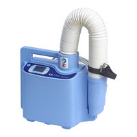
Covidien WarmTouch Service Manual (314 pages)
Convective Warming Unit
Brand:
Covidien
| Category:
Medical Equipment
| Size: 9.65 MB
Table of Contents
Table of Contents
3
Introduction
15
Overview
15
Safety Information
16
Safety Symbol Definitions
16
Warnings (Service)
16
Cautions (Service)
17
Warnings (Patient Treatment)
18
Cautions (Patient Treatment)
20
ESD (Electrostatic Discharge) Precautions
21
Tools Required for Service
21
Serial Number, Software Version, and Error Codes
23
Figure 1-1 Serial Number Label on Back of Warming Unit
23
Figure 1-2 Menu Screen
24
Figure 1-3 System Information Screen
24
Component Disposal - WEEE Directive
25
Labeling Symbols
26
Introduction
26
Obtaining Technical Assistance
28
Related Documents
31
Warranty Information
31
Product Overview
33
Overview
33
Product Description
33
Features
33
Indications for Use
34
Contraindications
34
Covidien Warmtouch™ Warming Blankets
34
Product Views
35
Front View
35
Figure 2-1 Front View
35
Back View
36
Product Overview
36
Figure 2-2 Back View
36
Operator's Panel
37
Figure 2-3 Operator's Panel
37
Installation
39
Overview
39
Safety Reminders
39
Attaching the Power Cord
40
Figure 3-1 Positioning the Unit for Power Cord Installation
40
Figure 3-2 Power Cord Connection
41
Figure 3-3 Power Cord Wrapped and Secured
42
Installing the Warming Unit
43
Pole Installation
43
Figure 3-4 Back View
44
Figure 3-5 Warming Unit Mounted on IV Pole
45
Bed Installation
46
Figure 3-6 Bed Installation
46
Cart Installation
47
Figure 3-7 Back View
47
Figure 3-8 Cart Mounting Peg and Warming Unit Mounting Hole
48
Figure 3-9 Warming Unit Mounted on Cart
49
Operation
51
Overview
51
Safety Reminder
51
Applying Power
52
Overview of Warming Unit Operating Modes
53
Beginning Operation
54
Figure 4-1 Main Screen at Power-On
54
Figure 4-2 Replace Filter Screen at Power-On
54
Controlling the Temperature
55
Using Boost Mode
56
Figure 4-3 Warming System Set to 40°C (Medium)
56
Figure 4-4 Warming System Set to Boost Mode
56
Using the Heat off Setting
57
Returning to Ready Mode
57
Figure 4-5 Warming System Set to Heat off
57
Figure 4-6 Warming System Set to Ready Mode
57
Returning to Standby Mode
58
If Power Is Interrupted
58
Powering off the Warming Unit
58
Maintenance
59
Overview
59
Safety Reminders
59
Cleaning the Warming Unit
60
Safety Checks
61
Physical Inspection
61
Temperature and Alarm Verification
61
Electrical Safety Tests
61
Filter Replacement
62
Figure 5-1 Replace Filter Screen
62
Figure 5-2 Filter Enclosure and Power Cord Connection
63
Figure 5-3 HEPA Filter
64
Figure 5-4 Gasket Inside Filter Enclosure
65
Figure 5-6 Filter Information Screen - Filter Expired
66
Figure 5-7 Main Screen at Power-On
67
Figure 5-8 Power Cord Wrapped and Secured
67
Monitoring the Filter Status
68
Figure 5-9 Menu Screen
68
Figure 5-10 Filter Information Screen
69
Troubleshooting
71
Overview
71
Safety Reminders
71
Principles of Operation
72
Overview
72
Block Diagram
73
Figure 6-1 Warming Unit Block Diagram
73
Component Descriptions
74
Component Cable Connections
78
Figure 6-2 Cable Connections between Major Components
78
Basic Troubleshooting
79
Figure 11-1 Thermistor Sensor Assembly
81
Figure 11-8 Thermostat
81
Figure 11-13 Thermostat Cable
81
Alarms
82
Figure 6-3 Low-Priority Alarm (Left) and Medium-Priority Alarm (Right)
82
Performance Verification
85
Overview
85
Safety Reminders
85
Required Test Equipment
86
Service Screen Access
86
Figure 7-1 Key Code Screen
86
Performance Tests
87
Power-On Test
87
Figure 7-2 Main Screen at Power-On
88
Figure 7-3 Replace Filter Screen at Power-On
88
Keypad Test
89
Display Test
91
Temperature Accuracy Test
92
Figure 7-4 Position of Hose for Temperature Accuracy Test
92
Flow Test
94
Figure 7-5 Position of Hose for Flow Test
94
Thermostat Test
95
Figure 7-6 Menu Screen
95
Figure 7-7 Key Code Screen
95
Figure 7-8 Select Test Screen
96
Figure 7-9 Thermostat Test Screen
96
Electrical Safety Tests
98
Ground Bond Test
98
Earth Leakage Current Test (Line Leakage)
98
Enclosure Leakage Current Test (Line Leakage)
98
External Component Replacement
99
Overview
99
Safety Reminders
99
Pole Clamp Replacement
100
Figure 8-1 Pole Clamps
100
Figure 8-2 Pole Clamp Foot and Knob
101
USB Port Cover Replacement
102
Figure 8-3 USB Port Cover
102
Power Cord Replacement
103
Figure 8-4 Power Cord Connection
103
Figure 8-5 Power Cord Wrapped and Secured
105
Nozzle Replacement
106
Figure 8-6 Nozzle
106
Figure 8-7 Nozzle Clips
107
Nozzle Strap with Clip Replacement
108
Figure 8-8 Nozzle Strap with Clip
108
No Free-Hosing Label Replacement
109
Figure 8-9 no Free-Hosing Labels on Front Enclosure (L) and Nozzle (R)
109
Accessing the Inside of the Warming Unit
111
Overview
111
Safety Reminders
111
Separating the Front and Rear Enclosures
112
Figure 9-1 Separated Enclosures
112
Figure 9-2 Power Cord Connection
113
Figure 9-3 Enclosure Screws
114
Rejoining the Front and Rear Enclosures
115
Figure 9-4 Rejoining the Enclosures
115
Figure 9-5 Power Cord Connection
116
Figure 9-6 Power Cord Wrapped and Secured
117
Figure 10-15 Ribbon Cable
119
Figure 10-27 Speaker
119
Internal Component Replacement (Inside Front Enclosure)
120
Safety Reminders
120
Keypad Replacement
121
Figure 10-1 Keypad
121
Figure 10-2 Keypad Cable Connection on UI PCBA
122
Figure 10-3 Removing the Keypad
123
Figure 10-4 Feeding the Keypad Cable through the Access Slot
124
Figure 10-5 Aligning the Keypad
124
Figure 10-6 Keypad Cable Secured by Locking Bar
125
Display (LCD) Replacement
126
Figure 10-7 Display Behind UI PCBA
126
Figure 10-8 Display Cable Connection on UI PCBA
127
Figure 10-9 Positioning the Display
128
User Interface (UI) PCBA Replacement
130
Figure 10-10 UI PCBA
130
Figure 10-11 UI PCBA Connections
132
Figure 10-12 USB Connection on UI PCBA
133
Figure 10-13 Attaching Backing Plate and Cable Tie to UI PCBA
134
Figure 10-14 Keypad Cable Secured by Locking Bar
136
Ribbon Cable Replacement
137
Figure 10-16 Ribbon Cable Connections
138
USB Cable Replacement
140
Figure 10-17 USB Cable
140
Figure 10-18 USB Port
141
Figure 10-19 UI PCBA Connections
142
Figure 10-20 USB Connection on UI PCBA
143
Figure 10-21 Attaching Backing Plate and Cable Tie to UI PCBA
144
Figure 10-22 Keypad Cable Secured by Locking Bar
146
Clock Battery Replacement
147
Figure 10-23 Clock Battery on UI PCBA
147
Power PCBA Replacement
149
Figure 10-24 Power PCBA
149
Figure 10-25 Power PCBA Connections
151
Fuse Replacement
153
Figure 10-26 Fuses on Power PCBA
153
Speaker Replacement
155
Figure 10-28 Speaker Cable Connections
156
Speaker Cable Replacement
158
Figure 10-29 Speaker Cable
158
Figure 10-30 Speaker Cable Connections
159
Power Supply Replacement
161
Figure 10-31 Power Supply
161
Figure 10-32 Power Supply Connections
162
Power Supply Output Cable Replacement
164
Figure 10-33 Power Supply Output Cable
164
Figure 10-34 Power Supply Output Cable Connections
165
Ground Cable Replacement
166
Figure 10-35 Ground Cable
166
Figure 10-36 Ground Cable Terminal on Equipotential Stud
167
AC Power Inlet Replacement
169
Figure 10-37 AC Power Inlet
169
Figure 10-38 AC Power Inlet Connections
170
Figure 10-39 Equipotential Stud Connections
171
Equipotential Stud Replacement
173
Figure 10-40 Equipotential Stud
173
Figure 10-41 Equipotential Stud Connections
174
Figure 10-42 Equipotential Stud and Washer
175
Internal Component Replacement (Inside Rear Enclosure)
178
Safety Reminders
178
Thermistor Sensor Assembly Replacement
179
Figure 11-2 Thermistor Wire and Rivet
180
Figure 11-3 Thermistor Cable Connections
181
Figure 11-4 Attaching Rivet to Thermistor Wire
182
Figure 11-5 Inserting Thermistor Wire and Rivet
182
Figure 11-6 Thermistor Position Inside Hose Duct Adapter
183
Figure 11-7 Inserting the Hose Duct Adapter
183
Thermostat Replacement
185
Figure 11-9 Thermostat Cable Connection to Thermostat
186
Figure 11-10 Thermostat Rivets (Outside of Hose Duct Adapter)
187
Figure 11-11 Thermostat Rivets (Inside of Hose Duct Adapter)
188
Figure 11-12 Inserting the Hose Duct Adapter
188
Thermostat Cable Replacement
190
Figure 11-14 Thermostat Cable Connection to Power PCBA
191
Figure 11-15 Thermostat Cable Connection to Thermostat
192
Pole Clamp and Mounting Bolt Replacement
194
Figure 11-16 Pole Clamps
194
Figure 11-17 Pole Clamp Foot and Knob
195
Figure 11-18 Pole Clamp Mounting Bolt
196
Hose Replacement
197
Figure 11-19 Hose
197
Figure 11-20 Wire Attaching Hose to Hose Duct Adapter
198
Figure 11-21 Inserting Hose Duct Adapter
199
Hose Duct Adapter Replacement
201
Figure 11-22 Hose Duct Adapter
201
Figure 11-23 Thermistor Wire and Rivet
202
Figure 11-24 Thermostat Cable Connection to Thermostat
203
Figure 11-25 Wire Attaching Hose to Hose Duct Adapter
204
Figure 11-26 Thermostat Rivets (Outside of Hose Duct Adapter)
205
Figure 11-27 Thermostat Rivets (Inside of Hose Duct Adapter)
206
Figure 11-28 Inserting the Hose Duct Adapter
207
Figure 11-29 Inserting Thermistor Wire and Rivet
208
Fan Assembly Replacement
209
Figure 11-30 Fan Assembly
209
Figure 11-31 USB Port
210
Figure 11-32 Filter Enclosure and Screws
211
Figure 11-33 Power PCBA Connections
212
Figure 11-34 Fan Assembly Screws
213
Figure 11-35 Cable Tie Securing Fan Cable to Thermistor Cable
214
Figure 11-36 Position of Fan Assembly
215
Figure 11-37 Inserting the Hose Duct Adapter
216
Figure 11-38 Securing the Hose Duct Adapter
216
Figure 11-39 USB Connector in Rear Enclosure
217
Heater Assembly Replacement
219
Figure 11-40 Heater Assembly (below Fan Assembly)
219
Figure 11-41 USB Port
220
Figure 11-42 Filter Enclosure and Screws
221
Figure 11-43 Power PCBA Connections
222
Figure 11-44 Fan Assembly Screws
223
Figure 11-45 Fan Assembly and Hose Duct Adapter
224
Figure 11-46 Fan Assembly Pulled for Heater Replacement
225
Figure 11-47 Heater Assembly and Gasket
226
Figure 11-48 Routing of Heater Wires
227
Figure 11-49 Inserting the Hose Duct Adapter
228
Figure 11-50 Securing the Hose Duct Adapter
228
Figure 11-51 USB Connector in Rear Enclosure
229
Figure 11-52 Routing of Cables Around Fan Assembly
230
12 Enclosure Replacement
233
Overview
233
Safety Reminders
233
Front Enclosure Replacement
234
Figure 12-1 Front Enclosure - Components to be Removed/Reinstalled
234
Figure 12-2 Equipotential Stud Connections
235
Figure 12-3 AC Power Inlet Connections
236
Figure 12-4 Power Supply Connections
237
Figure 12-5 Speaker Connections
238
Figure 12-6 Power PCBA Connections
239
Figure 12-7 UI PCBA Connections
240
Figure 12-8 Keypad Cable Secured by Locking Bar
241
Filter Enclosure Replacement
244
Figure 12-9 Filter Enclosure
244
Figure 12-10 Power Cord Wrapped and Secured
246
Rear Enclosure Replacement
247
Figure 12-11 Rear Enclosure (Outside) - Components to be
247
Figure 12-12 Rear Enclosure (Inside) - Components to be
248
Figure 12-13 USB Connector and Screws
250
Figure 12-14 Filter Enclosure and Power Cord Connection
251
Figure 12-15 Power PCBA Connections
252
Figure 12-16 Cable Ties to be Removed from Rear Enclosure
253
Figure 12-17 Fan Assembly Screws
254
Figure 12-18 Heater Assembly and Gasket
255
Figure 12-19 Pole Clamps and Mounting Bolts
256
Figure 12-20 Serial Number Label
257
Figure 12-21 Cable Tie Mount for Thermistor Cable
257
Figure 12-22 Position of Heater Cone and Screen
258
Figure 12-23 Routing of Heater Wires
259
Figure 12-24 Position of Hose Duct Adapter
260
Figure 12-25 Inserting the Hose Duct Adapter
261
Figure 12-26 Securing the Hose Duct Adapter
261
Figure 12-27 USB Connector in Rear Enclosure
262
Figure 12-28 Thermistor Cable Secured
263
Figure 12-29 Cable Ties and Routing of Cables
264
Figure 12-30 Serial Number Label
265
13 Product Specifications
267
Overview
267
Physical Characteristics
267
Warming Unit
267
Transport Cart (Optional)
267
Electrical Requirements
268
Environmental Specifications
268
Operating
268
Shipping and Storage
268
Performance Specifications
269
Product Compliance
269
Electromagnetic Compatibility (EMC)
270
Manufacturer's Declaration
270
Electromagnetic Emissions
270
Electromagnetic Immunity
271
14 Packing for Shipment
275
Overview
275
Returning the Warming Unit to Covidien
275
Packing in the Original Carton
276
Figure 14-1 Packing in the Original Carton
277
Packing in a Different Carton
278
A Parts and Accessories
279
Overview
279
External Components
280
Internal Components (Inside Front Enclosure
281
Internal Components (Inside Front Enclosure)
281
Internal Components (Inside Rear Enclosure
283
Internal Components (Inside Rear Enclosure)
283
Enclosures
284
Miscellaneous Components
285
Parts Locator
286
Figure A-1 External Components (Front
286
Figure A-2 External Components (Back
287
Parts Locator
287
Figure A-3 External Components (Bottom
288
Figure A-4 HEPA Filter (Filter Enclosure Removed
288
Figure A-5 Internal Components (Inside Front Enclosure
289
Figure A-6 Internal Components (Inside Rear Enclosure
290
B Error Codes
291
Overview
291
Error Codes and Suggested Resolutions
292
C Service Test Data Sheet
307
Overview
307
Index
309
Advertisement
Advertisement
Related Products
Covidien DAR
Covidien Endo Stitch
Covidien Force FX
Covidien Force FX-C
Covidien ForceTriad
Covidien HawkOne H1-LS-INT
Covidien HawkOne H1-LX-INT
Covidien HawkOne LS
Covidien HawkOne LX
Covidien Categories
Medical Equipment
Accessories
Thermometer
Water Pump
Measuring Instruments
More Covidien Manuals
Login
Sign In
OR
Sign in with Facebook
Sign in with Google
Upload manual
Upload from disk
Upload from URL