Table of Contents
Advertisement
Quick Links
Advertisement
Table of Contents

Subscribe to Our Youtube Channel
Related Manuals for Okolab H301-PRIOR-NZ100-H117


Summary of Contents for Okolab H301-PRIOR-NZ100-H117
- Page 1 User Manual H301-PRIOR-NZ100-H117 REV 02 H301-PRIOR-NZ100-H117 Compatible with the following Z piezo stages Compatible with the following Okolab Controllers • • Prior: Prior NZ100; NZ 200 in H117 H301-T-BL-PLUS • UNO-COMBINED-CONTROLLER • H401-T-DUAL www.oko-lab.com...
- Page 2 User Manual H301-PRIOR-NZ100-H117 REV 02 Index Components and dimensions....................3 Insertion of the Sample Feedback Temperature Sensor ..............4 Working with 35 Petri Dish- ....................4 Working with 1”x3’’ and 1”x2’’chamber slides ................5 Connection of the Gas Supply ....................6 Working with Perfusion ......................
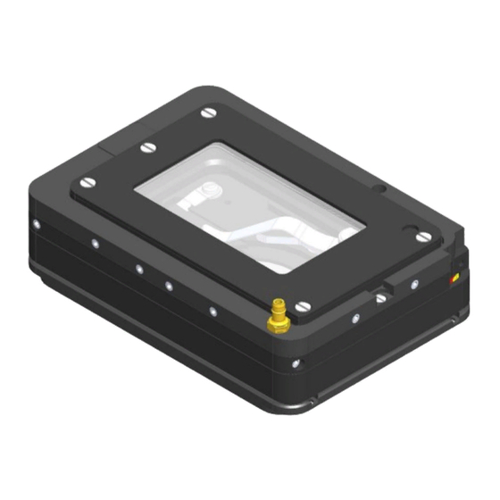
- Page 3 User Manual H301-PRIOR-NZ100-H117 REV 02 1. Components and dimensions H301-PRIOR-NZ100-H117 includes the following components: • Chamber main body with embedded temperature sensor • Heated glass Lid with Indium Tin Oxide (ITO) conductive coating and embedded temperature sensor • Chamber riser. It is a removable frame increasing the height of the chamber from 23 to 28 mm...
- Page 4 User Manual H301-PRIOR-NZ100-H117 REV 02 2. Insertion of the Sample Feedback Temperature Sensor Insert the Sample Feedback Temperature Sensor through one of 12 perfusion holes (see par 6. Figure 7) located in the H301-PRIOR-NZ100-H107 chamber riser (see Figure 2, Frontal and 3D views). Small screws plug the perfusion holes when not in use.
- Page 5 User Manual H301-PRIOR-NZ100-H117 REV 02 4. Working with 1”x3’’ and 1”x2’’chamber slides Flat springs prevent movement of 1”x3’’ and 1”x2’’ chamber slides inside of the sample holder. Figure 4. Sample holder for1”x3” chambered cover glass holder. Figure 5. 1 Sample holder for 1”x2” chambered cover glass holder.
- Page 6 A single silicon tubing carries output gas from the Okolab Gas Controller to the H301-PRIOR-NZ100-H117. Silicon tubing connects to a gas input - brass opening - located on a corner of the H301-PRIOR-NZ100-H117. See Figure 6. Connect by gently pushing silicon tubing onto brass opening.
- Page 7 User Manual H301-PRIOR-NZ100-H117 REV 02 7. Connection of the Chamber with Z Piezo Stage Follow the steps shown in the images of Figure 8 and listed below in order to correctly connect the chamber with Z piezo stage: Place the sample holder on the stage and tighten the four M2x3 Pan head screws, as shown in Figure 8 Image 1...
- Page 8 User Manual H301-PRIOR-NZ100-H117 REV 02 8. Cleaning • Turn the system off and pull the mains plug out the socket • Remove the lid from the chamber main body, and keep it separate from the chamber main body while the chamber cools down.
Need help?
Do you have a question about the H301-PRIOR-NZ100-H117 and is the answer not in the manual?
Questions and answers