
Related Manuals for Tecfluid CU Series


Summary of Contents for Tecfluid CU Series
- Page 1 Instructions manual Series CU Ultrasonic flowmeter The art of measuring R-MI-CU100 Rev.: 2 English version...
- Page 2 PREFACE Thank you for choosing a product from Tecfluid S.A. This instruction manual allows installation, configuration, programming and maintenance. It is recommended to read it before using the equipment. WARNINGS • This document shall not be copied or disclosed in whole or in any part by any means, without the written permission of Tecfluid S.A.
-
Page 3: Table Of Contents
TABLE OF CONTENTS SERIES CU INTRODUCTION ................INSTALLATION OF THE ELECTRONIC CONVERTER ...... Electrical connection ............2.1.1 Power supply wiring ..........2.1.2 Relay output wiring ..........2.1.3 Analog output wiring ..........2.1.4 Transducers wiring ..........CONVERTER INTERFACE .............. MAIN MENU ................. Passwords to access the menus ......... - Page 4 5.15 Programs ................5.16 Transducers test ..............CONVERTER PROGRAMMING ............Language ................Units .................. Decimals ................Flow rate ................6.4.1 Cut off ..............6.4.2 Reversed flow rate ..........6.4.3 Damping ..............6.4.4 Offset ..............Outputs ................6.5.1 Relay 1 and relay 2 ..........6.5.2 Analog output ............
- Page 5 ASSOCIATED SOFTWARE WINSMETER CU ........11.1 USB cable connection and drivers installation ...... 11.2 Port connection ..............11.3 Access to installation and programming ....... 11.4 Datalogger ................. 11.5 Visualization ............... 11.6 Simulation ................TECHNICAL CHARACTERISTICS ..........SAFETY INSTRUCTIONS ............... 13.1 Certificate of conformity TR CU (EAC marking) .....
-
Page 6: Introduction
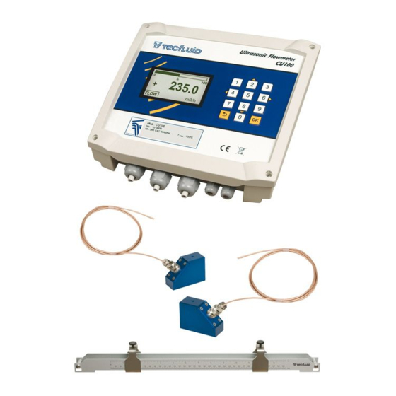
INTRODUCTION The CU100 flowmeter is an electronic device that is based on ultrasonic signal transmission through a pipe where a liquid is flowing. The working principle is called transit time. It consists of placing two ultrasound transducers on a pipe and sending an ultrasonic signal from the first to the second and back. -
Page 7: Electrical Connection
Electrical connection For the electrical connection, the CU100 converter has four terminal strips. To help in the wiring of the equipment, the description of the terminals is marked on the printed circuit next to each terminal strip. For the electrical installation it is recommended to use multiple conductor cables with individual cable sections in the order of 0.25 to 0.5 mm in order to make it easier to connect. -
Page 8: Power Supply Wiring
2.1.1 Power supply wiring Before starting the installation of the instrument, check that the supply voltage available is the same as marked on the label of the converter. Terminal Power supply Earth Neutral Phase It is important to connect the mains earth due to the presence of a mains filter inside that requires this connection. -
Page 9: Analog Output Wiring
The relay outputs are SPDT relays with potential free contacts (see characteristics in page 44). The state of the relay contacts corresponds to the relay at rest. The relay contacts are not protected in any way, and therefore the protections must be installed externally as required in the application, taking into account the limitations of the... -
Page 10: Transducers Wiring
The mA output is galvanically isolated. It can be active (which means that the receiver device connected to it should have a passive input) or passive (which means that the receiver device must provide the power supply for the current loop). It is recommended to use a receptor with an input resistance of less than 700 Ω... -
Page 11: Converter Interface
CONVERTER INTERFACE The CU100 converter has a graphic LCD and a keyboard with 12 push buttons. The keyboard has ten numeric keys to introduce the values of installation and programming. Two of these keys are used also as cursors, and finally there are two function keys. The following figure shows the functionality of the converter keys. -
Page 12: Main Menu
MAIN MENU To access the main menu of the converter, press the key (OK). The following screen appears: Number of menu items Selected item The "Installation" option allows the installation of the transducers, as explained in Chapter 5 of this manual. The "Programming"... - Page 13 When the "Password" option is selected, a screen to enter the new password appears. Once entered, the new password is asked again to avoid possible inadvertent error. the re-entered password does not match the first one, the following error message appears and the process should be carried out again.
-
Page 14: Transducers Installation
TRANSDUCERS INSTALLATION Make sure that the surface of the pipe where the transducers will be installed is clean and free of rust or other dirt. If possible, always install the transducers on a rising pipe, to ensure that it is always full of liquid. - Page 15 Disturbing element Minimum distance between the before first transducer and the element the transducers 90º elbow 90º double elbow in one plane 90º double elbow in different planes Reducer Diffuser Pump Valve...
- Page 16 Disturbing Minimum distance between the sec- element after ond transducer and the element the transducers 90º Elbow 90º double elbow in one plane 90º double elbow in different planes Diffuser Reducer Valve...
-
Page 17: Installation With The Alignment Guide
Installation with the alignment guide convenient to use the alignment guide (normally supplied for pipes from DN80 to DN350), to guarantee that the transducers are perfectly aligned. In case that the guide is not required or it is not supplied, the transducers can be installed directly with the supplied straps (see page 24). -
Page 18: Installation Parameters
In order to access to the transducers installation menu, a password must be entered. When accessing the first time, the default password is 0123. For more details about the password, see paragraph 4.1, page 12. Once the password is entered, and after pressing the key (OK), the first shown screen allows to choose between the different options of the installation menu. -
Page 19: Units
Units User can choose between metric and imperial units. Pipe parameters It is necessary to know some data such as materials, thicknesses, etc., so that the flowmeter can perform the necessary calculations to obtain the flow rate accurately. First, the outer diameter of the pipe must be entered. 5.8.1 Outer diameter The outer diameter value must always be entered in millimetres. -
Page 20: Pipe Material
5.8.2 Pipe material For the programming of the CU100 ultrasonic flowmeter, a list with several common pipe materials is available. For each material the flowmeter has the necessary data to perform a good measurement. In the event that the pipe material is not on the list, you must select “Another material”, in the last position in the list. -
Page 21: Lining Thickness
5.8.5 Lining thickness If the pipe has an internal lining, its thickness should be entered, in the same way as in the pipe thickness. Liquid The liquid that flows through the pipe should be selected. If the liquid is not in the list, “Another liquid” must be selected. In this case, it is necessary to enter the sound propagation velocity of the liquid. -
Page 22: Paths
5.10 Paths The number of paths is given by the transducer installation method. With the current available transducers, W mode will not be used. For pipe diameters up to 350 mm, V mode is recommended. This mode ensures that the propagation path of the ultrasonic wave is long enough so that the instrument can successfully perform the measurement. -
Page 23: Installation And Distance Between The Transducers
5.11 Installation and distance between the transducers This screen shows the theoretical distance (Dt) at which the transducers should be placed to work in the best conditions. The practical distance (Dr) is explained in the paragraph 5.14. To place the transducers it is essential to apply a layer of ultrasound gel at its base. This gel is supplied with the equipment. - Page 24 After placing the transducer, move the fastening "U" to it until the knurled screw matches the transducer top notch. Once in this position, tighten the screw until the transducer is pressed against the pipe. If the alignment guide is not available, place the strap around the pipe and tighten it so that it holds the transducer.
-
Page 25: Signal Strength
5.13 Signal strength This screen allows to perform a fine adjustment of the position of the second transducer. To do so, the second transducer must be moved to find the point where the signal level indicated on the display is maximum. From 30% it can be considered in most cases that the signal is adequate. -
Page 26: Transducers Test
5.16 Transducers test Through this screen a test of the transducers can be performed. This test allows to verify that they are in good condition. To do the test, put some gel on the transducers and face each other. The display should indicate a value between 90% and 100%. If not, please contact the manufacturer. -
Page 27: Language
Once the password is entered, the first screen allows to choose between the different programming options. Language You can choose the language in which all the menus will be displayed. Units In this screen the units for the liquid velocity, the flow rate and the totalizer can be chosen independently. -
Page 28: Decimals
Decimals In this screen the number of decimals for the flow rate indication can be selected. To select the number of decimals it must be taken into account that the instrument has 5 digits for flow rate indication. If two decimals have been selected, these will be seen whilst the flow rate is not higher than 999.99. -
Page 29: Damping
6.4.3 Damping The CU100 flowmeter has an adaptive filter (damping) to provide stable flow rate and analog output readings in the presence of continuous flow rate fluctuations. The configuration of this filter can be very useful in the cases where the flow rate readings have some instability (due to air bubbles, solids in suspension, etc.). - Page 30 When the read flow rate is stable, press the key OK and the instrument will save the value. If in the installation is not possible to stop the flow rate, an offset adjustment can be done if the flow rate is stable. To do this, press the option “Flow rate ≠...
-
Page 31: Outputs
Once a key is pressed, the offset will be adjusted. Outputs This screen allows to program the three outputs of the instrument: Relay 1, Relay 2 and analog output (4-20 mA). 6.5.1 Relay 1 and relay 2 When selecting one of these screens we have access to program the flow rate at which the relays will change its state and to the level of hysteresis. -
Page 32: Configuration Of The 4-20 Ma Output
6.5.3 Configuration of the 4-20 mA output It allows to choose between unidirectional and bidirectional. If “Unidirectional” is chosen, the analog output will have a value proportional to the flow rate when positive, and it will provide always 4 mA when negative. If “Bidirectional”... -
Page 33: Default Screen
Before doing a current calibration, be sure that the ammeter used for that is showing the real measure. Default screen Flow rate, totalizer or liquid velocity screens can be programmed as a default. Thus, the converter presents this screen when a power failure occurs or when returning from the installation or programming menu. -
Page 34: Backlight
Installation in which for a time the product flows through the pipe to a tank, and after that a quantity of the product comes back in the opposite direction. The programming will be: Positive flow rate action: Increase Negative flow rate action: Decrease The totalizer will indicate the volume of product that there is in the tank. -
Page 35: Serial Number
SERIAL NUMBER In this section the converter serial number is shown. DEFAULT SCREEN When exiting the menu, the display shows the default screen. To scroll between the three operating screens, press the key (2) or (8). If the device detects no signal at the transducers, because the attenuation is very high, or due to a bad connection or broken cable, the operating display appears as an informative screen indicating this situation MAINTENANCE... -
Page 36: Associated Software Winsmeter Cu
ASSOCIATED SOFTWARE WINSMETER CU Most of the steps in the preceding paragraphs can be done by means of the device associated software Winsmeter CU, which allows working in a more comfortable and intuitive way. Such software can be downloaded from the following link of the Tecfluid S.A. website. www.tecfluid.com/downloads/winsmeterCU.zip. - Page 37 To open the lid, remove the four screws. The USB connector is located on the opposite side of the cable entry glands. Connect the USB cable at one end to the converter and at the other to the computer where the software is installed.
-
Page 38: Port Connection
11.2 Port connection In the "Port" section, choose the appropriate port for the converter. This will appear with the name of the port followed by CU100 and its serial number. Then click "Open". Once the port is open, the button "Open" in the "Installation" section activates. 11.3 Access to installation and programming In order to access the tab "Install", you must enter a password. - Page 39 Once the password is written, press "Enter" or the corresponding "Open", and the installation or programming tab will open as appropriate. At the bottom of each section displays "Installation tab open" or "Programming tab open." To enter the Installation window, just click the appropriate tab.
- Page 40 Changing settings on this screen, you get the distance between the transducers on the bottom. To transfer data to the CU100 converter, press the “Send” button. The message "Saving program" will appear for two seconds in the converter screen. The installation data will be stored in the memory of the converter.
-
Page 41: Datalogger
11.4 Datalogger In this window the process of the different variables of the equipment can be registered in a file. The time between samples, as well as the start and end time of the record can be selected. When the "Register" button is pressed, the screen that allows to name the file and select its location appears. - Page 42 The created file has CSV format, which can be viewed directly with a spreadsheet.
-
Page 43: Visualization
11.5 Visualization When the communication with the computer port is established (see section 11.2), the tab "Visualization" opens. This tab lets you view real-time flow rate, totalizer and velocity values, as well as the current value of the analog output and the state of the relay outputs. It is an intuitive tool to verify that the instrument has been installed and programmed correctly. -
Page 44: Technical Characteristics
TECHNICAL CHARACTERISTICS Accuracy ± 1.5% of reading ± 0.02 m/s Repeatability ± 0.25% of reading ± 0.01 m/s Velocity range 0.2 ...12 m/s Connections External mounting in pipes of diameter between DN80 ... DN2000 Optional installation by means of guide or transducer straps Temperature Process temperature: -20ºC …... -
Page 45: Safety Instructions
SAFETY INSTRUCTIONS The series CU100 flowmeters are in conformity with all essential requirements of all EC directives applicable to them: 2014/68/EU Pressure equipment directive (PED) 2014/30/EU Electromagnetic compatibility directive (EMC) 2012/19/EU Waste electric and electronic equipment (WEEE). 2011/65/EU Restriction of the use of certain hazardous sub- stances in electrical and electronic equipment (ROHS). -
Page 46: Dimensions
DIMENSIONS... -
Page 48: Troubleshooting
TROUBLESHOOTING Problem Probable cause Solution Make sure that the pipe is completely The pipe is not completely full, for example, installing the flowmeter full. in a vertical pipe with upwards flow. Enter the installation menu and verify The transducers are not at that all parameters are correct. -
Page 49: Annex A Sound Propagation Velocity In Some Liquids
ANNEX A. Sound propagation velocity in some liquids (in m/s). Water Liquids 0 ºC 1190 1403 Acetone 1207 10 ºC Alcohol 1447 1386 20 ºC Ammonia 1482 1649 Aniline 30 ºC 1507 1482 Beer 40 ºC 1526 1320 Benzene 50 ºC 1541 Chloroform 60 ºC... -
Page 50: Annex B Sound Propagation Velocity In Some Solids
ANNEX B. Sound propagation velocity in some solids (in m/s). Pipe material Lining material Aluminium Bitumen 3080 2500 Brass Fiberglass 2150 3430 Bronze Glass 2270 3300 Cast iron 2550 1950 Copper Plastic 2260 2100 Ductile cast iron 2650 Porcelain 2540 Glass 3300 PTFE... -
Page 51: Annex C Flow Rate Table
ANNEX C. - Page 52 WARRANTY Tecfluid S.A. guarantee all the products for a period of 24 months from their sale, against all faulty materials, manufacturing or performance. This warranty does not cover failures which might be imputed to misuse, use in an application different to that specified in the order, the result of service or modification carried out by personnel not authorized by Tecfluid S.A., wrong handling or accident.
Need help?
Do you have a question about the CU Series and is the answer not in the manual?
Questions and answers