
Subscribe to Our Youtube Channel
Related Manuals for Tecfluid Series LT


Summary of Contents for Tecfluid Series LT
- Page 1 Instructions manual Series LT Level gauge The art of measuring R-MI-LT Rev.: 3 english version...
- Page 2 PREFACE Thank you for choosing a product from Tecfluid S.A. This instruction manual allows installation, configuration, programming and maintenance. It is recommended to read it before using the equipment. WARNINGS This document shall not be copied or disclosed in whole or in any part by any means, without the written permission of Tecfluid S.A.
-
Page 3: Table Of Contents
TABLE OF CONTENTS SERIES LT INTRODUCTION ................WORKING PRINCIPLE ..............MODELS ..................RECEPTION ................. HANDLING ................... INSTALLATION ................Minimum distances ............. LEVEL ASSEMBLY IN TWO SECTIONS .......... Model LT106 (stainless steel) ..........Model LT14 (plastic) ............LEVEL READING ................FLOAT TYPES ................ -
Page 4: Series Lt
14.4.1 Electrical connection ..........14.4.2 Mounting ............... 14.5 Compact transmitter ............LTDR TRANSMITTER ..............MAINTENANCE ................16.1 Series LT ................16.2 AMD limit switch maintenance ..........16.2.1 Electrical verification ..........16.3 AMM limit switch maintenance ..........16.4 APR limit switch maintenance .......... - Page 5 SAFETY INSTRUCTIONS ............... 18.1 Pressure equipment directive ..........18.2 Certificate of conformity TR CU (EAC marking) ..... ADDITIONAL INSTRUCTIONS FOR THE ATEX VERSION ....19.1 Flameproof enclosure ............19.1.1 Surface temperature ..........19.1.2 Connecting conductive parts to earth ....... 19.1.3 Maintenance ............19.1.4 Technical characteristics of the ATEX version ..
-
Page 6: Introduction
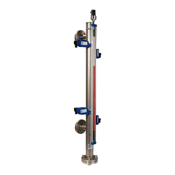
INTRODUCTION The level gauges series LT are very robust equipment and resistant to extreme conditions of temperature and pressure, as well as corrosive chemicals, depending on the manufacturing materials used. They can fit switches that allow to detect a specific level and provide an alarm signal to a remote device. -
Page 7: Reception
RECEPTION The series LT level gauges are supplied conveniently packaged for their protection during transportation and storage, together with their instructions manual for installation and operation. All the instruments have been verified in our facilities, ready for installation and operation. -
Page 8: Minimum Distances
Distance LMS between the lowest side of the level gauge and the floor must be kept longer or equal to LD distance. On the other hand, the lower dimension LD, LP or LPV of series LT level gauges is variable depending on the working liquid density. The lower the density, the longer the dimension. - Page 9 For the LT level gauges, once the level is connected to the tank, fill the glass tube, and next reassemble the glass tube on the chamber. This process should be done in the following way: Remove the M8 upper allen screw (1). Withdraw the glass tube from its support and remove the plug at the top (3).
-
Page 10: Level Assembly In Two Sections
LEVEL ASSEMBLY IN TWO SECTIONS When the level gauge is delivered in two sections, due to its total length, the following instructions must be followed carefully for its correct installation. The numbering of the different elements corresponds to the different figures. NOTE: Handle the glass tube sections with care. - Page 11 Check the placement of the NBR gasket Ø63 x 3 (15) in its seat on top of the lower flange (7) and the NBR gasket Ø31.42 x 2.62 (16) on top of the lower glass tube (5). Place the upper half of the level gauge above the lower half and in the coaxial position, and carefully go down by passing the upper glass tube (14) through the corresponding hole in the lower flange (7) until the upper flange (9) rests on the NBR gasket Ø63 x 3 (15).
- Page 12 Join the two halves of the level by means of the 4 screws DIN933, variable metric according to model (18), and their corresponding washers and nuts, and fix the level to the upper connection of the installation. Slightly loosen the clamp (11) that fixes the upper support (12), remove the adhesive tape from the upper glass tube (14) and lower it until it rests on the seal (16).
- Page 13 Remove the screw (19) and the plug (20) and proceed to fill the glass tube (14+5). Re-insert the plug (20) into the tube (14) and, keeping the upper support (12) slightly pressed down, tighten the clamp (11) and the screw (19).
-
Page 14: Model Lt14 (Plastic)
Model LT14 (plastic) Fix the lower half of the level gauge to the installation. The mobile flange-group (1) allows adjusting its anchoring height. Remove the adhesive tape from the lower glass tube (6) and loosen the 3 screws DIN933 M5 x 30 (5) without removing the nuts (3). In case there is not enough space to introduce the float (7) through the lower part of the gauge body once the assembly has been completed, the float must be in its correct position inside this lower half at the time of installation. - Page 15 Check the placement of the NBR gasket Ø63 x 3 (16) in its seat on top of the lower flange (8), and the NBR gasket Ø31.42 x 2.62 (17) on top of the lower glass tube (6). Place the upper half of the level gauge above the lower half and in the coaxial position, and carefully go down by passing the upper glass tube (15) through the corresponding hole in the lower flange (8) until the upper flange (10) rests on the NBR Ø63 x 3 gasket (16).
- Page 16 Join the two halves of the level gauge by means of the 4 screws DIN933, variable metric according to model (19), and their corresponding washers and nuts, and fix the level gauge to the upper connection of the installation. Slightly loosen the clamp (12) that fixes the upper support (13), remove the adhesive tape from the upper glass tube (15) and lower it until it rests on the seal (17).
- Page 17 Remove the screw (20) and the plug (21) and proceed to fill the glass tube (15+6). Re-insert the plug (21) into the tube (15) and, keeping the upper support (13) slightly pressed down, tighten the clamp (12) and the screw (20).
-
Page 18: Level Reading
LEVEL READING For level gauges with a glass tube (LT models), the value of the level is read on the scale at the height of the top of the external follower. For level gauges with indication by means of magnetic strips (LTL models), the reading is taken where the strips change from red to white. -
Page 19: Amd Limit Switch
AMD LIMIT SWITCH 10.1 Introduction The AMD limit switch can be used to generate an alarm or an operation when the level that the instrument is measuring reaches a preset value. It is a bi-stable limit switch. It consists of a NAMUR slot type inductive sensor, that is actuated by the float, by means of a vane that changes its position from one detection position to the other. -
Page 20: Ltl Models
10.3.2 LTL models To fix the limit switch on the level gauge, loosen the nuts (D), move the switch to the desired height and tighten the nuts (D) again. The position of the reading point of the float with respect to the switching point of the limit switch can vary from one type of float to another. -
Page 21: Mounting
10.5 Mounting Once the electrical connection is made and the cable gland is tightened, connect the female connector (A) to the male base (C) in the correct position, placing the gasket (B) between them. AMM LIMIT SWITCH 11.1 Introduction The AMM limit switch can be used to generate an alarm or an operation when the level that the instrument is measuring reaches a preset value. -
Page 22: Ltl Models
The position of the reading point of the float with respect to the switching point of the limit switch can vary from one type of float to another. If it is the first time that the switching point is adjusted, with the float in a stable position, move the limit switch until the micro-switch switches. -
Page 23: Electrical Connection
11.4 Electrical connection For the electrical installation it is recommended to use multiple conductor cables, and not single cables, in order to guarantee the cable gland will stay watertight. The connector has a PG9 cable gland for cables with outer diameters between 5 mm and 7 mm. The numbering of the terminals is the following: In the female connector (A): Terminal 1:... -
Page 24: Apr Limit Switch
APR LIMIT SWITCH 12.1 Introduction The APR limit switch can be used to generate an alarm or an operation when the level that the instrument is measuring reaches a preset value. It is a bi–stable SPDT limit switch. It consists of a reed sensor that is actuated by the magnetic field of the float. 12.2 Operation When the float passes through the point where the limit switch is positioned, it changes the... -
Page 25: Ltl Models
12.3.2 LTL models To fix the limit switch on the level gauge, loosen the nuts (D), move the switch to the desired height and tighten the nuts (D) again. The position of the reading point of the float with respect to the switching point of the limit switch can vary from one type of float to another. - Page 26 Make sure that the contact rating is not exceeded. If high loads are to be switched, use an auxiliary relay. When using inductive loads, such as relays or solenoid valve coils, surge arresters should be installed to protect the reed contacts. With a DC supply, a diode should be connected as shown.
-
Page 27: Aar Limit Switch
AAR LIMIT SWITCH 13.1 Introduction The AAR limit switch can be used to generate an alarm or an operation when the level that the instrument is measuring reaches a preset value. It is a bi–stable SPDT limit switch. t is used when the product can reach high temperatures (see characteristics on page 35), and is only available for glass tube indication system with external follower (LT models). -
Page 28: Electrical Connection
13.4 Electrical connection For the electrical installation it is recommended to use multiple conductor cables, and not single cables, in order to guarantee the cable gland will stay watertight. The connector has a PG9 cable gland for cables with outer diameters between 5 mm and 7 mm. The numbering of the terminals is the following: In the female connector: Terminal 1:... -
Page 29: Lte Transmitter
When installing the connector, make sure that the cable gland (A) closes over the cable and that the connector (B) with the rubber seal (C) is well screwed down to maintain the IP65 rating. LTE TRANSMITTER 14.1 Introduction The LTE transmitter is a resistive sensor based on the variation of resistance as a function of the height of the float. -
Page 30: Remote Transmitter
14.4 Remote transmitter When the transmitter is remote, the resistive system includes a connector DIN 43650A. 14.4.1 Electrical connection For the electrical installation it is recommended to use multiple conductor cables, and not single cables, in order to guarantee the cable gland will stay watertight. The connector has a PG9 cable gland for cables with outer diameters between 4.5 mm and 7 mm. -
Page 31: Compact Transmitter
14.5 Compact transmitter When the transmitter is compact, it can be supplied with plastic or aluminium housing. Transmitter in plastic housing Transmitter in aluminium housing Connection of these transmitters can be found in the transmitter specific instructions. -
Page 32: Ltdr Transmitter
TDR sensors are also known as guided radar devices. The information related to these transmitters can be found in its specific manual. MAINTENANCE 16.1 Series LT No special maintenance is required. 16.2 AMD limit switch maintenance 16.2.1 Electrical verification Check that the voltage at the terminals + and - is over 7.5 V when the vane is in the slot. -
Page 33: Amm Limit Switch Maintenance
With the potentiometer the current through the NAMUR amplifier can be modified. The switching point must be between 1.2 mA and 2.1 mA. That is, with the current below 1.2 mA the output relay must have a state and above 2.1 mA the output relay must have the other state. -
Page 34: Technical Characteristics
TECHNICAL CHARACTERISTICS 17.1 Series LT Accuracy ±10 mm measured value Liquid density 0,55 ... 2 kg/l (others on request) Liquid viscosity 1500 cSt maximum Measuring range 150 mm ... 15 m Temperature Liquid temperature: LTL106: -20ºC … 200ºC LT106: -20ºC … 400ºC, depending on configuration LT ... -
Page 35: Amm Limit Switch
17.3 AMM limit switch Aluminium housing DIN 43650 A connector Technical characteristics of the micro-switch: Maximum switching voltage: 250 VAC Maximum switching current: Hysteresis: ±10% of full scale value Ingress protection: IP65 Liquid temperature: -20ºC ... +250ºC Ambient temperature: -25ºC ... +80ºC 17.4 APR limit switch Polycarbonate housing... -
Page 36: Safety Instructions
18.1 Pressure equipment directive Tecfluid S.A. have subjected the series LT of level gauges to a conformity assessment method for the pressure equipment directive, specifically according to module H (full quality assurance). Conformity with the directive is reflected by the CE marking in each pressure equipment and by the written declaration of conformity. -
Page 37: Additional Instructions For The Atex Version
ADDITIONAL INSTRUCTIONS FOR THE ATEX VERSION This chapter only applies to equipment intended for use in explosive atmospheres. The equipment with AMM or AMR limit switches can be considered as simple apparatus according to the IEC 60079-11 standard, and thus they do not need to be marked as ATEX. The equipment with AMD limit switches can be installed in potentially explosive atmospheres as elements of intrinsic safety. -
Page 38: Maintenance
19.1.3 Maintenance NOTE: Before performing any maintenance that involves opening the flameproof enclosure, make sure that there is no tension in any of its internal components. Modification or reparation of the flameproof housing is not permitted. The flameproof seals of the housing should kept greased to avoid corrosion, water ingress and seizing. -
Page 39: Name Plate
NAME PLATE Each level gauge is delivered identified with its nameplate. The different parameters of the plate are the following: PV: Tecfluid’s order number DN and PN: Nominal diameter and Nominal pressure. These parameters determine the dimensions of the flanges, tubes, etc, according to each standard. They also serve to relate the maximum working pressure at a specific temperature. -
Page 40: Dimensions
DIMENSIONS LT … LTL106 Flanged connection Threaded connection All dimensions in mm... - Page 41 LT … LTL15 / PTFE LT … LTL14 / PP, PVC, PVC-C, PVDF All dimensions in mm...
- Page 42 LT-AMM / AMD LTL-AMM / AMD LT-APR LTL-APR All dimensions in mm...
- Page 43 LT-AAR LT-xxx ADF LTL-xxx ADF All dimensions in mm...
-
Page 44: Atex Certificate
ATEX CERTIFICATE... -
Page 46: Atex Declaration Of Conformity
ATEX DECLARATION OF CONFORMITY... - Page 48 WARRANTY Tecfluid S.A. guarantee all the products for a period of 24 months from their sale, against all faulty materials, manufacturing or performance. This warranty does not cover failures which might be imputed to misuse, use in an application different to that specified in the order, the result of service or modification carried out by personnel not authorized by Tecfluid S.A., wrong handling or accident.
Need help?
Do you have a question about the Series LT and is the answer not in the manual?
Questions and answers