
Subscribe to Our Youtube Channel
Related Manuals for Tecfluid M21 Series


Summary of Contents for Tecfluid M21 Series
- Page 1 Instructions manual Series M21 Variable area flowmeter The art of measuring R-MI-M21 Rev.: 4 English version...
- Page 2 PREFACE Thank you for choosing a product from Tecfluid S.A. This instruction manual allows installation, configuration, programming and maintenance. It is recommended to read it before using the equipment. WARNINGS • This document shall not be copied or disclosed in whole or in any part by any means, without the written permission of Tecfluid S.A.
-
Page 3: Table Of Contents
TABLE OF CONTENTS SERIES M21 INTRODUCTION ................WORKING PRINCIPLE ..............RECEPTION .................. INSTALLATION ................Valves ................Filters ................. Straight pipe sections ............OPERATION ................. Gas flow measurement ............Gas damping mechanism ............ Liquid flow measurement ............ RCA / RCD FLOW REGULATORS ..........Regulation curves ............... - Page 4 12.2 TH6H ................. ELECTRICAL CONNECTION ............13.1 Power supply and analog output ......... 4-WIRE CONNECTION ..............HART TRANSMITTERS ..............15.1 Additional functions with HART communication ....15.2 HART communication characteristics ........”WRITE PROTECT” ............... MAINTENANCE ................17.1 Series M21 ................ 17.2 M21 with damping system ..........
- Page 5 SAFETY INSTRUCTIONS ............... 19.1 Pressure equipment directive ..........19.2 Certificate of conformity TR CU (EAC marking) ..... ADDITIONAL INSTRUCTIONS FOR THE ATEX VERSION ....20.1 Non-metallic parts .............. 20.2 Connecting conductive parts to earth ........20.3 AMD limit switch ..............34 20.4 TH6 transmitters ..............
-
Page 6: Series M21
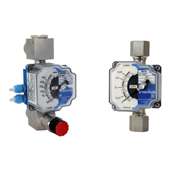
SERIES M21 INTRODUCTION The series M21 are flowmeters for liquids, gases and steam. They are very robust instruments prepared to work under extreme conditions. They have local flow rate indication by means of magnetic coupling, with scales calibrated in l/h, m /h, kg/h, t/h, %, etc. - Page 7 M21 models always work in a vertical position with upwards flow. The equilibrium point is determined by considering the fluid force and the float weight. The M21-H... models have horizontal inlet and outlet, and optionally they can be supplied with a regulating valve on the inlet.
-
Page 8: Reception
RECEPTION The series M21 flowmeters are supplied conveniently packaged for their protection during transportation and storage, together with their instructions manual for installation and operation. The instruments are supplied tested in our calibration rigs, ready for installation and service. Before installing the flowmeter, remove all the blocking elements. With the instrument in its working position, move the float and check that the indicating needle moves all over the scale and returns to zero. -
Page 9: Operation
OPERATION Once the meter is installed, the regulating valve should be opened slowly. The fluid flow will move the float which, by means of magnetic coupling, moves the indicating needle. Any variations of working conditions with respect to those when calibrated can induce reading errors. -
Page 10: Gas Damping Mechanism
If the regulation is done using the shut off valve, in open circuits or at low gas flow in the meter, the gas will expand which will sharply diminish its density, providing very serious reading errors. If the flow is regulated by the shut off valve, the float usually experiences an oscillating movement which produces a shut off action until sufficient pressure is gained to overcome its weight. -
Page 11: Liquid Flow Measurement
When measuring low pressure gas flow with AISI 316L floats, oscillation of the float often occurs, which makes it very difficult to read the flow rates. In these cases it is recommended to install a damper in the instrument. The damper consists of a piston mounted inside a cylinder, closed at its lower end. The compression forces of the gas absorb the floats oscillations, maintaining it stable in the reading point. -
Page 12: Rca / Rcd Flow Regulators
RCA / RCD FLOW REGULATORS The M21 series flowmeters are built to incorporate the RCA and RCD regulators, that keep a constant flow rate when the operating pressure at the inlet or outlet are not constant. In applications for gases, the RCA model is used in installations where inlet pressure is... -
Page 13: Regulation Curves
The differential pressure between P and P higher than 350-450 2 should always be mbar depending on the model. This differential pressure is calculated for the proper operation of the flow rate regulator. Regulation curves The flow curves show the relationship between the inlet pressure P and the counter pressure P... - Page 14 Q air (Nl/h) variation of flow (bar) P0 = inlet pressure RCA regulator (high flow) Q air (Nl/h) variation of flow (bar) P0 = outlet pressure RCD regulator (low flow)
-
Page 15: Amd Limit Switch
AMD LIMIT SWITCH INTRODUCTION The AMD limit switch can be used to generate an alarm or an operation when the flow rate that the instrument is measuring reaches a preset value on the scale plate. The AMD limit switch consists of a NAMUR slot type inductive sensor, that is actuated by a vane. -
Page 16: Mounting The Limit Switch In An Existing Equipment
MOUNTING THE LIMIT SWITCH IN AN EXISTING EQUIPMENT When the AMD limit switch is to be fitted to an existing device, please follow these steps. Kit contents The kit contains the following elements: AMD kit Quantity Material Position AMD limit switch circuit Self tapping screw DIN7982 B-2,2 x 9,5 Nº2 A2 AMD vane Self tapping screw DIN7982 B-2,2 x 9,5 Nº2 A2... -
Page 17: Assembling The Amd Kit
Assembling the AMD kit Slide the circuit (1) into the slot until it stops, and then screw it as shown in the figure. Slot Screw (2) Screw (2) Place the vane (3) in the position shown in the figure. The height on the shaft should be such that when the vane passes through the sensor slots, remains centered without touching them. -
Page 18: Switching Point Adjustment
Switching point adjustment At the bottom of the switching needle, the fixing nuts of the switching points can be found. To move the switching point, the fixing nuts have to be slightly loosen without removing the scale plate (see figure on the next page). After that, place the switching point at the required scale value, and fix it with the nuts. -
Page 19: Electrical Connection
Electrical connection Do it according to section 10. Mounting Slide the scale plate into the slot until it stops as shown in the figure. Mount the cover with the four screws M4. ELECTRICAL CONNECTION For the electrical connection, the instrument is provided with a four terminal connector. For the electrical installation it is recommended to use multiple conductor cables with sections of 0.25 or 0.5 mm , in order to make it easier to connect. -
Page 20: Th6 Transmitters
TH6 TRANSMITTERS INTRODUCTION Transmitters TH6 are electronic position transducers with a microprocessor. The instrument uses the Hall effect to capture the field of a magnet. This signal, after the microcontroller processing, is converted into a current signal of 4-20 mA in a 2-wire loop. This signal is proportional to the flow rate. -
Page 21: Power Supply And Analog Output
13.1 Power supply and analog output 12 to 36 VDC The connection is made in the terminal block. The positive terminal of the power supply is connected to the position + and the positive terminal of the load in the position -. The negative terminals of the power supply and the load are connected together. -
Page 22: Hart Transmitters
HART TRANSMITTERS The TH6H transmitters have a modem for HART communication. TH6H transmitters are fully compatible with the HART Server software from HART Communication Foundation. Tecfluid S.A. do not guarantee that the TH6H transmitter is compatible with the different servers on the market. When connecting the transmitter, an external resistor (R ext.) should be included. -
Page 23: 16 "Write Protect
Summary of the main communication characteristics: Manufacturer, Model and Revision Tecfluid S.A., TH6H, Rev. 0 Device type Transmitter HART revision Device Description available Number and type of sensors Number and type of actuators Number and type of host side signals 1, 4 –... -
Page 24: Maintenance
MAINTENANCE 17.1 Series M21 To perform the maintenance of the meter, it is necessary to remove some parts of the flowmeter. Check below drawings for reference. Models M21-R, M21-N, M21-1, M21-3, M21-7, M21-30 A special tool is necessary to disassemble the flowmeter float (3). This tool can be supplied on demand by Tecfluid S.A. -
Page 25: M21 With Damping System
Take care to keep the special tool in its correct position during assembly, manually or held in a vice to make assembly easier. If you are interested in acquiring the special tool from TECFLUID S.A. please indicate for which nominal diameter it is required. -
Page 26: Lack Of Magnetic Field
17.3.2 Lack of magnetic field Disassemble the float as indicated in section point 17.1. Check if the float has suffered chemical attack and if so the permanent magnet has been affected. If this is the case, the float must be replaced and the flowmeter will have to be re-calibrated at Tecfluid S.A. facilities. -
Page 27: Rca Regulator Maintenance
17.5 RCA regulator maintenance Loosen the spring support (11) with a spanner number 19. Unscrew until remove it. Along with the spring support (11) will leave the seal, the regulation valve (1) and the balance spring (10). After checking the good condition of the elements if necessary clean with compressed air or with a cloth or paper moistened with alcohol. -
Page 28: Rcd Regulator Maintenance
Place the membrane body (7) so that the 6 holes match those of the regulating membrane (3), ensuring that the spring (5) locks in its correct position inside the body cavity (7). Fit and tighten the screws M6 (6) with their respective washers, alternately and crosswise to ensure an uniform pressure over the entire membrane surface. -
Page 29: Amd Limit Switch Maintenance
Clean with compressed air or with a cloth or paper moistened with alcohol. To reassemble the set, follow these steps: Screw the regulating valve (5) to the metallic element (2). Place the spring (8), in the housing of the valve body (9). Insert the regulating valve (1) through the hole of the valve body (9). -
Page 30: Th6 Transmitter Maintenance
Without the sensor, the operation of the amplifier can be checked by using the following circuit diagram: NAMUR Potentiometer amplifier With the potentiometer the current through the NAMUR amplifier can be modified. The switching point must be between 1.2 mA and 2.1 mA. That is, with the current below 1.2 mA the output relay must have a state and above 2.1 mA the output relay must have the other state. -
Page 31: Amd Limit Switch
18.2 AMD limit switch Nominal voltage Working voltage 5 ... 25 V Power supply internal resistance 1 kΩ Current with the vane into the slot < 1 mA Current with the vane out of the slot ≥ 3 mA Standard: DIN EN 60947-5-6 (NAMUR) Ambient temperature -25ºC ... -
Page 32: Safety Instructions
SAFETY INSTRUCTIONS The series M21 flowmeters are in conformity with all essential requirements of all EC directives applicable to them: 2014/68/EU Pressure equipment directive (PED) Limit switches and transmitters: 2014/30/EU Electromagnetic compatibility directive (EMC) 2012/19/EU Waste electric and electronic equipment (WEEE). Equipment for hazardous areas: 2014/34/EU Equipment and protective systems intended for use... -
Page 33: Additional Instructions For The Atex Version
ADDITIONAL INSTRUCTIONS FOR THE ATEX VERSION This chapter only applies to equipment intended for use in explosive atmospheres. These equipment conform with the directive 2014/34/EU (Equipment and protective systems intended for use in potentially explosive atmospheres) as indicated in the EC-type examination certificate and in its marking. -
Page 34: Amd Limit Switch
20.3 AMD limit switch When the equipment includes an AMD limit switch, it is certified as intrinsic safety with the following parameters: Ui : 16 V Ii : 25 mA Specific parameters Pi : 64 mW Ci : 30 nF Li : 100 uH 20.4 TH6 transmitters... -
Page 35: Marking
20.5 Marking An example of marking is sown as follows. The marking of the equipment shows the following characteristics: Manufacturer Model Serial number CE marking ATEX marking Certification number Address of the manufacturer... -
Page 36: Flow Ranges
FLOW RANGES Flow scales Thread Float EN 1.4404 (AISI 316L) (7,95 g/cm³) size Model N. Nl/h air BSP / NPT l/h water ΔP (mbar) 1.013 bar abs 20ºC M21004 0.4-4 12-120 ¼” M21006 0.6-6 18-180 M21010 1-10 30-300 ¼” M21016 1.6-16 50-490 M21100... -
Page 37: Dimensions
DIMENSIONS Threads BSP / NPT ¼” ½” ¾” (dimensions in mm) - Page 38 Sanitary connections DIN 11851 & SMS ISO 1145) 20 / 25 (dimensions in mm)
- Page 39 Sanitary connection CLAMP ISO 2852 (EN 1.4404) CLAMP TRI-CLAMP® ¾” 21,3 1” 22,6 1” 50,5 (dimensions in mm)
-
Page 40: Atex Certificate
ATEX CERTIFICATE... -
Page 43: Declarations Of Conformity According To Atex
DECLARATIONS OF CONFORMITY ACCORDING TO ATEX... - Page 44 WARRANTY Tecfluid S.A. guarantee all the products for a period of 24 months from their sale, against all faulty materials, manufacturing or performance. This warranty does not cover failures which might be imputed to misuse, use in an application different to that specified in the order, the result of service or modification carried out by personnel not authorized by Tecfluid S.A., wrong handling or accident.
Need help?
Do you have a question about the M21 Series and is the answer not in the manual?
Questions and answers