
Related Manuals for Tecfluid AD Series


Summary of Contents for Tecfluid AD Series
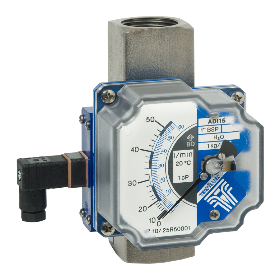
- Page 1 Instructions manual Serie AD Flow switch and indicator The art of measuring R-MI-AD15 Rev.: 3 English version...
- Page 2 PREFACE Thank you for choosing a product from Tecfluid S.A. This instruction manual allows installation, configuration, programming and maintenance. It is recommended to read it before using the equipment. WARNINGS • This document shall not be copied or disclosed in whole or in any part by any means, without the written permission of Tecfluid S.A.
-
Page 3: Table Of Contents
TABLE OF CONTENTS SERIES AD INTRODUCTION ................WORKING PRINCIPLE ..............RECEPTION .................. INSTALLATION ................1A / 2A LIMIT SWITCH INTRODUCTION ................Set point adjusment ............Electrical connection ............AMD LIMIT SWITCH INTRODUCTION ................OPERATION ................. MOUNTING THE LIMIT SWITCH IN AN EXISTING EQUIPMENT ..Kit contents ................. - Page 4 ”WRITE PROTECT” ............... MAINTENANCE ................16.1 Series AD ................16.2 Potential problems with the indicator housing ......16.2.1 The indicator pointer rubs on the reading scale ..16.2.2 Deviation of the zero on the scale ......16.3 AMD limit switch maintenance ..........16.3.1 Electrical verification ..........
-
Page 5: Series Ad
SERIES AD INTRODUCTION The series AD of flow switches and indicators are flowmeters for liquids and gases. They are very robust instruments prepared to work under extreme conditions. They can fit local flow rate indication by means of magnetic coupling, with scales calibrated in l/h, m /h, kg/h, t/h, %, etc. - Page 6 The AD15 model fits 1 or 2 reed based limit switches. The ADI15 model fits a magnetic flow indicator system using a pointer on a graduated scale. It can also fit the same limit switches as in AD15 model as well as the AMD inductive limit switches.
-
Page 7: Reception
RECEPTION The series AD flowmeters are supplied conveniently packaged for their protection during transportation and storage, together with their instructions manual for installation and operation. The instruments are supplied tested in our calibration rigs, ready for installation and service. Before installing the flowmeter, remove all the blocking elements. For models ADI, with the instrument in its working position, move the disc and check that the indicating needle moves all over the scale and returns to zero. -
Page 8: 1A / 2A Limit Switch
The "0" on the scale indicates the fluid inlet on the meter, and the end of the scale indicates the fluid outlet. 1A / 2A LIMIT SWITCH INTRODUCTION It is a SPDT reed type switch that is used to generate an alarm or an operation when the circulating flow reaches a certain value. -
Page 9: Electrical Connection
Electrical connection For the electrical installation, a multi-conductor cable should be used to obtain a good seal with the cable gland. The connector is provided with a PG 7 cable gland, suitable for a 4.5 to 7 mm outside diameter cable. Terminal 1: Common Terminal 2: Normally open (NO) Terminal 3: Normally closed (NC) -
Page 10: Amd Limit Switch
AMD LIMIT SWITCH INTRODUCTION The AMD limit switch can be used to generate an alarm or an operation when the flow rate that the instrument is measuring reaches a preset value on the scale plate. The AMD limit switch consists of a NAMUR slot type inductive sensor, that is actuated by a vane. -
Page 11: Mounting The Limit Switch In An Existing Equipment
MOUNTING THE LIMIT SWITCH IN AN EXISTING EQUIPMENT When the AMD limit switch is to be fitted to an existing device, please follow these steps. Kit contents The kit contains the following elements: AMD kit Quantity Material Position AMD limit switch circuit Self tapping screw DIN7982 B-2,2 x 9,5 Nº2 A2 AMD vane Self tapping screw DIN7982 B-2,2 x 9,5 Nº2 A2... -
Page 12: Assembling The Amd Kit
Assembling the AMD kit Slide the circuit (1) into the slot until it stops, and then screw it as shown in the figure. Slot Screw (2) Screw (2) Place the vane (3) in the position shown in the figure. The height on the shaft should be such that when the vane passes through the sensor slots, remains centered without touching them. -
Page 13: Switching Point Adjustment
Switching point adjustment At the bottom of the switching needle, the fixing nuts of the switching points can be found. To move the switching point, the fixing nuts have to be slightly loosen without removing the scale plate (see figure on the next page). After that, place the switching point at the required scale value, and fix it with the nuts. -
Page 14: Electrical Connection
Electrical connection Proceed according to section 9. Mounting Slide the scale plate into the slot until it stops as shown in the figure. Mount the cover with the four screws M4. ELECTRICAL CONNECTION For the electrical connection, the instrument is provided with a four terminal connector. For the electrical installation it is recommended to use multiple conductor cables with sections of 0.25 or 0.5 mm , in order to make it easier to connect. -
Page 15: Th6 Transmitters
TH6 TRANSMITTERS INTRODUCTION Transmitters TH6 are electronic position transducers with a microprocessor. The instrument uses the Hall effect to capture the field of a magnet. This signal, after the microcontroller processing, is converted into a current signal of 4-20 mA in a 2-wire loop. This signal is proportional to the flow rate. -
Page 16: Power Supply And Analog Output
12.1 Power supply and analog output 12 to 36 VDC The connection is made in the terminal block. The positive terminal of the power supply is connected to the position + and the positive terminal of the load in the position -. The negative terminals of the power supply and the load are connected together. -
Page 17: Hart Transmitters
HART TRANSMITTERS The TH6H transmitters have a modem for HART communication. TH6H transmitters are fully compatible with the HART Server software from HART Communication Foundation. Tecfluid S.A. do not guarantee that the TH6H transmitter is compatible with the different servers on the market. When connecting the transmitter, an external resistor (R ext.) should be included. -
Page 18: 15 "Write Protect
Summary of the main communication characteristics: Manufacturer, Model and Revision Tecfluid S.A., TH6H, Rev. 0 Device type Transmitter HART revision Device Description available Number and type of sensors Number and type of actuators Number and type of host side signals 1, 4 –... -
Page 19: Maintenance
MAINTENANCE 16.1 Series AD No special maintenance is required. 16.2 Potential problems with the indicator housing 16.2.1 The indicator pointer rubs on the reading scale To remove the cover (6), remove the four screws M4 at the corners of the indicator housing. Rubbing normally happens if the meter has been hit or dropped. -
Page 20: Amd Limit Switch Maintenance
16.3 AMD limit switch maintenance 16.3.1 Electrical verification Check that the voltage at the terminals + and - is over 7.5 V when the vane is in the slot. Connect a multimeter with the scale in DC mA, in series with the terminal +. Verify that the current is less than 1 mA when the vane is into the slot and more than 3 mA when the vane is out of the slot. -
Page 21: Technical Characteristics
TECHNICAL CHARACTERISTICS 17.1 Series AD Accuracy: ±5% full scale Scales: Direct in engineering units or in % Materials: Brass, from ¼” to 2 ½” Aluminium, from 1 ¼” to 2 ½” EN 1.4404 (AISI 316L) on request Working temperature: -20ºC ... +100ºC Working pressure: PN16 (others on request ) Connections:... -
Page 22: Safety Instructions
SAFETY INSTRUCTIONS The series AD flowmeters are in conformity with all essential requirements of all EC directives applicable to them: 2014/68/EU Pressure equipment directive (PED) Limit switches and transmitters: 2014/30/EU Electromagnetic compatibility directive (EMC) 2012/19/EU Waste electric and electronic equipment (WEEE). Equipment for hazardous areas: 2014/34/EU Equipment and protective systems intended for use... -
Page 23: Additional Instructions For The Atex Version
ADDITIONAL INSTRUCTIONS FOR THE ATEX VERSION This chapter only applies to equipment intended for use in explosive atmospheres. These equipment conform with the directive 2014/34/EU (Equipment and protective systems intended for use in potentially explosive atmospheres) as indicated in the EC-type examination certificate and in its marking. -
Page 24: Amd Limit Switch
19.3 AMD limit switch When the equipment includes an AMD limit switch, it is certified as intrinsic safety with the following parameters: Ui : 16 V Ii : 25 mA Specific parameters Pi : 64 mW Ci : 30 nF Li : 100 uH 19.4 TH6 transmitters... -
Page 25: Marking
19.5 Marking An example of marking is sown as follows. The marking of the equipment shows the following characteristics: Manufacturer Model Serial number CE marking ATEX marking Certification number Address of the manufacturer FLOW RANGES Thread Flow scales (BSP / NPT) (l/min water) 0,25 ... -
Page 26: Dimensions
DIMENSIONS Weight (kg) ¼" ½" BSP ½" NPT ¾" BSP ¾" NPT 1”BSP 1”NPT 1 ¼" 1 ½" 2” 2 ½" (dimensions in mm) - Page 27 The dimension B of the AD15 model (previous page) is valid for ADI15 Weight (kg) ¼" ½" BSP ½" NPT ¾" BSP ¾" NPT 1”BSP 1”NPT 1 ¼" 1 ½" 2” (dimensions in mm) 2 ½"...
-
Page 28: Atex Certificate
ATEX CERTIFICATE... -
Page 31: Declarations Of Conformity According To Atex
DECLARATIONS OF CONFORMITY ACCORDING TO ATEX... - Page 32 WARRANTY Tecfluid S.A. guarantee all the products for a period of 24 months from their sale, against all faulty materials, manufacturing or performance. This warranty does not cover failures which might be imputed to misuse, use in an application different to that specified in the order, the result of service or modification carried out by personnel not authorized by Tecfluid S.A., wrong handling or accident.
Need help?
Do you have a question about the AD Series and is the answer not in the manual?
Questions and answers