
Subscribe to Our Youtube Channel
Related Manuals for Durr Dental Quattro P 20


Summary of Contents for Durr Dental Quattro P 20
- Page 1 Quattro P 20 Installation and operating instructions 0297 4852100006L02 *4852100006L02*...
- Page 3 11.1 Mains connection ... . Quattro P 20 ....11.2 Main controller ....28 Quattro P 20 .
-
Page 4: Table Of Contents
Contents 12.7 Emergency mode ... . 13 Maintenance ..... 13.1 Maintenance schedule . - Page 5 These installation and operating instructions Observe the operating instructions. apply to: Quattro P 20 Order number: 4852-54; 4852100022; Disconnect all power from the unit. 4852100023 Warnings and symbols Wear ear protectors.
- Page 6 Important information Copyright information Safety All circuits, processes, names, software pro- Dürr Dental has designed and constructed this grams and units mentioned in this document are unit so that when used properly and for the inten- protected by copyright. ded purpose it does not pose any danger to The Installation and Operating Instructions must people or property.
- Page 7 Important information Electrical safety WARNING Observe and comply with all the relevant elec- ❯ Risk of explosion due to ignition of trical safety regulations when working on the combustible materials unit. Do not operate the unit in any rooms in ❯...
- Page 8 Important information 2.10 Disposal The unit must be disposed of properly. Within the European Union, the unit must be disposed of in accordance with EU Directive 2012/19/EU (WEEE). If you have any questions about the correct ❯ disposal of parts, please contact your dental trade supplier.
- Page 9 Quattro P 20 ..... 4852-54 Quattro P 20 ....4852100022 Quattro P 20 .
- Page 10 Product description Technical data Quattro P 20 Electrical data 4852-54 Rated voltage Mains frequency Nominal current at 8 bar (0.8 MPa) 17.6 19.2 Speed 1440 1700 Type of protection IP 21 Mains fuses * Max. permissible mains impedance in accordance with EN 61000‑3‑11 ** 0.13...
- Page 11 Product description Filter mesh size Sinter filter µm Coalescence filter µm 0.01 Network connection LAN technology Ethernet Standard IEEE 802.3u Data rate Mbit/s Connector RJ45 Type of connection Auto MDI-X ³ CAT5 Cable type Ambient conditions during storage and transport Temperature °C -10 to +55...
- Page 12 Product description Quattro P 20 Electrical data 4852100022 4852100023 Rated voltage Mains frequency Nominal current at 8 bar (0.8 MPa) 17.6 19.2 Speed 1440 1700 Type of protection IP 21 Mains fuses * Max. permissible mains impedance in accordance with EN 61000‑3‑11 ** 0.13...
- Page 13 Product description Filter mesh size Coalescence filter µm 0.01 Network connection LAN technology Ethernet Standard IEEE 802.3u Data rate Mbit/s Connector RJ45 Type of connection Auto MDI-X ³ CAT5 Cable type Ambient conditions during storage and transport Temperature °C -10 to +55 Relative humidity max.
- Page 14 Product description Distance between rubber feet Compressor unit type plate Membrane drying unit The type plate of the membrane drying unit is located on the side of the membrane drying unit. a (cm) b (cm) 90 l 32.5 Type plate Complete system The type plate of the overall system is located on the console.
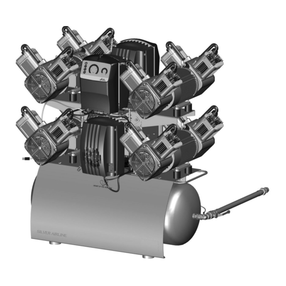
- Page 15 Product description Operation Air intake filter Compressor unit Pressure tank Safety valve Compressed air connection (3/4") Pressure gauge/display Automatic/manual condensate drain valve Sintered or coalescence filter Condensate drain valve Fuse box Membrane dryer Fine or virus bacteria filter Controller Intake connector The compressor unit draws in atmospheric air and compresses it without oil.
- Page 16 Product description Controller All of the measurement data for the unit comes together in the control (e.g. pressure in the pres- sure tank, temperature of the motor windings), where it is then evaluated. Likewise, various set- tings (e.g. switch-on/cut-off pressure) can be adjusted, or the unit can be connected via the network to monitoring software.
- Page 17 Assembly Assembly ≥ 40 °C Requirements The unit must not be set up or operated within the vicinity of the patients (within a radius of 1.5 m). The unit can be installed either at the same level as the surgery room or on a floor below (e.g. cel- lar).
- Page 18 Assembly Transport Installation Installing the compressor unit WARNING Place the pressure tank with the rubber feet in ❯ Risk of explosion of the pressure tank the rubber pads. and pressure hoses The pressure tank and the pressure ❯ hoses must be vented before they are stored or transported.
- Page 19 Assembly Attach the compressor units with the lock Attach the crossbeam to the console with a ❯ ❯ washers and nuts. lock washer and screw. Hook the fuse box in the keyholes and attach it ❯ Connect the compressor units via the pressure ❯...
- Page 20 Assembly Attach the compressor units with the lock Connect the hoses of the pressure tank to the ❯ ❯ washers and nuts. outlet of the membrane dryers (OUT). Connect the compressor units via the pressure ❯ hose to the upper connections of the coolers. Attach the membrane dryer to the pressure ❯...
- Page 21 Assembly Connect the hoses of the lower connections of ❯ Warning – risk of dangerous electric vol- the coolers to the inlet of the membrane dryers tages (IN). The mains plug must not be plugged in. If it is ❯ plugged in, unplug it.
- Page 22 Assembly Lay the cables of the lower compressor units Plug the temperature sensor connector and ❯ ❯ and the free cable of the distribution box the power supply of the compressor units into upwards to the main controller. Then guide it the sockets provided.
- Page 23 Assembly Insert the Dürr Connect transition piece into the Secure the connection hose of the membrane ❯ ❯ drain pipe. dryer to the free drop section with the hose clip. If the Dürr Connect connector interface (DN 40) included in the scope of delivery does not fit the existing drain pipe, addi- tional connector interfaces can be pur- chased from Dürr Dental.
- Page 24 Assembly Connect the pressure hose with the supplied ❯ DANGER connecting sleeve to the pipe system. Risk of electric shock due to defective mains cable Mains cables must not be allowed to ❯ come into contact with any hot surfa- ces on the unit.
- Page 25 Assembly – Display parameters Establishing the electrical connections – Select operating modes DANGER – Indicate messages and error situations Risk of electric shock due to defective – Change unit settings mains cable – Activate test functions Mains cables must not be allowed to ❯...
- Page 26 Assembly Commissioning Read off the pressure when the unit starts up. ❯ If the readings deviate from the values preset at In many countries technical medical prod- the factory, adjust the values to the factory set- ucts and electrical devices are subject to tings.
- Page 27 Assembly Turn the screw clockwise as far as it will go. Network configuration ❯ The valve must now be closed again. Various options are available for network configu- Press and hold the service key until the ration: ❯ ü Automatic configuration via DHCP (recommen- safety valve triggers.
- Page 28 Assembly 10 Adjustment options 10.1 Adjustment of the switch- on/cut off pressure WARNING Risk of explosion of the pressure ves- The pressure vessels used in the com- pressors are designed to withstand continuous pressure changes of 2 bar and can be used continuously under these pressure changes.
- Page 29 Assembly 11 Controller 11.1 Mains connection L1.1 L2.1 L3.1 PE.1 L1.2 L2.2 L3.2 PE.2 Mains connection 3/N/PE AC 400 V Fuse C16A Fuse C16A 4852100006L02 2105V006...
- Page 30 Assembly 11.2 Main controller L1.2 L2.2 PE.2 L3.2 -X101 -X13 N -X14 -X10 -X15 Fuse T10AH/T12AH* Fuse T10AH/T12AH* Fuse T10AH/T12AH* Fuse T10AH/T12AH* Fuse T10AH/T12AH* Fuse T10AH/T12AH* 4852100006L02 2105V006...
- Page 31 Assembly Fuse T1.6AH Status indicator LEDs for temperature sensor, compressor unit 1 Status indicator LEDs for temperature sensor, compressor unit 1 Status indicator LEDs for temperature sensor, compressor unit 1 Status indicator LEDs for temperature sensor, compressor unit 2 Status indicator LEDs for temperature sensor, compressor unit 2 Status indicator LEDs for temperature sensor, compressor unit 2 Compressor unit 1 Compressor unit 2...
- Page 32 Assembly 11.3 Auxiliary controller L1.1 L2.1 PE.1 -X101 L3.1 -X13 N -X14 -X10 -X15 Fuse T10AH/T12AH* Fuse T10AH/T12AH* Fuse T10AH/T12AH* Fuse T10AH/T12AH* Fuse T10AH/T12AH* Fuse T10AH/T12AH* Fuse T1.6AH Status indicator LEDs for temperature sensor, compressor unit 3 4852100006L02 2105V006...
- Page 33 Assembly Status indicator LEDs for temperature sensor, compressor unit 3 Status indicator LEDs for temperature sensor, compressor unit 3 Status indicator LEDs for temperature sensor, compressor unit 4 Status indicator LEDs for temperature sensor, compressor unit 4 Status indicator LEDs for temperature sensor, compressor unit 4 Compressor unit 3 Compressor unit 4 Cooling fan motor, membrane drying unit 3...
- Page 34 Usage Pressure range Usage The pressure is displayed and can be adjusted in this area. The pressure is displayed via: 12 Operation 1. LED (£ 4.5 bar): Lights up continuously, even with a pressure Prior to working on the unit or in case of <...
-
Page 35: Emergency Mode
Usage The fault can be acknowledged by pressing the button, as a result of which emergency mode is activated. Fault button, LED lights up As well as faults, the LED on the fault button also lights up to indicate warning messages. These cannot be acknowledged. -
Page 36: Maintenance
Usage 13 Maintenance Prior to working on the unit or in case of danger, disconnect it from the mains. WARNING Risk of infection due to burst filters Particles enter the compressed air network and can therefore enter the mouth of the patient. Replace filters in accordance with the maintenance schedule. - Page 37 Usage Information about replacement parts is available from the portal for authorised specialist dealers www.duerrdental.net 4852100006L02 2105V006...
-
Page 38: Changing The Filter
Usage Replacing the fine or virus bacteria filter 13.3 Changing the filter Unscrew and remove the filter cover. ❯ Remove the filter. ❯ NOTICE Insert a new filter. ❯ Shortened service life, bad air quality, Replace the filter cover and close. ❯... -
Page 39: Taking Out Of Use
Usage Press for at least 2 seconds. The unit is 14 Taking out of use ❯ now in setup mode. LED is flashing. 14.1 Taking the unit out of use Press to confirm filter replacement. ❯ Resetting the unit to standby mode: Wear ear protectors. -
Page 40: Storage Of The Unit
Usage At maximum tank pressure, slowly open the Close condensate drain valves on the drying ❯ ❯ condensate drain valve. units. Once the start-up pressure has been reached the Disconnect the compressor from the pipe sys- ❯ compressor unit will switch on. tem. -
Page 41: Troubleshooting
Troubleshooting Troubleshooting 15 Tips for operators Any repairs exceeding routine maintenance may only be carried out by qualified personnel or our service. Prior to working on the unit or in case of danger, disconnect it from the mains. Error Possible cause Remedy The operating panels of the Fault in communications... - Page 42 Troubleshooting Error Possible cause Remedy Compressor does not switch Excessive air extraction Check air requirements and ❯ dimensioning of the compres- off or has difficulty reaching the cut off pressure sor. Air intake filter dirty Replace the air intake filter. ❯...
-
Page 43: Tips For Service Technicians
Troubleshooting 16 Tips for service techni- cians 16.1 Notes on repairs If a unit has failed and needs to be replaced, this can be done while the system is running. To do so, the following steps must be observed: ü Emergency mode is activated ü... -
Page 44: Appendix
Appendix Appendix 17 Handover record This document confirms that a qualified handover of the medical device has taken place and that appropriate instructions have been provided for it. This must be carried out by a qualified adviser for the medical device, who will instruct you in the proper handling and operation of the medical device. Product name Order number (REF) Serial number (SN) - Page 45 Appendix 4852100006L02 2105V006...
- Page 48 Hersteller / Manufacturer: DÜRR DENTAL SE Höpfigheimer Str. 17 74321 Bietigheim-Bissingen Germany Fon: +49 7142 705-0 www.duerrdental.com info@duerrdental.com...
Need help?
Do you have a question about the Quattro P 20 and is the answer not in the manual?
Questions and answers