Table of Contents
Advertisement
Quick Links
Advertisement
Table of Contents

Subscribe to Our Youtube Channel
Related Manuals for Durr Dental PTS 195


Summary of Contents for Durr Dental PTS 195
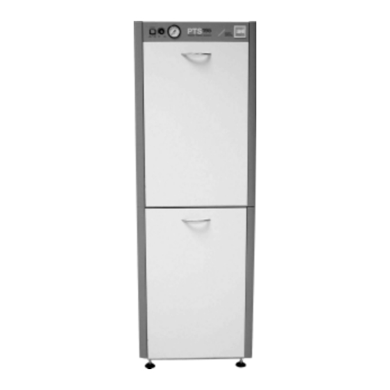
- Page 1 INSTALLATION AND OPERATING INSTRUCTIONS DÜRR PTS 195 2002/07...
-
Page 3: Table Of Contents
CONTENT Important Information 1. Notes ............4 10. Dry air system installation ....16 1.1 CE - Labelling ........4 10.1 Pressure hose between 1.2 Guidelines ......... 4 pressure tank and dry air unit ..17 1.3 General notes ........4 11. -
Page 4: Important Information
• These Installation and Operating Instructions possible danger. form an integral part of the unit. They must be • When using the PTS 195 all local and kept close to the unit and in readiness relevant regulations must be observed! whenever required. -
Page 5: Electrical Safety Notes
1.5 Electrical Safety Notes CE-Labeling • The PTS 195 may only be connected to a fixed power outlet connected to the mains supply. Warning! Hot surface • Before connecting the appliance to the power supply check that the electrical Check environment. -
Page 6: Product Information
2. PRODUCT INFORMATION 2.1 Correct Usage The PTS 195 is designed for providing compressed air and vacuum for dental units or similar applications, and according to model for amalgam separation. Correct usage implies the observance of the operating instructions as well as installation, operating and maintenance procedures. -
Page 7: Contents
3. CONTENTS Power Tower PTS195/11 Power Tower Silence PTS195/01 0948-195/11 0948-195/01 V 900, 1 Compressor Power Unit V 900, 1 Compressor Power Unit with V 900, 1 Compressor Power Unit V 900, 1 Compressor Power Unit V 900, 1 Compressor Power Unit with VS 900 VS 900 VS 900... -
Page 8: Special Accessories
Power Tower PTS195/13 Power Tower PTS195/22 0948-195/13 0948-195/22 with V 1200, 2 Compressor Power Units V 1200, 2 Compressor Power Units V 1200, 2 Compressor Power Units V 1200, 2 Compressor Power Units V 1200, 2 Compressor Power Units with VS 600, 1 Compressor Power Unit VS 600, 1 Compressor Power Unit VS 600, 1 Compressor Power Unit VS 600, 1 Compressor Power Unit... -
Page 9: Technical Specifications
Typ PTS 195/22 Typ PTS 195/22 Typ PTS 195/22 Typ PTS 195/22 Typ PTS 195/01 and PTS 195/02 Typ PTS 195/01 and PTS 195/02 Typ PTS 195/01 and PTS 195/02 Typ PTS 195/01 and PTS 195/02 Typ PTS 195/01 and PTS 195/02... -
Page 10: Functional Description
5. FUNCTIONAL DESCRIPTION 5.1 Compressor power unit The compressor power unit starts up auto- Detailed descriptions of the functions matically when the pressure in the vessel of the individual units can be found in reaches 5.5 bar and is switched off at 7.5 the appropriate installation and bar. -
Page 11: Installation
If this is not possible dispose of the packing in an environmentally correct way. The transport carton can be disposed of as paper waste. The PTS 195 must be transported in pressure-free state. Before transport empty the compressor tank and bleed the hoses. -
Page 12: Set-Up And Commissioning
7. SET-UP AND COMMISSIONING Set-up and commissioning should only be carried out by an authorized technician. 7.1 Environmental Requirements • The appliance should only be installed and operated in a well-ventilated, dry and dust- free room. • The PTS must be installed in a position that allows the identification plate to be easily visible at all times and where easy access for repairs and maintenance is provided. -
Page 13: Suction Unit - Set-Up And Connection
8. SUCTION UNIT – SET-UP AND CONNECTION 8.1 Removal of Transport Safety Clips • The suction unit should be unpacked and the clips used for safety during transport, (1) and (2), must be removed. 8.2 Suction Unit Set-up When setting up the Power Tower Silence, allow a distance of approx. -
Page 14: Suction Unit Cover Conversion
• Use cover (7) to close connection. The ventilation openings (x) must not be covered, otherwise there is danger of the power unit overheating. 8.4 Suction Unit cover conversion • Loosen the screws on the cover (8) and remove cover. Retain the screws for later use. -
Page 15: Compressor Module Set-Up
• Place the cover (8) back onto the suction unit. Do not tighten at this stage. 9. COMPRESSOR MODULE SET- • Place the compressor module on top of the suction unit and screw loosely into place using the 16 M5x16 screws (12). •... -
Page 16: Dry Air System Installation
10. DRY AIR SYSTEM INSTALLATION • Place the dry air unit (14) into the place allo- cated for it in the PTS unit and secure using the 4 toothed washers and the M4 nuts supplied, see figs. 13 and 14. •... -
Page 17: Pressure Hose Between Pressure Tank And Dry Air Unit
• Attach the prepared condensated water drainage hose (15) together with ring (16) and the 2 M4 nuts (17) onto the head of the dry air unit. • The condensated water drainage hose must now be positioned to feed into the collector (19) supplied and secured. -
Page 18: Suction Hoses Installation
11. SUCTION HOSES INSTALLATION • The gray hose supplied (25) in which either 2 or 4 black hoses (23) are encased (depending on model of PTS supplied) must now be connected to the rear of the PTS using cable ties (24, 26). See figs. 19 and The hose (25) must be placed so far down that the compressor power unit is able to take in cooler air from the... -
Page 19: Cable Laying - Compressor To Suction Unit
13. CABLE LAYING – COMPRESSOR TO SUCTION UNIT When laying cables and hoses inside the PTS be sure to use the notched cable tie, cable conduits and openings and observe the instructions for positioning. This will ensure that cables and hoses to not come into contact with hot surfaces or become damaged due to vibration. -
Page 20: Compressor Power Unit
14. COMPRESSOR POWER UNIT 14.1 230V/400V Versions - installation and connection • Place the power unit onto the rubber vibration pads already pre-positioned and secure with washers and nuts. Place the power unit into the PTS in such a way that the cable (43) points to the left. - Page 21 • Place the power unit into the PTS and secure with washers and nuts. Place the power unit in such a way that the connecting cable points inwards (43). This provides for a reduction in vibration due to the counter-operation of the power unit. •...
-
Page 22: Connection Of Air Supply Hose To Compressor Tank
14.3 Connection of air supply hose to compressor tank • Slide the flexible compressed air hose (8x3x14) onto the end of the quick-release coupling (50) and secure against slipping using a cable clamp. Ensure when laying the flexible compressed air hose that sufficient distance is maintained between this and other cables and hoses. -
Page 23: Commissioning
15. COMMISSIONING • The power cable of the PTS should be connected to the power supply. (From terminal X13 on control PCB.) If connection to the mains is via false floor or ceiling, then a universal separator must be located in the circuit (universal switch or universal line safety switch (fuse)) with >3mm contact opening. - Page 24 • Remove suction hose from the hose manifold or rinse the spittoon, the suction unit starts up. Shut off spittoon or replace suction hose in hose manifold, the suction unit then switches off. The VS-suction units will continue to operate for approx. 30 seconds. •...
-
Page 25: Electrical Layout
16. ELECTRICAL LAYOUT 16.1 Model 400V 3~ amalgamrecycling amalgamrecycling POWER POWER TOWER SILENCE trocken feucht DÜRR DÜRR MARCHE ARRÊT humide DENTAL DENTAL U PE V W U PE V W L PE N U PE V W L1 L2 PE L3 U1 V1 W1 PE PE U V W U1 V1 W1 PE... -
Page 26: Model 230V 1
16.2 Model 230V 1~ amalgamrecycling amalgamrecycling POWER POWER TOWER SILENCE trocken feucht DÜRR DÜRR MARCHE ARRÊT humide DENTAL DENTAL 3 2 1 L N PE L N PE L N PE L N PE L N PE L N PE L N PE... -
Page 27: Circuit Diagram
17. CIRCUIT DIAGRAM 17.1 Model 400V 3~... -
Page 31: Model 230V 1
17.2 Model 230V 1~... -
Page 35: Unit Connections
18. UNIT CONNECTIONS POWER POWER TOWER SILENCE trocken feucht MARCHE ARRÊT humide... -
Page 36: Use
19. OPERATION • Main on / off switch (61) of the PTS • Amalgam separator display (44) see „Operating Instructions DÜRR Amal- gam Separator 7800/7801“ 9000-605-65 20. MAINTENANCE The various maintenance procedures for the Suction Unit, Cleaning and Disinfecting of Suction Unit, Dry Air Unit and the Amalgam Separator can be found in the additional instruction leaflets supplied. -
Page 37: Troubleshooting
TROUBLESHOOTING 21. COMPRESSOR MOTOR FAILURE Where the PTS is fitted with two compressor power units, then the unit can be used running on one power unit as follows. • Switch off PTS at main switch (61), see fig. 37. • Operation of the switch S2 (51) to position 1. •...
Need help?
Do you have a question about the PTS 195 and is the answer not in the manual?
Questions and answers