Durr Dental Duo Tandem Installation And Operating Instructions Manual
Hide thumbs
Also See for Duo Tandem:
- Installation and operating instructions manual (48 pages) ,
- Installation and operating instructions manual (44 pages) ,
- Installation and operating instructions manual (48 pages)

Related Manuals for Durr Dental Duo Tandem


Summary of Contents for Durr Dental Duo Tandem
- Page 1 Duo Tandem / Quattro Tandem Installation and operating instructions 0297 9000-610-72/30 *9000-610-72/30*...
- Page 3 ..... . Duo Tandem ....
-
Page 4: Table Of Contents
Contents 12.5 Auxiliary operation ... . 12.6 Set-up mode ....12.7 Fault ..... . 12.8 Emergency mode . - Page 5 These installation and operating instructions apply to: Observe the operating instructions. Duo Tandem Order number: 4152-54; 4252-54 Disconnect all power from the unit. Quattro Tandem Order number: 4642-54; 4682-54; 4682100001...
- Page 6 Important information The Installation and Operating Instructions must Safety not be copied or reprinted, neither in full nor in Dürr Dental has designed and constructed this part, without written authorisation from Dürr unit so that when used properly and for the Dental.
- Page 7 Important information Electrical safety WARNING Observe and comply with all the relevant elec- ❯ Risk of explosion due to ignition of trical safety regulations when working on the combustible materials unit. Do not operate the unit in any rooms in ❯...
- Page 8 Important information 2.10 Disposal The unit must be disposed of properly. Within the European Union, the unit must be disposed of in accordance with EU Directive 2012/19/EU (WEEE). If you have any questions about the correct ❯ disposal of parts, please contact your dental trade supplier.
- Page 9 Sterile filter ....1640-981-00 Duo Tandem 400 V, 3~, with 1 com- Sintered filter ....1650-101-00...
- Page 10 Product description Technical data Duo Tandem Electrical data 4152-54 4252-54 Rated voltage Mains frequency Nominal current at 8 bar (0.8 MPa) Speed 1410 1690 1410 1690 Type of protection IP 21 IP 21 Mains fuses * Circuit breaker fuse characteristics B, C or D in acc. with EN 60898-1...
- Page 11 Product description Network connection Standard IEEE 802.3u Data rate Mbit/s Connector RJ45 Type of connection Auto MDI-X ³ CAT5 Cable type Ambient conditions during storage and transport Temperature °C -10 to +55 Relative humidity max. 95 Ambient conditions during operation Temperature °C +10 to +40...
- Page 12 Product description Quattro Tandem Electrical data 4642-54 4682-54 4682100001 Rated voltage Mains frequency Nominal current at 8 bar (0.8 MPa) Speed 1440 1700 1440 1700 Type of protection IP 21 IP 21 Mains fuses * Max. permissible mains impedance in £...
- Page 13 Product description Network connection LAN technology Ethernet Standard IEEE 802.3u Data rate Mbit/s Connector RJ45 Type of connection Auto MDI-X Cable type ³ CAT5 Ambient conditions during storage and transport Temperature °C -10 to +55 Relative humidity max. 95 Ambient conditions during operation Temperature °C +10 to +40...
- Page 14 Product description Compressor unit Distance between rubber feet The type plate of the compressor unit is located Distances between the rubber feet for different on the crankcase below the cylinder. pressure vessel volumes: Compressor unit type plate Membrane drying unit a (cm) b (cm) The type plate of the membrane drying unit is...
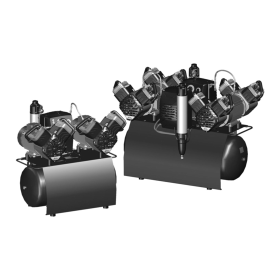
- Page 15 The compressor unit draws in atmospheric air and compresses it without oil. It then transports the oil-free compressed air to the membrane dry- Duo Tandem / Quattro ing unit. The cooler and the membrane dryer Tandem extract moisture from the compressed air. The oil-free, hygienic and dry air is stored in the pres- sure tank ready for use in connected devices.
- Page 16 Product description Operating panel 2 3 4 Fault button with orange LED Filter change button with orange LED Service key with blue LED Standby button with blue LED Pressure range display/adjustment Pressure dew point display Different messages and the status of the unit are displayed on the operating panel.
- Page 17 Assembly Assembly ≥ 40 °C Requirements The unit must not be set up or operated within the vicinity of the patients (within a radius of 1.5 m). The unit can be installed either at the same level as the surgery room or on a floor below (e.g. cel- lar).
- Page 18 WARNING Risk of explosion of the pressure tank The transport locks only need to be and pressure hoses removed on the Duo Tandem, as the compressor units are delivered separately The pressure tank and the pressure ❯ for the Quattro Tandem.
- Page 19 Assembly Place the compressor units on the vibration Connect the compressor unit with the mem- ❯ ❯ reducers with the motor terminal box facing brane drying unit via the pressure hose. towards the control. Warning – risk of dangerous electric volt- ages The mains plug must not be plugged in.
- Page 20 Assembly Establishing the compressed When routeing the cables, maintain the air connection correct gaps between control cables and supply cables. The supplied flexible pressure hose Guide the cables of the compressor units ❯ between the pipe system and the com- through the strain relief and fasten.
- Page 21 Assembly Place a collector tray under every membrane ❯ drying unit. Network connection Place a collector tray under- Purpose of the network connection neath The network connection is used to exchange information or control signals between the unit During operation, condensed water is continu- and a software installed on a computer, in order ously collected in the membrane-drying unit and to, e.
- Page 22 Assembly Connect to the computer network with the net- Connect the mains plug to an earthed power ❯ ❯ work cable. outlet. The unit will start immediately when the mains DHCP plug is connected. Check whether the power outlet is switched via ❯...
- Page 23 Assembly Connect the network cable to the network The device is operated via the operating panel of ❯ socket X10. the main control. The auxiliary control is inactive (standby button flashing) and cannot be oper- Guide the cable through the cable holder and ❯...
- Page 24 Assembly Commissioning Fill the pressure tank to the cut-off pressure. ❯ WARNING In many countries technical medical prod- ucts and electrical devices are subject to Risk of damage to the safety valve regular checks at set intervals. The owner Risk of explosion of the pressure tank must be instructed accordingly.
- Page 25 Assembly Draining the condensation water During transport, condensation water can accu- mulate in the pressure tank due to changes in temperature. This also applies to compressors with a mem- brane drying unit. At maximum tank pressure, slowly open the ❯ condensate drain valve.
- Page 26 Assembly Check the firewall and release the ports, if 10 Adjustment options ❯ applicable. 10.1 Adjustment of the switch- Network protocols and ports on/cut off pressure Port Purpose Service 45123 UDP, Unit recognition and WARNUNG 45124 UDP configuration Risk of explosion of the pressure ves- 1900 UDP Service detection SSDP /...
- Page 27 Assembly Use the service key to confirm. ❯ If no touch pulse is received for 30 sec- onds, the system will automatically switch to standby operation. The settings are not saved. 9000-610-72/30 1907V007...
- Page 28 Assembly 11 Controller PE L2 X101 F1 F2 F3 F5 F6 Fuse T10AH Fuse T10AH Fuse T10AH Fuse T10AH Fuse T10AH Fuse T10AH Fuse T1.6AH Status indicator LED for temperature sensor, compressor unit 1 Status indicator LED for temperature sensor, compressor unit 1 Status indicator LED for temperature sensor, compressor unit 1 Status indicator LED for temperature sensor, compressor unit 2 Status indicator LED for temperature sensor, compressor unit 2...
- Page 29 Assembly Fan motor, compressor cabinet (Duo Tandem only) Fan motor, compressor cabinet (Duo Tandem only) Switch, main controller/auxiliary controller Temperature sensor, compressor unit 1 Temperature sensor, compressor unit 2 Connection, compressor unit 1 Connection, cooling fan motor, membrane drying unit 1...
- Page 30 Usage Service key Check of the safety valve Usage and adjustment of the pres- sure range (see "9.2 Checking the safety valve" 12 Operation and "10.1 Adjustment of the switch-on/cut off pres- Prior to working on the unit or in case of sure").
-
Page 31: Auxiliary Operation
Usage 12.2 Switching the unit on/off 12.5 Auxiliary operation Switch the unit on and off via the surgery main If two compressors are operated in a singled ❯ switch. compressed air network, then the two controls The compressor unit will start up automatically need to be configured as a main control and an and fill the pressure tank. - Page 32 Usage Have the necessary repairs to the unit carried ❯ out. 9000-610-72/30 1907V007...
-
Page 33: En 13 Maintenance
Usage 13 Maintenance Prior to working on the unit or in case of danger, disconnect it from the mains. VORSICHT Risk of infection due to burst filters Particles enter the compressed air network and can therefore enter the mouth of the patient. Replace filters in accordance with the maintenance schedule. -
Page 34: Changing The Filter
Usage Remove the air intake filter. ❯ 13.2 Changing the filter ACHTUNG Shortened service life, bad air quality, reduced delivery Replace the filter 1x per year or as ❯ soon as the yellow LED lights up. Filter replacement button, yellow LED lights As soon as the LED lights up, it can be temporarily switched off by pressing the button. -
Page 35: 14 Taking Out Of Use
Usage Replace the filter housing and close. 14 Taking out of use ❯ 14.1 Taking the unit out of use If the compressor is not to be used for a longer period of time, it is recommended that the unit be properly shut down and taken out of operation. -
Page 36: Storage Of The Unit
Usage At maximum tank pressure, slowly open the Close the condensate drain valve on the pres- ❯ ❯ condensate drain valve. sure tank. Once the start-up pressure has been reached the Close the condensate drain valve on the mem- ❯ compressor will switch on. - Page 37 Usage Protect the unit against moisture, dirt and ❯ extreme temperatures during transport (refer to the section on "Ambient conditions"). Only store the unit when it has been completely ❯ emptied. 9000-610-72/30 1907V007...
-
Page 38: Troubleshooting
Troubleshooting Troubleshooting 15 Tips for operators and service technicians Any repairs exceeding routine maintenance may only be carried out by qualified personnel or our service. Prior to working on the unit or in case of danger, disconnect it from the mains. Error Possible cause Remedy... - Page 39 Troubleshooting Error Possible cause Remedy Compressor does not switch Excessive air extraction Check air requirements and ❯ dimensioning of the compres- off or has difficulty reaching the cut off pressure sor. Air intake filter dirty Replace the air intake filter. ❯...
-
Page 40: Appendix
Appendix Appendix 16 Handover protocol This document confirms the qualified handover and provision of instructions for the medical device from Dürr Dental. This must be carried out by a qualified adviser for the medical device, who will instruct you in the proper handling and operation of the medical device. Product name Order number (REF) Serial number (SN) - Page 44 Hersteller/Manufacturer: DÜRR DENTAL SE Höpfigheimer Str. 17 74321 Bietigheim-Bissingen Germany Fon: +49 7142 705-0 www.duerrdental.com info@duerrdental.com...
Need help?
Do you have a question about the Duo Tandem and is the answer not in the manual?
Questions and answers