
Subscribe to Our Youtube Channel
Related Manuals for Durr Dental V 600


Summary of Contents for Durr Dental V 600
- Page 1 Suction units V 900 S, V 1200 S V 600 V 300 S Installation and Operating Instructions 0297 9000-606-89/30 ...
-
Page 3: Table Of Contents
4�2 V 600 � � � � � � � � � � � � � � � � � � � � � � 10 11�1 After every treatment � � � � � � � � � � � 23 4�3... - Page 4 Contents Appendix 15 Information about EMC in accordance with EN 60601-1-2 � � � � � � 28 15�1 General information � � � � � � � � � � � � 28 15�2 Abbreviations � � � � � � � � � � � � � � � � 28 15�3 Guidelines and manufacturer's information �...
-
Page 5: Important Information
Important information About this document Other symbols These symbols are used in the document and These installation and operating instructions on or in the unit: form part of the unit� Note, e�g� specific instructions regarding If the instructions and information in efficient and cost-effective use of the unit�... -
Page 6: Safety
Important information Safety 2.4 General safety information When operating this device always observe all Dürr Dental has designed and constructed this guidelines, laws, and other rules and regula- device so that when used properly and for the tions that are applicable at the site of opera- intended purpose there is no danger to people tion�... -
Page 7: Qualified Personnel
Important information 2.6 Qualified personnel 2.10 Disposal Operation The unit may be contaminated� Instruct the company disposing of the waste to Persons who operate the units must ensure safe take the relevant safety precautions� and correct handling based on their training and knowledge�... -
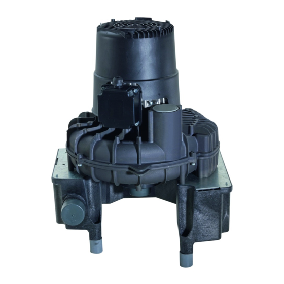
Page 8: Product Description
Product description Overview Suction unit Control box Set of connection fittings Suction hose Exhaust air hose Auxiliary air valve Condensation separator Connection pipes Waste hose LW 20 9000-606-89/30 1711V001... -
Page 9: Scope Of Delivery
3.2 Special accessories The following optional items can be used with V 600, 230 V, 1~, 50 Hz ..7127-01/002 the device: V 600, 400 V, 3~, 50/60 Hz ..7127-02/002 V 300 S V 600, 230 V, 3~, 50/60 Hz . -
Page 10: Technical Data
Product description Technical data 4.1 V 300 S Electrical data 7119-01 7119-02 Nominal voltage 230, 1~ 230, 1~ Mains frequency Nominal current 2�9 2�9 3�7 Starting current 8�2 8�2 9�1 Motor protection Motor winding overheat protector 160 °C (±5 °C) Rated power Type of protection IP 24... - Page 11 Product description Ambient conditions during storage and transport Temperature °C -10 to +60 Relative humidity < 95 Ambient conditions during operation Temperature °C +10 to +40 Relative humidity < 70 Classification Medical Devices Directive (93/42/EU) Class IIa 9000-606-89/30 1711V001...
- Page 12 Product description 4.2 V 600 Electrical data 7127-01 Nominal voltage 230, 1~ Mains frequency Nominal current 5�0 Starting current Motor protection * Rated power 1100 Type of protection IP 24 Protection class Recommended setting values� As the motor protection switch is subject to tolerances, current levels should be measured during installation and the motor protection setting adjusted accord- ingly�...
- Page 13 Product description 4.3 V 600 Electrical data 7127-02 Nominal voltage 400, 3~ 230, 3~ Mains frequency Nominal current 1�8 2�3 3�1 4�1 Starting current Motor protection * 2�5 4�0 3�5 4�5 Rated power 1000 1420 Type of protection IP 24 Protection class Recommended setting values�...
- Page 14 Product description 4.4 V 900 S Electrical data 7131-01 7131-02 Nominal voltage 230, 1~ 230, 3~ 400, 3~ Mains frequency Nominal current 7�4 6�3 3�6 Starting current Motor protection * 6�3 4�0 Rated power 1680 1970 Type of protection IP 24 Protection class Recommended setting values�...
- Page 15 Product description 4.5 V 1200 S Electrical data 7136-02 7136-03 Nominal voltage 230, 3~ 400, 3~ 230, 3~ 400, 3~ Mains frequency Nominal current 6�5 3�8 6�8 3�9 Starting current Motor protection * 6�3 4�0 7�0 4�0 Rated power 2000 2400 Type of protection IP 24...
-
Page 16: Type Plate
V 300 S turbine housing� The type plate is is located on the noise reduc- tion hood� Type plate V 600 Type plate The type plate is located on the top part of the turbine housing� 4.7 Conformity assessment This device has been subjected to conformity acceptance testing in accordance with the cur- rent relevant European Union guidelines�... -
Page 17: Operation
An auxiliary air valve in the condensate separator (V 600, V 900 S, V 1200 S models only) protects the suction unit from overheating, and also ensures smooth and even suction power�... -
Page 18: 9000-606-89/30 1711V001
Product description When an appropriate vacuum for the machine is applied, approx� 300 l air/min� is sucked in through the suction cannula� The exhaust air from the suction unit should be guided out of the building (via the roof where possi- ble)�... -
Page 19: Installation
Installation Requirements 6.4 Hose materials For waste connections and suction lines only The unit can be installed either on the same lev- use the following hose types: el as the surgery or on a floor below� – Flexible spiral hoses made of PVC with inte- Further information can be found in our grated spiral or equivalent hoses suction planning information leaflet�... -
Page 20: System Components
Installation System components The following table lists the minimum diameters of the connections in relation to the current con- The system components listed below are re- sumption: quired or recommended for various procedures Current consumption of Cross-section or for installation� unit [A] 7.1 Control box >... -
Page 21: Installation
Installation Installation The actual connection can vary depending on the chosen installation option� The connection shown is only an example� 8.1 Installation and routeing of hoses and pipes Establish connections between the pipe system and the unit using the flexible hoses supplied� This will prevent vibrations from being transmitted to the pipe system�... - Page 22 Installation V 900 S, V 1200 S Hose clamp 40-60 mm Suction hose ∅ 50 mm Elbow DN 50 / 87 Waste air pipe (aluminium)∅ 50 mm inside Hose sleeve Hose clip ∅ 28 mm Waste water hose ∅ 20 mm (internal) 9000-606-89/30 1711V001...
-
Page 23: Electrical Connections
Installation Electrical connections 400 V 3/N/PE 230 V 3/N/PE NOTICE Short circuit due to defective lead Do not route wires near hot surfaces� Before connecting, check that the power sup- ply voltage matches the voltage specifications on the type plate� The connection of the unit to the mains power supply must be done by means of a perma- nent connection�... -
Page 24: Commissioning And First Start-Up
Installation 10 Commissioning and first start-up Turn on the unit power switch or the main sur- gery switch� Carry out a function check of the system� Check all connections for leak tightness� Carry out an electrical safety check in accord- ance with applicable regulations (e�g�... -
Page 25: Operation
Operation 11 Disinfection and cleaning 11.3 Once or twice a week before the midday break NOTICE Under harsher conditions (e�g� hard water Device malfunctions or damage due or frequent use of prophylaxis powders) to use of incorrect media 1x daily before the midday break Guarantee claims may become invalid The following are required for cleaning: as a result�... -
Page 26: Maintenance
Every 2 years Check waste valve on condensation separator and replace it if neces- sary� * Only by customer services service technicians� 12.2 V 600, V 900 S, V 1200 S Maintenance interval Maintenance work Every 1-2 years Replace bacteria filter (where fitted)� * Every 2 years Check auxiliary air valve function and clean or replace it if necessary�... -
Page 27: Troubleshooting
Troubleshooting 13 Tips for operators and service technicians Any repairs above and beyond routine maintenance must only be carried out by suitably quali- fied personnel or by one of our service technicians� WARNING Infection due to contaminated unit Clean and disinfect the suction before working on the unit� Wear protective equipment when working (e� g�... - Page 28 Troubleshooting Fault Probable cause Solution Suction performance too Coarse filters in system clogged Clean coarse filters� (e�g� at separator devices) Leak in the suction line Check and if necessary establish leak-tightness of suction system and connections� * Mechanical sluggishness of tur- Disassemble the unit and clean bine caused by soiling the turbine�...
-
Page 29: Transporting The Unit
Troubleshooting 14 Transporting the unit WARNING Infection due to contaminated unit Disinfect the unit before transport� Close all media connections� Wear protective equipment to avoid any risk of infection (e�g� liquid-tight protec- tive gloves, protective goggles, face mask)� Before disassembly, clean and disinfect the suction unit and the unit using a suitable disin- fectant approved by Dürr Dental�... -
Page 30: Accordance With En 60601-1-2
Appendix The following information only applies to the V 300 S� 15 Information about EMC in accordance with EN 60601-1-2 15.1 General information The information in this leaflet includes excerpts from the relevant European standards for electrical, medical devices� It must be observed when installing Dürr Dental devices or combining them with products of other manufacturers�... - Page 31 Appendix Resistance to electromagnetic interference (immunity) for all devices and systems The device is designed for use in electromagnetic environments specified below� The customer or op- erator of the device should ensure that the device is operated such an environment� Interference immu- IEC 60601 - test Compliance level...
- Page 32 Appendix Electromagnetic interference immunity for devices or systems that are not life-sustaining Portable and mobile communication devices should not be used any closer to the unit (including ca- bles) than the recommended safety distance, which is calculated based on the applicable formula for the transmission frequency�...
- Page 33 Appendix Recommended safety distance between portable and mobile HF communication devices and the unit The device is designed for use in the electromagnetic environments specified below, in which the HF disturbance variables are controlled� The customer or the operator of the device can help to prevent electromagnetic interference by maintaining the minimum distances between mobile HF communica- tion equipment (transmitters) and the device as recommended below in accordance with the maxi- mum output line of the communication equipment�...
- Page 36 Hersteller/Manufacturer: DÜRR DENTAL SE Höpfigheimer Str. 17 74321 Bietigheim-Bissingen Germany Fon: +49 7142 705-0 www.duerrdental.com info@duerrdental.com...
Need help?
Do you have a question about the V 600 and is the answer not in the manual?
Questions and answers