Durr Dental CAS 1 Installation And Operating Instructions Manual
Combi-separator
Hide thumbs
Also See for CAS 1:
- Installation and operating instructions manual (40 pages) ,
- Nstallation and operating instructions (52 pages)

Subscribe to Our Youtube Channel
Related Manuals for Durr Dental CAS 1


Summary of Contents for Durr Dental CAS 1
- Page 1 CAS 1 Combi-Separator Installation and Operating Instructions 7117100018L30 ...
-
Page 3: Table Of Contents
Technical data � � � � � � � � � � � � � � � � � � � � 7 4�1 CAS 1 Combi-Separator � � � � � � � � � 7 4�2 Type plate � � � � � � � � � � � � � � � � � � � � 8 4�3... - Page 4 16 Transporting the unit � � � � � � � � � � � � � � 28 16�1 Close CAS 1 � � � � � � � � � � � � � � � � � 28...
-
Page 5: Important Information
Important information About this document Note, e�g� specific instructions regarding efficient and cost-effective use of the unit� These installation and operating instructions form part of the unit� Comply with the Operating Instructions� If the instructions and information in these installation and operating instruc- tions are not followed, Dürr Dental will Wear hand protection�... -
Page 6: Safety
Important information Safety The CAS 1 Combi Separator for KaVo treatment units must be set up in a defined installation Dürr Dental has designed and constructed this setup in order to meet the relevant safety stand- device so that when used properly and for the ards�... -
Page 7: General Safety Information
Important information 2.8 Only use genuine parts Whoever connects additional devices to med- ical electrical devices automatically becomes Only use Dürr Dental parts or accessories and the system configurator and is responsible for special accessories specifically approved by ensuring that the system corresponds with the Dürr Dental�... -
Page 8: Product Description
Product description Overview 3.3 Disposable materials The following materials are consumed during operation of the device and must be ordered separately: Disposable amalgam container � � � 7117-033-00 DürrConnect protective strainer, 5 pieces � � � � � � � � � � � � � � � � � � � 0700-700-18E DürrConnect protective strainer, 5 pieces �... -
Page 9: Technical Data
Product description Technical data 4.1 CAS 1 Combi-Separator Electrical data – centrifuge motor Nominal voltage 24 AC Frequency 50 / 60 Rated power Electrical data – electronics Nominal voltage 24 AC Nominal current 0�2 Signal input from the hose manifold... -
Page 10: Type Plate
Product description 4.2 Type plate The type plates are located on the cover of the motor� Type plate 4.3 Conformity assessment This device has been subjected to conformity acceptance testing in accordance with the current relevant European Union guidelines� This equipment conforms to all relevant require- ments�... -
Page 11: Operation
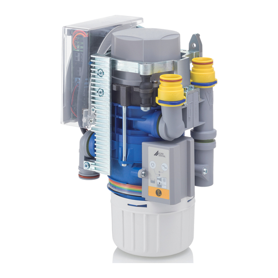
Product description Operation CAS 1 Fluid intake Vacuum, to suction unit Aspiration input Fluid output Motor Separation Separation rotor Centrifuge Light barriers (3x) 10 Sensor enclosure 11 Cone pump 12 Amalgam collector vessel 13 Float sensor 14 Fluids 15 Amalgam particles... -
Page 12: 5�1 Operation
Product description 5.1 Operation The spiral motion feeds the separated fluid con- tinuously to the pump wheel, which transports CAS 1 Combi-Separator the fluid into the collector vessel� The fluid is The task of the CAS 1 combi-separator is to transported to the centrifuge (8) via a pump provide continuous separation of secretions and cone (11)�... -
Page 13: Sediment Level Measurement
Product description As soon as no further fluid is fed to the amal- gam separator, e�g� when the suction hose is placed back in the hose manifold, the centrifuge drum is switched off after a short delay time� This switch-off brakes the motor, as a result of which the ring of water, which continues to rotate due to inertia, rinses the separated parti- cles out of the centrifuge (8) downwards into the... -
Page 14: Requirements
Installation Requirements 6.5 Information about electrical connections 6.1 Installation/setup room Ensure that electrical connections to the The room chosen for set up must fulfil the fol- mains power supply are carried out in accord- lowing requirements: ance with current valid national and local reg- –... -
Page 15: Installation
Installation Installation Control cable Installation type Line layout (minimum Prior to working on the device or in case requirements) of danger, disconnect it from the mains (e� g� pull the mains plug)� Fixed installation – Shielded sheathed cable (e�g� (N)YM (St)-J) 7.1 Combining devices safely Flexible –... -
Page 16: Installation Of The Cas 1 In
Installation 7.2 Installation of the CAS 1 in Inlet and outlet hoses Connect and attach the inlet and outlet hoses treatment units with DürrConnect connectors to the relevant connections on the unit�Route the hoses at an WARNING incline� Infection due to contaminated unit... -
Page 17: Electrical Connections, Controller
Installation 7.3 Electrical connections, Place selection valve Rinsing unit controller Suction unit relay (alternative) Power supply: Display panel, external – Safety transformer order number: 9000-150-46 7.4 Electrical connections – Safety transformer 24 V AC with a with an Station selection valve / safety valve isolator consisting of two means of patient Connect the station selection valve / safety protection (MOPP) between the mains circuit... -
Page 18: Commissioning And First Start-Up
Installation Commissioning and first start-up In many countries technical medical products and electrical devices are sub- ject to regular checks at set intervals� The owner must be instructed accordingly� Turn on the unit power switch or the main surgery switch� Carry out an electrical safety check in accord- ance with applicable local regulations (e�g�... -
Page 19: Service Program
Installation Service program 7117100018L30 1712V002... -
Page 20: Description Of The Service Program
Installation 10 Description of the service 10.3 Sediment level measurement program While the service program is activated, the safety check for the collector vessel Wear protective equipment to avoid any is deactivated� risk of infection (e�g� liquid-tight pro- The sediment level measurement can be used tective gloves, protective goggles, face to check the function of the sediment sensor mask)�... -
Page 21: Display/Handling
Operation 11 Display/handling 11.3 Amalgam collector vessel is 100% full Yellow LED is on Red display flashes Audible signal melody sounds – At a fill level of 100% the signal melody can no longer be switched off by pressing the reset button�... -
Page 22: En 11�5 Motor Fault
Operation 12 Disinfection and cleaning 11.5 Motor fault Red display and NOTICE green LED flash alternately Device malfunctions or damage due to use of incorrect media Audible signal Guarantee claims may become invalid as a result� – Press the reset button briefly to switch off the Do not use any foaming agents, e�g�... -
Page 23: 12�3 Once Or Twice A Week Before The Midday Break
Operation 13 Replace the amalgam 12.3 Once or twice a week before the midday break collector vessel Under harsher conditions (e�g� hard water or frequent use of prophylaxis powders) WARNING 1x daily before the midday break Risk of contamination if the amalgam collector vessel is reused since the The following are required for cleaning: collector vessel is not water-tight. -
Page 24: 13�1 Disposal Of The Collector Vessel
Operation 13.1 Disposal of the collector vessel Used amalgam collector vessels must not be sent in the post! Dürr Dental is not a waste management company and is not allowed by law to accept any filled amalgam collector ves- sels� Arrange to have filled amalgam collector vessels collected from the surgery by a local waste management company�... -
Page 25: Maintenance
Operation 14 Maintenance All maintenance work must be performed by a qualified expert or by one of our Service Tech- nicians� Prior to working on the device or in case of danger, disconnect it from the mains (e� g� pull the mains plug)�... -
Page 26: 14�1 Tests
Operation 14.1 Tests Work steps to be performed: Fill the test vessel with water and insert it into the unit� WARNING Infection due to contaminated unit Start the device and wait until it switches off again� Clean and disinfect the suction before working on the unit�... -
Page 27: Troubleshooting
Troubleshooting 15 Tips for operators and service technicians Any repairs above and beyond routine maintenance must only be carried out by suitably quali- fied personnel or by one of our service technicians� WARNING Infection due to contaminated unit Clean and disinfect the suction before working on the unit� Wear protective equipment when working (e� g�... - Page 28 Troubleshooting Fault Probable cause Solution Yellow display is on Amalgam collecting container is Change the amalgam collecting 95% full container� GREEN LED illuminates Audible signal melody Float sensor dirty or blocked If this display occurs repeatedly sounds even when the collecting con- tainer is empty, check that the float sensor can move freely�...
- Page 29 Troubleshooting Fault Probable cause Solution Increased vibration of the Pump cone dirty Clean or replace the pump device cone� * Centrifuge dirty Clean or replace the centrifuge� * Water supply too low Introduce water into the suction pipe� Retrofit the rinsing unit� * Check the rinsing unit for its correct installation position�...
-
Page 30: Transporting The Unit
Dürr Dental� Disinfect a defective unit using a suitable sur- face disinfection agent� Seal all connections with sealing caps� Pack the unit securely in preparation for trans- port� 16.1 Close CAS 1 Dummy bushing Ring clamp 7117100018L30 1712V002... -
Page 31: Appendix
Appendix 17 Information about EMC in accordance with EN 60601-1-2 17.1 General information The information in this leaflet includes excerpts from the relevant European standards for electrical, medical devices� It must be observed when installing Dürr Dental devices or combining them with products of other manufacturers�... - Page 32 Appendix Resistance to electromagnetic interference (immunity) for all devices and systems The device is designed for use in electromagnetic environments specified below� The customer or operator of the device should ensure that the device is operated such an environment� Interference immu- IEC 60601 - test Compliance level Electromagnetic environment...
- Page 33 Appendix Electromagnetic interference immunity for devices or systems that are not life-sustaining Portable and mobile communication devices should not be used any closer to the unit (including cables) than the recommended safety distance, which is calculated based on the applicable formula for the transmission frequency�...
- Page 34 Appendix Recommended safety distance between portable and mobile HF communication devices and the unit The device is designed for use in the electromagnetic environments specified below, in which the HF disturbance variables are controlled� The customer or the operator of the device can help to prevent electromagnetic interference by maintaining the minimum distances between mobile HF communica- tion equipment (transmitters) and the device as recommended below in accordance with the maxi- mum output line of the communication equipment�...
- Page 36 Hersteller/Manufacturer: DÜRR DENTAL SE Höpfigheimer Str. 17 74321 Bietigheim-Bissingen Germany Fon: +49 7142 705-0 www.duerrdental.com info@duerrdental.com...
Need help?
Do you have a question about the CAS 1 and is the answer not in the manual?
Questions and answers