
Related Manuals for Durr Dental PTS 120


Summary of Contents for Durr Dental PTS 120
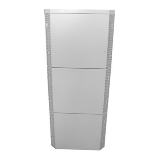
- Page 1 Dürr Dental PTS 120 Installation and Operating Instructions 9000-619-15/30 ...
-
Page 3: Table Of Contents
4. Technical Data � � � � � � � � � � � � � � � � � � � 7 16�1 Dry suction units V 300 S, 4�1 PTS 120 � � � � � � � � � � � � � � � � � � � � � � 7 Condensate separator, 4�2 Ambient conditions �... -
Page 4: Important Information
1.4 Correct Usage accessories� The PTS 120 has been specially designed to • Dürr Dental are only responsible for the equip- provide compressed air, vacuum and amalgam ment with regard to safety, reliability and pro-... -
Page 5: 1�5 Incorrect Usage
In spite of this, we feel it is our duty to mention the following safety measures in order to pre- Do not operate the PTS 120 in vent any possible danger� rooms where operations are carried •... -
Page 6: Warnings And Symbols
3. Warnings and Symbols In the operating instructions the following war- nings and symbols have been used: Information and/or mandatory re- gulations or prohibitions for the prevention of personal injury or sub- stantial property damage Special information regarding economi- cal use of the appliance or other information�... -
Page 7: Technical Data
4. Technical Data 4.1 PTS 120 Model 0950-120 /02, /03 /12, /13 Voltage 230 / 1~ 230 / 1~ 230 / 1~ Electrical frequency 50/60** 50/60** Weight Electric power max 1�72 Current consumption max 10�4 Protection class Fuse type IP20... -
Page 8: Functional Description
Installation and Operating Instructions supplied with the appropriate appliance� The illustration shows only one of the many ways in which the PTS 120 range can be set up� 5.1 Compressor generator (A) The pressure switch serves to switch the com- pressor unit automatically on and off�... -
Page 9: Mounting
Replace the exhaust air bacteria filter af- The PTS 120 is delivered in various parts for re- ter 1-2 years at the latest according to asons of weight and transportation and is sent its condition in transport boxes to the factory�... -
Page 10: 7�2 Setting Up The Pts
PTS to any side object (e�g� cupboard)� 10 °C - 40 °C 7.3 Remove transportation safety devices Remove the upper cover (6) of the PTS 120 and remove the packing protection (8) to the com- pressor unit, see figs� 7 and 8� 7.4 Electrical connection Safety for the electrical connection •... -
Page 11: Connecting Compressed Air Supply To Tank
8. Connecting compressed air supply to tank (treatment unit) • Feed the compressed air hoseØ8x3x14 through the cable ducts (31 and 32) of the PTS and secure them to the connection noz- zles (30) of the tank with hose clamps, see figs�... -
Page 12: Installing V 300 S Condensate
9. Installing V 300 S condensate separator Where the PTS 120 is not fitted with a condensate separator (conversion set 0950-500-52) then proceed to section "10� Set up and connection of dry suction unit"� • Screw the condensate separator (42) to the... -
Page 13: 10�1 V 300 S
10.1 V 300 S Placing V 300 S in PTS 120 • Place the V 300 S into the PTS� • Guide the suction and exhaust air hoses through the openings (32) of the PTS, see fig� 11�... -
Page 14: Suction Units
• The connection cable of the suction machine must not touch any hot surfaces� Where the PTS 120 is fitted with an amalgam separator (CA 1) then the sur- ge tank together with plumbing must be installed before installation of the VS units, proceed to section "12�1 Installa-... -
Page 15: 11�2 Vsa 300 S
11.2 VSA 300 S VSA 300 S electrical connections • Guide the mains cable () supplied through the openings on the VSA 300 S terminal box and secure to connector X8 (77)� • Clamp the bridge contact (76) to terminal X2, 1 and 3�... -
Page 16: 12�1 Install Surge Tank
DürrConnect ventilation and connection pieces� • Screw the surge tank into position on the mounting bracket and into the PTS 120 (54)� • Connect the waste water intake (56) between the VS 300 S and surge tank� • Guide the suction hose (55) from behind through the hose openings (32) of the PTS 120, see fig�... -
Page 17: Installing Amalgam Separator
12.2 Installing Amalgam Separator CA 1 • Clip the DürrConnect ventilation valve unit for CA 1 together (60) and screw in place on mounting plate (61)� • Connect the ventilation valve and elbow piece (62) together using a transparent piece of hose�... - Page 18 • First place the mounting plate (61) into the PTS 120 and screw down, then fix the CA 1 onto the mounting plate (63), see figs� 26 and 27� • Connect the CA 1 (64) to the existing building waste water system�...
-
Page 19: 12�3 Amalgam Separator Ca
(71) X1 of the amalgam se- parator CA 1� Guide the two-wire cable through the cable openings of the PTS 120 and connect to the transformer unit (70) at 24 V output connection� • Connect the two-pin cable (N, L) to the 230 V input side of the transformer unit and to the PTS 120 PCB (main board) (74) terminal X7�... -
Page 20: Pts 120 Electrical Connections
13. PTS 120 electrical connections The mains power supply must be carried out using an earthed safety contact and should be connected via the main power switch of the treatment unit or via the main surgery switch� The supply lines to the unit must be laid without mechanical strain. -
Page 21: Finishing Touches
The compressor generator will start and swit- ches off on reaching c� 7�5 bar� • Switch on the suction machine by removing the suction hose� • Close the three noise-reducing panels to the PTS 120 again, see figs� 37 and 38� 2015/01/26... -
Page 22: Circuit Diagram For 230 V 1~ 50Hz
15. Circuit diagram for 230 V 1~ 2015/01/26... -
Page 23: Peripherals Connection Plan
16. Peripherals connection plan 16.1 Dry suction units V 300 S, Condensate separator, Compressor Tornado 1, drying units PTS 120 Tornado 1 Treatment place Compressed air Ø 8x3x14 V 300 S Exhaust air Suction air 2015/01/26... -
Page 24: 16�2 Wet Suction Units Vs 300 S, Com- Pressor Tornado 1, Drying Units
16.2 Wet suction units VS 300 S, compressor Tornado 1, drying units PTS 120 Tornado 1 Treatment place Compressed air Ø 8x3x14 VS 300 S or VSA 300 S Exhaust air Suction air 2015/01/26... -
Page 25: Amalgam Separator Ca 1
16.3 Wet suction units VS 300 S, amalgam separator CA 1 PTS 120 Treatment place VS 300 S Exhaust CA 1 Suction 2015/01/26... - Page 26 2015/01/26...
- Page 28 DÜRR DENTAL SE Höpfigheimer Str. 17 74321 Bietigheim-Bissingen Germany Fon: +49 7142 705-0 www.duerrdental.com info@duerrdental.com...
Need help?
Do you have a question about the PTS 120 and is the answer not in the manual?
Questions and answers