
Related Manuals for Avaya S8800


Summary of Contents for Avaya S8800
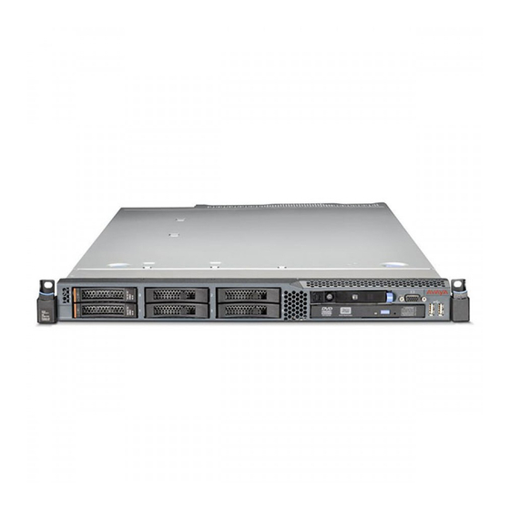
- Page 1 Maintaining the Avaya S8800 Server for ® Avaya Aura Communication Manager Release 6.2 03-603446 Issue 3 July 2012...
- Page 2 Avaya does not guarantee that these links will work all the time and has no control over the availability of the linked pages.
-
Page 3: Table Of Contents
Contents Chapter 1: Introduction...................... Support..............................5 Chapter 2: Replace the Avaya S8800 Server and its components......... Safety information............................. 7 General safety information....................... 7 Safety Inspection..........................8 Electrical safety rules........................9 Protecting against ESD damage...................... 10 Material codes for replaceable components..................... 11 Replace the Avaya S8800 Server...................... - Page 4 ® Maintaining the Avaya S8800 Server for Avaya Aura Communication Manager July 2012...
-
Page 5: Chapter 1: Introduction
Chapter 1: Introduction This document describes the maintenance procedures for the Communication Manager S8800 1U Server with a simplex and duplex configuration. The document has two main sections: • Replace the Avaya S8800 Server and its components • Troubleshoot the Avaya S8800 Server The document does not provide information about the Communication Manager commands and server alarms. - Page 6 Introduction ® Maintaining the Avaya S8800 Server for Avaya Aura Communication Manager July 2012 Comments? infodev@avaya.com...
-
Page 7: Chapter 2: Replace The Avaya S8800 Server And Its Components
Avaya S8800 Server with a duplex configuration. However, if you are replacing the Avaya S8800 Server with a duplex configuration, make sure that the good server is in the active mode and the defective server is in the stand by mode. If necessary, interchange the servers. For more information, see Interchanging and busying out the server on page 12. -
Page 8: Safety Inspection
Replace the Avaya S8800 Server and its components • Do not perform any action that causes hazards to the customer or that makes the equipment unsafe. • Before you start the system unit, ensure that other technical support staff and customer personnel are not in a hazardous position. -
Page 9: Electrical Safety Rules
Obtain the mats locally, if necessary. - When using testers, set the controls correctly and use the approved probe leads and accessories for the tester. ® Maintaining the Avaya S8800 Server for Avaya Aura Communication Manager July 2012... -
Page 10: Protecting Against Esd Damage
Replace the Avaya S8800 Server and its components - Use only one hand when working with powered-on electrical equipment. Keep the other hand in your pocket or behind your back. This precaution can prevent current from passing through your body. -
Page 11: Material Codes For Replaceable Components
2GB DIMMs 1333 Mhz 700478274 146 GB SAS 2.5” 10K RPM hard disk drive 700478316 2-port Ethernet card (PCIe card) 700478290 675 watt power supply 700478308 RAID battery 700478753 ® Maintaining the Avaya S8800 Server for Avaya Aura Communication Manager July 2012... -
Page 12: Replace The Avaya S8800 Server
About this task Important: You must interchange and busy out the server only if you are replacing the Avaya S8800 Server with a duplex configuration. If you are replacing the Avaya S8800 Server with a simplex configuration, skip this task. -
Page 13: Tasks To Replace An Avaya S8800 Server
Disconnect all power Important: cords and external cables. Be sure to label the cables for easy reconnecting. ® Maintaining the Avaya S8800 Server for Avaya Aura Communication Manager July 2012... -
Page 14: Removing The Server From The Rack
Replace the Avaya S8800 Server and its components Task Description Notes Remove the server Removing the from the rack. server from the rack on page 14. Remove the reusable Reuse of components from the hardware components failed server. in replacement... -
Page 15: Installing The Server In The Rack
5. Make sure that the front latch slides over the nail heads. See 5 in Figure 6. Lift the locking levers on the slide rails. See 6 in Figure ® Maintaining the Avaya S8800 Server for Avaya Aura Communication Manager July 2012... -
Page 16: Turning On The Server
Replace the Avaya S8800 Server and its components 7. Push the server all the way into the rack until it clicks into place. See 7 in Figure 8. Insert the optional M6 screws in the front of the server when you move the rack cabinet or if you install the rack cabinet in a vibration-prone area. -
Page 17: Testing The System Using The System Management Interface
6. From a computer on the customer LAN, use Internet Explorer to connect to the server. 7. Log in as craft. ® Maintaining the Avaya S8800 Server for Avaya Aura Communication Manager July 2012... -
Page 18: Returning Defective Equipment
Returning defective equipment Procedure 1. Place the defective equipment in the protective packaging that accompanied the replacement equipment. 2. Return the defective equipment to Avaya using the procedures established for your region. Replace the hardware components Removing and installing the server cover... - Page 19 Always use an electrostatic-discharge wrist strap or other grounding system when you work inside the server. For more information, see Protecting against ESD damage on page 10. ® Maintaining the Avaya S8800 Server for Avaya Aura Communication Manager July 2012...
- Page 20 Replace the Avaya S8800 Server and its components Procedure 1. Make sure that all internal cables, PCIe cards, and other components are installed and seated correctly and that you have not left loose tools or parts inside the server. Also, make sure that all internal cables are correctly routed.
-
Page 21: Replacing Memory Modules
Dual microprocessors require equal distribution of DIMMs between the processors. For example, a 12GB DIMM would have connectors 3,6,8 and 11,14,16 populated. The following figure shows the numbering sequence of the DIMMs. ® Maintaining the Avaya S8800 Server for Avaya Aura Communication Manager July 2012... - Page 22 Replace the Avaya S8800 Server and its components DIMMs for microprocessor 2 DIMMs for microprocessor 1 Back of server Front of server Removing the DIMM air baffle About this task You must remove the DIMM air baffle to replace or install a memory module.
- Page 23 Protecting against ESD damage on page 10. Procedure Carefully open the retaining clips on each end of the memory module connector and remove the memory module. See the following figure. ® Maintaining the Avaya S8800 Server for Avaya Aura Communication Manager July 2012...
- Page 24 Replace the Avaya S8800 Server and its components Important: Open and close the clips gently to avoid breaking the retaining clips or damaging the memory module connectors. Memory module Retaining clip When you install or remove memory modules, the server configuration information changes.
- Page 25 If there is a gap between the memory module and the retaining clips, the memory module has not been correctly inserted. Open the retaining clips, remove the memory module, and then reinsert it. ® Maintaining the Avaya S8800 Server for Avaya Aura Communication Manager July 2012...
- Page 26 Replace the Avaya S8800 Server and its components 7. Replace the air baffle over the memory modules. Make sure all cables are out of the way. 8. Install the cover. 9. Reconnect the external cables and power cords. 10. Turn on the attached devices and the server.
-
Page 27: Removing And Installing A Pci Riser-Card Assembly
Removing and installing a PCI riser-card assembly Removing a PCI riser-card assembly About this task You must remove the PCI riser-card assembly to replace the PCIe card. ® Maintaining the Avaya S8800 Server for Avaya Aura Communication Manager July 2012... - Page 28 Replace the Avaya S8800 Server and its components Important: Always use an electrostatic-discharge wrist strap or other grounding system when you work inside the server. For more information, see Protecting against ESD damage on page 10. Procedure 1. Turn off the server and all attached devices.
- Page 29 Protecting against ESD damage on page 10. Procedure 1. Align the PCI riser-card assembly with the PCI connector on the system board. See the following figure. PCI riser connector 2 ® Maintaining the Avaya S8800 Server for Avaya Aura Communication Manager July 2012...
-
Page 30: Replacing A Pcie Card
Replace the Avaya S8800 Server and its components PCI riser-card assembly (full-height, half-length PCIe cards) PCI riser-card assembly (low profile PCIe cards) PCI riser connector 1 2. Press down on the riser-card assembly. Make sure that the assembly is fully seated in the riser-card connector on the system board. - Page 31 When you install a PCIe card, make sure that the card is correctly seated in the riser-card assembly and that the riser-card assembly is securely seated in the riser-card connector on ® Maintaining the Avaya S8800 Server for Avaya Aura Communication Manager July 2012...
- Page 32 Replace the Avaya S8800 Server and its components the system board before you turn on the server. An incorrectly seated PCIe card might cause damage to the system board, the riser-card assembly, or the PCIe card. Important: Always use an electrostatic-discharge wrist strap or other grounding system when you work inside the server.
-
Page 33: Replacing A Hard Disk Drive
10. Procedure 1. Slide the release latch (orange) gently to the left to unlock the drive handle. See the following figure. Drive tray assembly Drive handle ® Maintaining the Avaya S8800 Server for Avaya Aura Communication Manager July 2012... - Page 34 Replace the Avaya S8800 Server and its components 2. Grasp the handle and slide the drive out of the drive bay approximately 25 mm (1 inch). Wait until the drive stops spinning before you remove the drive completely from the bay.
- Page 35 1. On the SMI, click Server Configuration > Display Configuration. 2. On the Display Configuration page, verify that Disk devices shows the details of two hard drives. ® Maintaining the Avaya S8800 Server for Avaya Aura Communication Manager July 2012...
-
Page 36: Replacing A Power Supply
Replace the Avaya S8800 Server and its components Verify RAID status: 1. On the SMI, click Diagnostics > RAID Status. 2. On the RAID Status page, verify that the status of the two hard drives is reported. To do so: •... - Page 37 3. Press and hold the orange release tab to the left. See the following figure. ® Maintaining the Avaya S8800 Server for Avaya Aura Communication Manager July 2012...
- Page 38 Replace the Avaya S8800 Server and its components Power supply release tab Power supply filler Power supply 4. Pull the power supply part of the way out of the bay, and then release the latch and support the power supply as you pull the power supply the rest of the way out of the bay.
- Page 39 8. Make sure that both the AC LED and the DC LED on the power supply light up. Both LEDs light up when the power supply is operating correctly. ® Maintaining the Avaya S8800 Server for Avaya Aura Communication Manager July 2012...
-
Page 40: Replacing The Raid Battery
Replace the Avaya S8800 Server and its components Replacing the RAID battery Removing the RAID battery Before you begin The RAID battery is located on top of the RAID controller card. The RAID configuration data is preserved when you replace the battery. - Page 41 See the following figure. Battery Battery carrier 3. Install the cover. 4. Reconnect the external cables and power cords. 5. Turn on the attached devices and the server. ® Maintaining the Avaya S8800 Server for Avaya Aura Communication Manager July 2012...
-
Page 42: Replacing The Usb Modem
Perform this task only if you are using a USB modem to report alarms. If you are using SAL to report alarms, skip this task. Avaya recommends to use SAL to report alarms. In using a modem to report alarms, it is not possible to achieve 99.99% availability on an S8800 server in simplex mode since it cannot detect and report when the server is down. -
Page 43: Returning Defective Equipment
Returning defective equipment Procedure 1. Place the defective equipment in the protective packaging that accompanied the replacement equipment. 2. Return the defective equipment to Avaya using the procedures established for your region. ® Maintaining the Avaya S8800 Server for Avaya Aura... - Page 44 Replace the Avaya S8800 Server and its components ® Maintaining the Avaya S8800 Server for Avaya Aura Communication Manager July 2012 Comments? infodev@avaya.com...
-
Page 45: Chapter 3: Troubleshoot The Avaya S8800 Server
LEDs, do not run the server continuously with the light path diagnostics panel outside of the server. The panel should be outside of the server for only a short ® Maintaining the Avaya S8800 Server for Avaya Aura Communication Manager July 2012... - Page 46 • 2-port Ethernet card (PCIe card) • RAID battery 8. Check for successful completion of power-on self-test (POST). POST error messages are displayed on the system monitor. ® Maintaining the Avaya S8800 Server for Avaya Aura Communication Manager July 2012 Comments? infodev@avaya.com...
-
Page 47: Hard Disk Drive Leds
Make sure that the drive assembly connects to the hard disk drive backplane. 3. Check the green activity LED and the amber status LED for the hard disk drive: ® Maintaining the Avaya S8800 Server for Avaya Aura Communication Manager July 2012... - Page 48 1. Make sure that the hard disk drive is recognized by the RAID controller card (the green hard disk drive activity LED is flashing). 2. Check the amber status LED for the hard disk drive. ® Maintaining the Avaya S8800 Server for Avaya Aura Communication Manager July 2012 Comments? infodev@avaya.com...
-
Page 49: Troubleshooting Power Problems
(three flashes per second), the server will not turn on. Troubleshooting steps Procedure 1. Disconnect the server power cords. 2. Connect a customer-provided keyboard, mouse, and monitor to the server. ® Maintaining the Avaya S8800 Server for Avaya Aura Communication Manager July 2012... - Page 50 Restart the server after reinstalling each PCI riser card. 3. If the Channel D power LED lights up: a. Remove all DIMMs and restart the server. ® Maintaining the Avaya S8800 Server for Avaya Aura Communication Manager July 2012 Comments? infodev@avaya.com...
-
Page 51: Troubleshooting Memory Problems
• If you changed the memory, you updated the memory configuration in the Setup utility. 2. Shut down the server and remove the power cords. 3. Reseat the DIMMs. ® Maintaining the Avaya S8800 Server for Avaya Aura Communication Manager July 2012... - Page 52 7. Replace the failed DIMM. Repeat steps 5 and 6 until you have tested all removed DIMMs. 8. Replace the lowest numbered DIMM pair of those identified. Then, restart the server. 9. Repeat Step 8 as necessary. ® Maintaining the Avaya S8800 Server for Avaya Aura Communication Manager July 2012 Comments? infodev@avaya.com...
-
Page 53: Power Supply Leds
No AC power to the server or a problem with the AC power source. This is a normal condition when no AC power is present. Server has no AC power on page 54 ® Maintaining the Avaya S8800 Server for Avaya Aura Communication Manager July 2012... -
Page 54: Troubleshooting Power Supply Problems
2. Make sure that the power cord is connected to a functioning power source. 3. Turn the server off and then turn the server back on. 4. Replace the power supply. ® Maintaining the Avaya S8800 Server for Avaya Aura Communication Manager July 2012 Comments? infodev@avaya.com... - Page 55 Faulty power supply Several LEDs and combinations of LEDs can indicate that a power supply is faulty. The following table describes these LEDs and LED combinations. Error ® Maintaining the Avaya S8800 Server for Avaya Aura Communication Manager July 2012...
-
Page 56: Troubleshooting Light Path Diagnostic Leds
Troubleshooting steps Procedure 1. If any replaceable components need to be replaced, replace them. 2. If a faulty component is not replaceable, replace the server. ® Maintaining the Avaya S8800 Server for Avaya Aura Communication Manager July 2012 Comments? infodev@avaya.com... - Page 57 PCI bus. Restart the server after each card is removed. 4. Reseat the failing PCIe card. ® Maintaining the Avaya S8800 Server for Avaya Aura Communication Manager July 2012...
- Page 58 1. Make sure that the room temperature is not too high. 2. Make sure that the air vents are not blocked. 3. Determine whether a fan has failed. If it has, replace the server. ® Maintaining the Avaya S8800 Server for Avaya Aura Communication Manager July 2012 Comments? infodev@avaya.com...
- Page 59 1. If you have a monitor, check the system event log for information about the error. 2. Shut down the server and remove the power cord. 3. Check that all plug-in cards and devices are firmly installed. 4. Turn on the server. ® Maintaining the Avaya S8800 Server for Avaya Aura Communication Manager July 2012...
- Page 60 Setup utility and select System Information > System Summary > Processor Details. VRM LED lights up The VRM LED on the light path diagnostics panel is not used. ® Maintaining the Avaya S8800 Server for Avaya Aura Communication Manager July 2012 Comments? infodev@avaya.com...
- Page 61 BRD LED lights up The BRD LED on the light path diagnostics panel lights up when an error occurs on the system board. Troubleshooting steps Procedure Replace the server. ® Maintaining the Avaya S8800 Server for Avaya Aura Communication Manager July 2012...
- Page 62 Troubleshoot the Avaya S8800 Server ® Maintaining the Avaya S8800 Server for Avaya Aura Communication Manager July 2012 Comments? infodev@avaya.com...
-
Page 63: Index
................. hard disk drive ........... installing ............... NMI LED ..............LEDs ..............notices, legal ..............removing .............. troubleshooting ..........hard drive ..............OVERSPEC LED ............installation ..............® Maintaining the Avaya S8800 Server for Avaya Aura Communication Manager July 2012... - Page 64 ............removing .............. RAID LED ..............replace ................. USB modem ............... replacing server ............ required equipment and tools ......reusing components ..........VRM LED ..............® Maintaining the Avaya S8800 Server for Avaya Aura Communication Manager July 2012...
Need help?
Do you have a question about the S8800 and is the answer not in the manual?
Questions and answers