
Related Manuals for Avaya S8800


Summary of Contents for Avaya S8800
- Page 1 Installing the Avaya S8800 Server for ™ Avaya Aura Communication Manager Release 6.0 03-603444 June 2010...
- Page 2 Avaya does not guarantee that these links will work all the time and has no control over the availability of the linked pages.
-
Page 3: Table Of Contents
Connecting for duplication reliability using software memory duplication..........35 Chapter 4: Troubleshooting equipment................37 Troubleshooting the hardware installation.......................37 Avaya and customer equipment is missing....................37 The server has no power........................37 Index............................39 ™ Installing the Avaya S8800 Server for Avaya Aura Communication Manager June 2010... - Page 4 ™ Installing the Avaya S8800 Server for Avaya Aura Communication Manager June 2010...
-
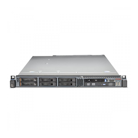
Page 5: Chapter 1: Overview Of Server And Components
Communication Manager supports the 1U model of the S8800 Server. While installing Communication Manager in simplex mode on the S8800 Server, you only use 1 S8800 Server, whereas, installing Communication Manager in duplex mode requires you to have 2 S8800 Servers. - Page 6 DVD eject button DVD drive activity LED DVD drive Drive bay 5 (Unused for Communication Manager) Drive bay 3 (Unused for Communication Manager) Drive bay 1 Rack release latch ™ Installing the Avaya S8800 Server for Avaya Aura Communication Manager June 2010...
-
Page 7: Back Of Server
Power supply error LED (amber) Power supply 2 (optional redundant power supply) Power supply 1 (primary power supply) USB connector 3 Serial connector System error LED (amber) System locator LED (blue) ™ Installing the Avaya S8800 Server for Avaya Aura Communication Manager June 2010... -
Page 8: Server Specifications
Electrical input • Sine-wave input (47 - 63 Hz) required requirements • Input voltage low range: - Minimum: 100 V AC ™ Installing the Avaya S8800 Server for Avaya Aura Communication Manager June 2010... -
Page 9: Server Components
S8330D — 8GB DRAM Media drive DVD-R/W SATA slimline No additional options Hard disk drive expansion bays Six 2.5-inch hot-swap No additional options SAS hard disk drive bays ™ Installing the Avaya S8800 Server for Avaya Aura Communication Manager June 2010... - Page 10 November 2009. S8300D Server — Single 250GB drive RAID controllers ServeRAID-MR10i RAID No additional options SAS adapter that provides RAID level 1 or 5. Includes 256 MB cache ™ Installing the Avaya S8800 Server for Avaya Aura Communication Manager June 2010...
- Page 11 75 Hz. • SVGA compatible video controller • DDR2 250 MHz SDRAM video memory controller • Avocent Digital Video Compression • Video memory is not expandable ™ Installing the Avaya S8800 Server for Avaya Aura Communication Manager June 2010...
-
Page 12: Environmental Requirements
914.4 m to 2,133 m (3,000 to 7,000 feet) Server off 10°C to 43°C (50.0°F to 2,133 m 8% to 80% 109.4°F) (7,000 feet) ™ Installing the Avaya S8800 Server for Avaya Aura Communication Manager June 2010... -
Page 13: Chapter 2: Server Rack Installation
• Do not overload the AC supply branch circuit that provides power to the rack. The total rack load should not exceed 80 percent of the branch circuit rating. ™ Installing the Avaya S8800 Server for Avaya Aura Communication Manager June 2010... -
Page 14: Avaya-Provided Equipment
The customer must provide the following equipment: • Standard 19-inch four-post equipment rack that is properly installed and solidly secured. The rack must meet the following standards: ™ Installing the Avaya S8800 Server for Avaya Aura Communication Manager June 2010... -
Page 15: Clearance Requirements
Verify that the rack is installed according to the manufacturer's instructions and in accordance with all local codes and laws. ™ Installing the Avaya S8800 Server for Avaya Aura Communication Manager June 2010... -
Page 16: Installing The Avaya S8800 Server
Troubleshoot the installation. Installing the Avaya S8800 Server Rack installation components The following figure shows the items that you need to install the server in the rack cabinet. ™ Installing the Avaya S8800 Server for Avaya Aura Communication Manager June 2010... -
Page 17: Attaching The Rails To The Rack
If the slide rails in your rack installation kit came with thumbscrews installed, remove them before you begin the following installation procedure. Each slide rail is marked with either an R (right) or an L (left). ™ Installing the Avaya S8800 Server for Avaya Aura Communication Manager June 2010... - Page 18 The slide rails that come with the server are compatible with standard 19-inch, 4-post racks that have square holes. If you are installing the server in any other type of rack, Avaya requires that the customer provide the appropriate rails or shelf for their rack. Rack Solutions has numerous rail kits and shelf options.
-
Page 19: Installing The Server In The Rack
Installing the server in the rack Prerequisites Attach rails to the rack. 1. Pull the slide rails forward (1) until they click, two times, into place. See the following figure. ™ Installing the Avaya S8800 Server for Avaya Aura Communication Manager June 2010... - Page 20 8. Insert the optional M6 screws (8) in the front of the server when you move the rack cabinet or if you install the rack cabinet in a vibration-prone area. See the following figure. ™ Installing the Avaya S8800 Server for Avaya Aura Communication Manager June 2010...
-
Page 21: Installing The Cable Management Arm
1. Connect one end of the support arm (1) to the same slide rail to which you plan to attach the cable-management arm so that you can swing the other end of the support arm (2) toward the rack. See the following figure. ™ Installing the Avaya S8800 Server for Avaya Aura Communication Manager June 2010... - Page 22 4. To attach the other side of the support arm to the backside of the slide rail, pull the pin out (5), and then slide the bracket (6) into the slide rail. See the following figure. ™ Installing the Avaya S8800 Server for Avaya Aura Communication Manager June 2010...
- Page 23 13. Route the cables and power cords on the cable-management arm (13) and secure them with cable ties or hook-and-loop fasteners. See the following figure. ™ Installing the Avaya S8800 Server for Avaya Aura Communication Manager June 2010...
-
Page 24: Turning On The Server
After the server is installed in the rack, turn it on to make sure that it works. Once you determine that it works, turn it off before you start any software installation procedure. ™ Installing the Avaya S8800 Server for Avaya Aura Communication Manager June 2010... - Page 25 The power-on LED will stop blinking and stay lit. After you press the power button, the server takes approximately 5 minutes to initialize. Next steps See the specific product documentation for information on installing the operating system and software. ™ Installing the Avaya S8800 Server for Avaya Aura Communication Manager June 2010...
- Page 26 Server rack installation ™ Installing the Avaya S8800 Server for Avaya Aura Communication Manager June 2010...
-
Page 27: Chapter 3: Installing And Connecting Peripheral Equipment
• USB modem as an optional method to report alarms for the Communication Manager and the server. Note: Avaya recommends the use of SAL to provide remote access and alarm reporting for Communication Manager. • Laptop for initial administration on the server. -
Page 28: Installing The Ethernet Switch
Installing and connecting peripheral equipment 1. Place the UPS at the bottom of rack. 2. Connect one end of power-cord connector of the S8800 Server power supply to the UPS. 3. Connect the power cord of the UPS to a properly grounded electrical outlet. - Page 29 Ethernet Connector Connecto 1 for r 1 for redundan redundan Ethernet Not Used Not Used Not Used Not Used Not Used Located on the Dual board ™ Installing the Avaya S8800 Server for Avaya Aura Communication Manager June 2010...
-
Page 30: Sal Gateway Installation
Use standard CAT5 cables with RJ–45 connectors on each end to connect the server, Ethernet switch, and port network (if there is any). The S8800 Server can be connected to H.248 gateways as well as port networks. 1. Connect the Ethernet connector 1 to the Ethernet switch (customer LAN / processor Ethernet 2. -
Page 31: Connecting The Usb Card Reader
2. Insert the compact flash card in the card reader. Note: You can hot swap the USB card reader. The USB card reader uses a 128 MB or higher capacity flash card to back up data. ™ Installing the Avaya S8800 Server for Avaya Aura Communication Manager June 2010... -
Page 32: Connecting Laptop For Initial Administration
Use standard CAT5 cables with RJ45 connectors on each end to connect to the various ports. The S8800 server has 4 Ethernet ports (2 ports on the motherboard and 2 on the Dual NIC card) and a dedicated Ethernet port for the System management Ethernet connector (IMM) (also known as Baseboard Management Controller, BMC). -
Page 33: Connecting The Cables For Software Memory Duplication
Non-dedicated network Connecting the cables for software memory duplication The S8800 server in duplex mode can only use software memory duplication as the duplication method. Ethernet connector 4 (eth 3) is the dedicated NIC port that is used for duplicated configuration. - Page 34 No need to connect cable for memory duplication (only software memory duplication supported) Note: After physical installation and connectivity of the S8800 Server and peripheral equipment ™ for Communication Manager, refer to Installing and Configuring Avaya Aura Communication Manager Release 6.0 for installing and configuring Communication Manager on the S8800 Server.
-
Page 35: Connecting For Duplication Reliability Using Software Memory Duplication
Bridged network interface (Two physical ports are bonded to form a bridge. The virtual NIC provides network redundancy and helps in better network performance) System management Ethernet connector (IMM) ™ Installing the Avaya S8800 Server for Avaya Aura Communication Manager June 2010... - Page 36 Installing and connecting peripheral equipment ™ Installing the Avaya S8800 Server for Avaya Aura Communication Manager June 2010...
-
Page 37: Chapter 4: Troubleshooting Equipment
Turning on the server on page • Check the power supply LEDs on the back of the server. During normal operation, the AC LED and DC LED are both lit. ™ Installing the Avaya S8800 Server for Avaya Aura Communication Manager June 2010... - Page 38 Troubleshooting equipment ™ Installing the Avaya S8800 Server for Avaya Aura Communication Manager June 2010...
-
Page 39: Index
..............rack humidity requirements ..........attaching rails ............installing server ............ RAID controller specifications ............rails Install SAL gateway ............ attaching to rack ........... installation checklist ™ Installing the Avaya S8800 Server for Avaya Aura Communication Manager June 2010... - Page 40 ............... components ............USB card reader ............dimensions ............. installing in rack ........... specifications ............turning on ............. video controller weight ..............specifications ............temperature requirements .......... ™ Installing the Avaya S8800 Server for Avaya Aura Communication Manager June 2010...
Need help?
Do you have a question about the S8800 and is the answer not in the manual?
Questions and answers