Sign In
Upload
Manuals
Brands
WAGO Manuals
Control Unit
750-469/040-000
WAGO 750-469/040-000 Manuals
Manuals and User Guides for WAGO 750-469/040-000. We have
1
WAGO 750-469/040-000 manual available for free PDF download: Manual
WAGO 750-469/040-000 Manual (64 pages)
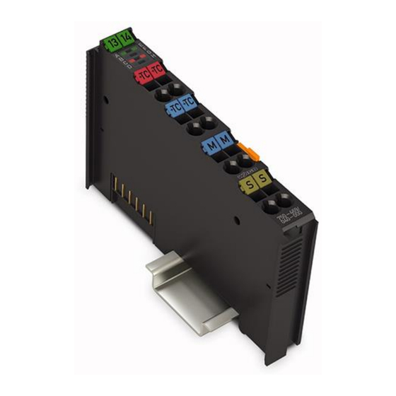
2AI Thermocouple configurable /XTR 2-Channel Analog Input Module for Thermocouples, Configurable /XTR For WAGO-I/O-SYSTEM 750 XTR
Brand:
WAGO
| Category:
Control Unit
| Size: 1 MB
Table of Contents
Table of Contents
3
Notes about this Documentation
5
Validity of this Documentation
5
Copyright
5
Symbols
6
Number Notation
8
Font Conventions
8
Table 1: Number Notation
8
Table 2: Font Conventions
8
Important Notes
9
Legal Bases
9
Subject to Changes
9
Personnel Qualifications
9
Use of the 750 Series in Compliance with Underlying Provisions
9
Technical Condition of Specified Devices
10
Disposal
10
2.1.4.1.1 Electrical and Electronic Equipment
10
2.1.4.1.2 Packaging
11
Safety Advice (Precautions)
12
Device Description
15
View
17
Figure 1: View
17
Table 3: Legend for Figure "View
17
Connectors
18
Data Contacts/Local Bus
18
Figure 2: Data Contacts
18
Power Jumper Contacts/Field Supply
19
Cage Clamp
19
Connectors
19
Figure 3: CAGE CLAMP
19
Table 4: Legend for Figure "CAGE CLAMP
19
Display Elements
21
Figure 4: Display Elements
21
Table 5: Legend for Figure "Display Elements
21
Operating Elements
22
Schematic Diagram
22
Figure 5: Schematic Diagram
22
Technical Data
23
Device Data
23
Supply
23
Communication
23
Table 6: Technical Data - Device
23
Table 7: Technical Data - Supply
23
Table 8: Technical Data - Communication
23
Inputs
24
Connection Type
24
Table 9: Technical Data - Inputs
24
Table 10: Technical Data - Field Wiring
24
Table 11: Technical Data - Power Jumper Contacts
24
Table 12: Technical Data - Data Contacts
24
Mechanical Conditions
25
Climatic Environmental Conditions
25
Table 13: Technical Data - Mechanical Conditions
25
Table 14: Technical Data - Climatic Environmental Conditions
25
Approvals
26
Standards and Guidelines
27
Table 15: Standards and Rated Conditions for Explosion Protection Applications
27
Table 16: Climatic and Mechanical Environmental Conditions and Shipbuilding
28
Table 17: EMC - Immunity to Interference
29
Table 18: EMC - Emission of Interference
31
Table 19: Standards and Rated Conditions for Rail Applications (en 50155)
32
Process Image
33
Configurable I/O Module 750-469/040-000
33
Table 20: Setting Options for I/O Module 750-469/040-000
34
Table 21: Offset/Gain Values
35
Types
36
Table 22: Process Image Type K, with Wire Break Diagnostics
36
Table 23: Process Image Type S, with Wire Break Diagnostics
36
Table 24: Process Image Type T, with Wire Break Diagnostics
37
Table 25: Process Image Type J, with Wire Break Diagnostics
37
Table 26: Process Image Type E, with Wire Break Diagnostics
38
Table 27: Process Image Type L, with Wire Break Diagnostics
38
Table 28: Process Image Type N, with Wire Break Diagnostics
39
Table 29: Process Image Type U, with Wire Break Diagnostics
39
Table 30: Process Image Type B, with Wire Break Diagnostics
40
Table 31: Process Image Type R, with Wire Break Diagnostics
40
Voltage Measurement (MV)
41
Table 32: Process Image MV Measurement ±120 MV
41
Table 33: Process Image MV Measurement ±60 MV
41
Table 34: Process Image MV Measurement ±30 MV
42
Mounting
43
Mounting Sequence
43
Inserting and Removing Devices
44
Inserting the I/O Module
44
Figure 6: Insert I/O Module (Example)
44
Figure 7: Snap the I/O Module into Place (Example)
45
Removing the I/O Module
46
Figure 8: Removing the I/O Module (Example)
46
Connect Devices
47
Connecting a Conductor to the CAGE CLAMP
47
Figure 9: Connecting a Conductor to a CAGE CLAMP
47
Connection Examples
48
Figure 10: Connection Example
48
Grounded Thermocouples
49
Ungrounded Thermocouples
49
Figure 11: Connection of Grounded Thermocouple
49
Figure 12: Connection of Ungrounded Thermocouple
49
Use in Hazardous Environments
50
Marking Configuration Examples
51
Marking for Europe According to ATEX and Iecex
51
Figure 13: Marking Example According to ATEX and Iecex
51
Figure 14: Text Detail - Marking Example According to ATEX and Iecex
51
Table 35: Description of Marking Example According to ATEX and Iecex
52
Figure 15: Marking Example for Approved Ex I I/O Module According to ATEX and Iecex
53
Figure 16: Text Detail - Marking Example for Approved Ex I I/O Module According to ATEX and Iecex
53
Table 36: Description of Marking Example for Approved Ex I I/O Module According to ATEX and Iecex
54
Marking for the United States of America (NEC) and Canada (CEC)
55
Figure 17: Marking Example According to NEC
55
Figure 18: Text Detail - Marking Example According to NEC 500
55
Table 37: Description of Marking Example According to NEC 500
55
Figure 19: Text Detail - Marking Example for Approved
56
Figure 20: Text Detail - Marking Example for Approved
56
Table 38: Description of Marking Example for Approved
56
Table 39: Description of Marking Example for Approved
56
Figure 21: Text Detail - Marking Example for Approved
57
Installation Regulations
58
Special Notes Regarding Explosion Protection
58
Special Notes Regarding ANSI/ISA Ex
60
List of Figures
61
List of Tables
62
Advertisement
Advertisement
Related Products
WAGO 750-469
WAGO 750-469/000-001
WAGO 750-469/000-002
WAGO 750-469/000-003
WAGO 750-469/000-006
WAGO 750-469/000-008
WAGO 750-469/000-012
WAGO 750-469/000-200
WAGO 750-469/000-206
WAGO 750-469/003-000
WAGO Categories
I/O Systems
Control Unit
Power Supply
Switch
Controller
More WAGO Manuals
Login
Sign In
OR
Sign in with Facebook
Sign in with Google
Upload manual
Upload from disk
Upload from URL