Table of Contents
Advertisement
Quick Links
Advertisement
Table of Contents

Subscribe to Our Youtube Channel
Related Manuals for Ulvac GP-1GRY


Summary of Contents for Ulvac GP-1GRY
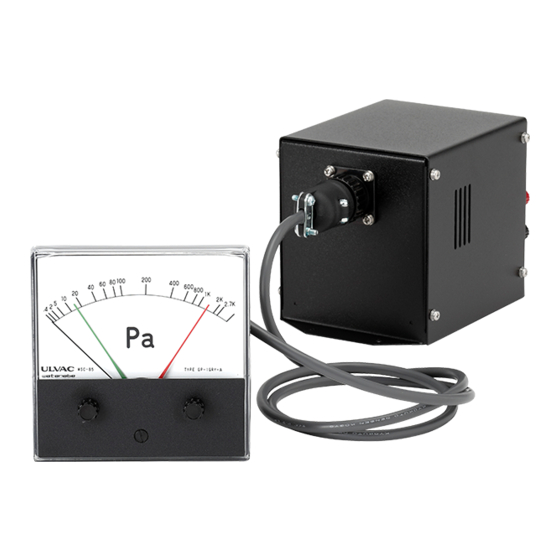
- Page 1 No. SK00-7401-EI-004-06 MODEL GP-1GRY ( Pa/Torr ) PIRANI VACUUM GAUGE INSTRUCTION MANUAL This manual is for the following gauges. Serial Nos. T0001G and higher Read this manual before operation and keep it at your hand for immediate reference. ULVAC , Inc.
-
Page 3: Prior To Use
The copyright of this instruction manual is held by ULVAC, Inc. You are prohibited from copying any portion of this instruction manual without the consent of ULVAC Inc. -
Page 4: Safety Cautions
OFF the power. Otherwise, fire can result. For safety, contact your local ULVAC representative or ULVAC JAPAN. Turn OFF power. Turn OFF the power before replacing a fuse. Replacing a fuse with the power turned ON can cause electric shock. - Page 5 SAFETY CAUTIONS Operating environment Do not connect the sensor head to a test object of which pressure is in excess of atmospheric pressure. If the pressure in the sensor head exceeds atmospheric pressure, the sensor head will be damaged or it will pop out from the connector, causing injury to the surrounding, including human body.
-
Page 6: Location Of Cautionary Label
Location of Cautionary Label Meter Meaning of cautionary label Turn OFF power. Before touching any terminal on the rear of the meter or if there is a possibility of touching it, turn OFF the vacuum gauge power and the power applied to the setpoint output terminal. Contact with the terminal, to which the voltage (24 VDC) is applied, will cause electric shock if power is turned ON. -
Page 7: Revision History
Revision History Date Reason Jun.26,2007 Correction of errors Mar.3,2008 Safety cautions , maintenance added Relay contact capacity, Operating humidity rang added 2-2-4 Change connection diagram 2-2-5 Change installation method to GP-H ・Change Safety symbol mark Nov.7,2013 ・1-2 Standard Accessories added ・1.3 Add Measuring unit to Option ・6 Change WARRANTY ・7 Add CERTIFICATE OF DECONTAMINATION... -
Page 8: Table Of Contents
CONTENTS Contents Page Prior to Use ..........................i Safety Denotations ........................i Safety Cautions ........................ii Location of Cautionary Label .................... vi Revision History........................vii OVERVIEW ........................1 1.1. Specifications ....................1 1.2. Standard Accessories ..................1 1.3. Options......................1 1.3.1. -
Page 9: Overview
OVERVIEW 1. OVERVIEW The Model GP-1GRY is a constant temperature type Pirani vacuum gauge utilizing heat conduction of gas. If the sensor head burns out, the meter indication will deflect off-scale to the higher pressure side (atmospheric pressure side). Pressure can be set at two points by meter relay and the comparator output can be taken out as setpoint (transfer type). -
Page 10: Measuring Unit
OVERVIEW 1.3.2. Measuring unit Measuring unit GP-H GP-BH(Conversion cable 2m) Sensor head WP-01, WP-02, WP-03, WP-16 WPB-10, WPB-10-034 GP-BH: 0.13kg Weight Conversion calbe: 0.2kg *Because of its circuitry, the indication of this vacuum gauge varies with the type of sensor head. Therefore, if the type of sensor head is changed after delivery, re-adjustment will be required. -
Page 11: Description Of Components
OVERVIEW 1.4. Description of Components 1 Fig. 1 Front panel of controller ① Meter connector Connect this connector to the meter incorporated in the controller. - 3 -... - Page 12 OVERVIEW Fig. 2 Rear panel of controller ② Fuse holder The fuse ampacity is 0.5A. ③ Sensor head connector Connect to the sensor head cable. ④ Recorder output adjustment ADJ. The recorder has been factory adjusted to an output voltage of 10 mV with the full scale. If this value is deviated or if you want to change it, use this ADJ.
- Page 13 OVERVIEW 1 3 2 4 Fig. 3 Meter front panel ① Meter Pressure indicator. Indicates pressure by needles. ② Relay potentiometer Sets the meter relay L. ③ Relay potentiometer Sets the meter relay H. ④ Zero adjustment Adjust the meter needle to the zero position (extreme left of scale) when power is OFF. - 5 -...
- Page 14 OVERVIEW ① M - ② M + POWER H L ③ ⑧ ④ ⑦ ⑥ ⑤ 6 5 Fig. 4 Rear panel of Meter rear panel ⑤ Setpoint output terminal Outputs setpoint L. ⑥ Setpoint output terminal Outputs setpoint H. The recorder output is afloat from ground potential.
-
Page 15: Installing The Pirani Gauge
INSTALLING THE PIRANI GAUGE 2. INSTALLING THE PIRANI GAUGE Turn OFF power. Whenever mounting the gauge, unplug the power cable. 2.1. Preliminary Operation Unpack the gauge and check quantities. Check components for possible damage. 2.2. Installation 2.2.1. Installing the controller Turn OFF power Before touching any terminal on the rear of the meter or if there is a possibility of touching it, turn OFF the vacuum gauge power and the power... -
Page 16: Installing The Sensor Head
INSTALLING THE PIRANI GAUGE 2.2.3. Installing the sensor head Operating environment Do not connect the sensor head to a test object of which pressure is in excess of atmospheric pressure. If the pressure in the sensor head exceeds atmospheric pressure, the sensor head will be damaged or it will pop out from the connector, causing injury to the surrounding, including human body. - Page 17 Meter:B-Type Power supply GP-1GRY Controller cord (3m) Meter:C-Type Sensor head cable (2-100m) Measuring unit:GP-H (WP-01,02,03,16) WP-01 Conversion cable WP-04,05 (2m) Measuring unit:GP-BH (WP-04,05,WPB-10) WP-04 WPB-10-034 Conversion cable WPB-10 (2m) Fig. 5 GP-1GRY connection diagram - 9 -...
-
Page 18: A Sensor Head Installation Method To Gp-H
INSTALLING THE PIRANI GAUGE 2.2.5. A sensor head installation method to GP-H Caution: The installation methods of a screw for fixation are different by a sensor head. ①Install a screw for fixation that is attached to GP-H to a sensor head. By the kind of the sensor head, installation... -
Page 19: Operating Procedure
OPERATING PROCEDURE 3. OPERATING PROCEDURE 3.1. Handling Before operating the gauge, make sure that components are securely connected. • Start measurement more than one minute after power is turned ON and the indication is stabilized. • For precision measurement, wait for at least 10 minutes until temperature equilibrium of the sensor head is established after power is turned ON. -
Page 20: Meter Relay Action
OPERATING PROCEDURE 3.2. Meter Relay Action Connection The contact output capacity is 125 VAC 1 A (resistance load). If power higher than this is opened/closed, do not use the contact of the vacuum gauge, but use a large capacity switch in conjunction. Range in which meter relay setting is effective •... -
Page 21: Recorder Output
OPERATING PROCEDURE 3.3. Recorder Output Check recorder connection The recorder output is afloat from ground potential. Always connect the recorder input to the recorder terminal by insulating it from ground. If it is connected to GND potential by mistake, the meter will not indicate the correct value. - Page 22 OPERATING PROCEDURE Fig. 6 Pressure vs. recorder output curve - 14 -...
-
Page 23: Troubleshooting
Possible cause Corrective action • Pressure is beyond the measurable (1) The measurable range of the GP-1GRY is 0.4 to 2700 Pa. range. (0.003 to 20 Torr.) • Sensor head cable is not connected. Reconnect the sensor head cable after turning OFF the power to the controller. - Page 24 TROUBLESHOOTING Symptom: The indicator does not exceed 2 kPa when atmospheric pressure is measured. Possible cause Corrective action • The type of the sensor head or Change it with a specified one. sensor head cable length differs Adjust or recalibrate with the one currently in use. from the specified one.
- Page 25 TROUBLESHOOTING Symptom: Pointer does not move from the right(Atm pressure)but it start moving suddenly after the pressure decreases. Possible cause Corrective action • The gauge has been exposed to high (1) Use the gauge at condition as listed on the specification. temperature and high humidity above the (2) If the same problem occurs in the regular environment, specification for long time.
-
Page 26: Appendix
α directly affects the accuracy and stability of the vacuum gauge. The constant temperature type Pirani gauge supplies the energy lost by collision of gas molecules from the heated filament and maintains the filament temperature constant all the time. The ULVAC Pirani gauge is this type of gauge. -
Page 27: Types Of Gas Measured And Indication
APPENDIX 5.2. Types of Gas Measured and Indication As briefly explained in "5.1 Principles of Operation", the indication of the Pirani vacuum gauge changes with the type of gas measured. In the molecular flow region, A (free molecule thermal conductivity) is given by the following equation. - Page 28 APPENDIX H 2 H e N 2 O 2 A r C O 2 Indication of Pirani gauge (Pa) Indication of Absolute pressure of Gas (Pa) Pirani gauge (Pa) 3.1E-1 9.7E-1 5.3E-1 5.3E-1 5.9E-1 3.7E-1 7.4E-1 2.0E-1 4.3E-1 7.8E-1 8.2E-1 6.0E-1 8.2E-1 1.5E+1...
-
Page 29: Accuracy Of Pirani Vacuum Gauge
APPENDIX 5.3. Accuracy of Pirani Vacuum Gauge The relationship between pressure and output of a Pirani vacuum gauge is nonlinear and its accuracy range varies with pressure values. To express the outgoing inspection criterion for a Pirani vacuum gauge, it is defined as "within ± 3% of 100% full scale as converted to the linear scale " and is given in the instruction manual as measurement accuracy. - Page 30 APPENDIX 1000 1000 Indicated Values (Pa) 0.01 0.003 0.01 Indicated Values (Torr) Indication Values – Working Standard Fig. 9 - 22 -...
- Page 31 APPENDIX Causes of deviation from measurement accuracy Ambient temperature The indication of the Pirani gauge varies with the ambient temperature of the sensor head. Gas measured Since the Pirani gauge is a molecular density measuring vacuum gauge, the indication of the gauge varies with the type of gas (difference in thermal conductivity).
-
Page 32: Warranty
1) In case, special agreement or memorandum for specifications is made individually, the descriptions are prior to this article “13 Product Warranty”. 2) Buyer shall inform ULVAC when this product is exported out of Japan. In the meantime, Buyer shall take necessary procedures according to Foreign Exchange and Foreign Trade Law. -
Page 33: Certificate Of Decontamination
CERTIFICATE OF DECONTAMINATION 7. CERTIFICATE OF DECONTAMINATION - 25 -... -
Page 34: China Rohs Declaration
CHINA ROHS DECLARATION 8. CHINA ROHS DECLARATION This mark is applied to the electronic information product sold in the People's Republic of China. The figure at the center of the mark is the validity date of environmental protection. This product does not influence the environment, the human body and the property during the period reckoning the manufacturing date as long as the caution for safe use regarding the products are observed. -
Page 35: Related Drawings
RELATED DRAWINGS 9. RELATED DRAWINGS Fig. 10 Meter/controller connection diagram - 27 -... - Page 36 RELATED DRAWINGS Fig. 11 Dimensional drawing for controller - 28 -...
- Page 37 RELATED DRAWINGS Fig. 12 Dimensional drawing for A-type meter - 29 -...
- Page 38 RELATED DRAWINGS Fig. 13 Dimensional drawing for B-type meter - 30 -...
- Page 39 RELATED DRAWINGS Fig. 14 Dimensional drawing for C-type meter - 31 -...
- Page 40 RELATED DRAWINGS Fig. 15 Dimensional drawing for measuring unit GP-H - 32 -...
- Page 41 RELATED DRAWINGS Fig. 16 Dimensional drawing for measuring unit GP-BH - 33 -...
- Page 42 RELATED DRAWINGS Pin No. Label Mater terminal M+ M+ M- M- ①U(+) DC24V ②U(-) Fig. 17 Mater cable GP-1GRY connection diagram (2,5,10,15,20,30,50,100m) Pin No. +15V Cover Fig. 18 Sensor head cable connection diagram - 34 -...
- Page 43 φ 3/8 WP-03 BS (Ni plating) Socket type Pt (φ 25µ) WP-16 BS (Ni plating) Socket type NW-16(φ 30) Pt (φ 25µ) WPB-10-034 UFC-034 SUS304 Pt (φ 25µ) Fig. 19 List of sensor heads compatible with GP-1GRY - 35 -...
- Page 44 RELATED DRAWINGS WPB-10-*** WP-01,02,03,16 Fig. 20 Sensor head filament connection diagram - 36 -...
Need help?
Do you have a question about the GP-1GRY and is the answer not in the manual?
Questions and answers