Ulvac G-Tran ISG1 Manuals
Manuals and User Guides for Ulvac G-Tran ISG1. We have 3 Ulvac G-Tran ISG1 manuals available for free PDF download: Instruction Manual

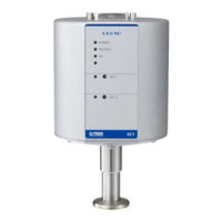
Ulvac G-Tran ISG1 Instruction Manual (107 pages)
1CH Display Unit
Brand: Ulvac
|
Category: Control Unit
|
Size: 2 MB
Table of Contents
-
7 Setpoint
33 -
-
Input Signal37
-
-
Front Panel38
-
-
Front Panel42
-
Signals44
-
-
Front Panel46
-
-
Setpoint49
-
-
Front Panel50
-
-
Front Panel56
-
-
Front Panel62
-
-
Front Panel68
-
-
Front Panel74
-
-
22 Rs485
90-
Setting90
-
Command95
-
Checksum97
-
-
When Writing98
-
When Reading99
-
In Reading100
-
-
ASCII Code Table101
-
24 Warranty
104
Advertisement

Ulvac G-Tran ISG1 Instruction Manual (107 pages)
Brand: Ulvac
|
Category: Measuring Instruments
|
Size: 1 MB
Table of Contents
-
7 Setpoint
34 -
-
Input Signal38
-
-
Front Panel39
-
-
Setpoint42
-
-
Front Panel43
-
Signals45
-
-
Front Panel47
-
-
Setpoint50
-
-
Front Panel51
-
-
Front Panel57
-
-
Front Panel63
-
-
Front Panel69
-
-
Front Panel75
-
-
22 Rs-485
91-
Setting91
-
Command96
-
Checksum98
-
-
When Writing99
-
When Reading100
-
-
ASCII Code Table101
-
24 Warranty
104
Ulvac G-Tran ISG1 Instruction Manual (54 pages)
COLD-CATHODE ION GAUGE
Brand: Ulvac
|
Category: Accessories
|
Size: 1 MB
Table of Contents
-
Introduction10
-
Terminology10
-
Options13
-
Assembly14
-
Front Panel15
-
Installation17
-
Preparations17
-
Functions22
-
Setpoint22
-
Maintenance25
-
Reassembly35
-
Leak Test38
-
Maintenance39
-
Warranty42
-
Appendix45
Advertisement
Advertisement