
Subscribe to Our Youtube Channel
Related Manuals for Fisher & Paykel ACTIVESMART RS32A72


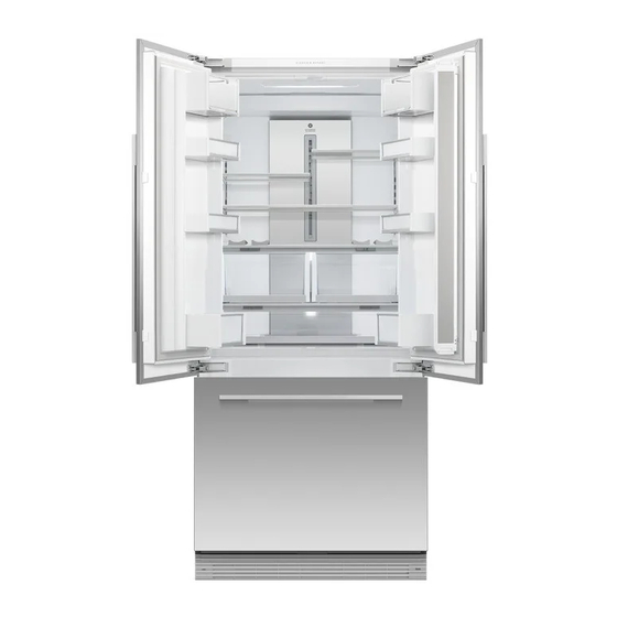
Summary of Contents for Fisher & Paykel ACTIVESMART RS32A72
- Page 1 ACTIVESMART™ INTEGRATED FRENCH DOOR REFRIGERATOR FREEZER RS32A72 and RS36A72 models INSTALLATION GUIDE US CA 862212C 08.19...
-
Page 3: Table Of Contents
CONTENTS SAFETY AND WARNINGS COMPONENTS TOOLS APPLIANCE AND CAVITY DIMENSIONS CABINETRY OPTIONS DOOR PANEL DIMENSIONS CUSTOM DOOR PANEL INSTALLATION DIMENSIONS — RS32A72 CUSTOM DOOR PANEL INSTALLATION DIMENSIONS — RS36A72 CUSTOM DOOR PANEL INSTALLATION TEMPLATE (RS32A72) CUSTOM DOOR PANEL INSTALLATION TEMPLATE (RS36A72) DOOR CLEARANCE ELECTRICAL AND PLUMBING BEFORE INSTALLATION... -
Page 5: Safety And Warnings
SAFETY AND WARNINGS IMPORTANT! WARNING! It is very important for the installer to follow the instructions in this installation guide ● to ensure proper installation and operation of the appliance. Ensure that you read the Electric Shock Hazard installation guide thoroughly and understand all information. Read and follow the safety and warnings The water connection to your Ice and water appliance must be installed by a qualified ●... - Page 6 COMPONENTS Internal box (Installation kit) External box Located inside appliance Located at back panel of appliance Cabinet side trim Anti-tip bracket Door panel attachment Door / d rawer trim assembly kit install kit install kit Door side trim Side trim bracket Anti-tip bracket Side bracket Dual adhesive tabs (6 per each strip) (10)
-
Page 7: Components
COMPONENTS Miscellaneous items (MI) pack Located inside the appliance ACTIVESMART™ INTEGRATED ACTIVESMART™ INTEGRATED REFRIGERATOR SLIDE-IN REFRIGERATOR RS90A, RS9120W, RS90 & RS90AU models RS36A72, RS36A80 & RS36W80 models SERVICE & WARRANTY SERVICE ET GARANTIE ΣΈΡΒΙΣ ΚΑΙ ΕΓΓΎΗΣΗ SERVIZIO E GARANZIA SERVICE & GARANTIE HUOLTO JA TAKUU SERVICE OG GARANTI INSTALLATION GUIDE... -
Page 8: Tools
COMPONENTS TOOLS Door panel set Required tools Not supplied and must be purchased separately Not included with appliance Stainless steel (Fisher & Paykel) door panel set: Custom door panel set: Includes 2x French door panels and 1x drawer panel. Supplied by customer to match their cabinetry. Applicable for Ice only appliance models. -
Page 9: Appliance And Cavity Dimensions
APPLIANCE AND CAVITY DIMENSIONS IMPORTANT! For ease of installation, ensure cavity width is consistent top to bottom and height is consistent left to right. Flush with front of cabinetry PLAN VIEW Flush install Flush install Framed: Finished return top and sides Frameless: Finished return top and sides FRONT VIEW PROFILE VIEW... -
Page 10: Cabinetry Options
CABINETRY OPTIONS FRAMELESS CABINETRY FRAMED CABINETRY (Aligns the appliance with the cabinetry) (Aligns the appliance with the frame of the cabinetry) Flush Proud installation installation Note: Drawings are only for reference and not the actual cavity width of the cabinetry. -
Page 11: Door Panel Dimensions
DOOR PANEL DIMENSIONS IMPORTANT! Custom door panels can only be used for non-Water dispensing models. ● Custom door panels to be manufactured and fitted by cabinetmaker. ● Door handle kit must be purchased separately. ● STAINLESS STEEL/CUSTOM DOOR PANELS RS32A72 RS36A72 DIMENSIONS Height of each top door panel... -
Page 12: Custom Door Panel Installation Dimensions - Rs32A72
CUSTOM DOOR PANEL INSTALLATION DIMENSIONS — RS32A72 Dimensions apply for the preparation and installation of custom door panels. For Dwg and Dxf files of the below panel preparation download the folder on http://thekitchentools.fisherpaykel. com/downloads/. 13 1/2" (342.3mm) 2 3/16" (54.8mm) Ø 2mm REF 12x Pilot holes recommended for bracket attachment. -
Page 13: Custom Door Panel Installation Dimensions - Rs36A72
CUSTOM DOOR PANEL INSTALLATION DIMENSIONS — RS36A72 Dimensions apply for the preparation and installation of custom door panels. For Dwg and Dxf files of the below panel preparation download the folder on thekitchentools.fisherpaykel.com. 15 7/16" (392.3mm) 2 3/16" (54.8mm) Ø 3/32" (2mm) REF 12x Pilot holes recommended for bracket attachment. -
Page 14: Custom Door Panel Installation Template (Rs32A72)
CUSTOM DOOR PANEL INSTALLATION TEMPLATE (RS32A72) This template is a single double-sided sheet used as a guide to drill screw holes for installing your Custom door and drawer panels. The actual template is included with this installation guide. HANGING BRACKET HANGING BRACKET HANGING BRACKET HANGING BRACKET... -
Page 15: Custom Door Panel Installation Template (Rs36A72)
CUSTOM DOOR PANEL INSTALLATION TEMPLATE (RS36A72) This template is a single double-sided sheet used as a guide to drill screw holes for installing your Custom door HANGING BRACKET HANGING BRACKET HOLES HOLES and drawer panels. The actual template is included with this installation guide. -
Page 16: Door Clearance
DOOR CLEARANCE Insert hinge limiting pin WARNING! Before opening the doors, ensure that the appliance is ● stable. Follow these steps to avoid risks that can cause serious ● injury or death. For 90° door swing, a hinge limiting pin is supplied with Wall Wall your appliance. -
Page 17: Electrical And Plumbing
ELECTRICAL AND PLUMBING IMPORTANT! WARNING! Electrical connection should be located in an adjacent cabinet to either side Electrical shock hazard. Assume all parts are live. ● ● of the appliance or above the appliance cavity. Disconnect supply before servicing and installation. ● We recommend to use an isolating switch that is easily accessible to the user ●... - Page 18 ELECTRICAL AND PLUMBING Maximum distance of hose and power cord Power cord (excl. plug) — 31 1/2" (800mm) Checking your appliance Detach accessories box taped to back panel of appliance. Refer to 'Components' (page 5). IMPORTANT! Be aware when removing the carton that the accessories box may have dislodged from the rear of the appliance during transit.
-
Page 19: Before Installation
BEFORE INSTALLATION IMPORTANT! Be careful when unpacking to prevent damage to the surface of your appliance. Ensure that the feet of the appliance are retracted. ● ● Ensure that the appliance is stable to prevent from tipping over when unpacking. If the appliance is damaged, contact your Fisher &... - Page 20 BEFORE INSTALLATION IMPORTANT! Your appliance is fitted with front and rear rollers designed for moving the appliance All connections for water, electrical power and grounding must comply with local codes ● ● forward and backward. Do not move the appliance sideways as this may damage the and ordinances and be made by licensed personnel when required.
-
Page 21: Cavity Preparation
CAVITY PREPARATION IMPORTANT! WARNING! Internal box The anti-tip bracket and fittings supplied must be fitted to the wall Read the following before fastening with masonry plugs and / o r screws: ● of the finished enclosure to withstand 220lbs (100kg) load. Ensure the screws avoid electrical, gas and water conduits. -
Page 22: Water Supply Connection
WATER SUPPLY CONNECTION IMPORTANT! Miscellaneous items (MI) pack The water connection instructions below are intended only for Ensure there is enough tubing for the water connection and to pull ● ● the professional installer. the appliance out for service, if required. The appliance comes with a pre-connected plastic water tubing. Flush water through the hose prior to connection to the appliance ●... -
Page 23: Power Supply Connection
POWER SUPPLY CONNECTION DETAIL B SCALE 1 : 5 Internal box Connect to power supply Alternative water and electrical connection (above the cavity) Connect the water fittings to the water supply (C). Locate the power cord and connect the fitted plug to the electrical supply Miscellaneous (115 V, 60 Hz). -
Page 24: Installation Preparation
INSTALLATION PREPARATION WARNING! Internal box Be careful when working with the appliance outside of the finished enclosure. ● Ensure that the appliance is secured to prevent tipping forward. Tipping of appliance can lead to serious injury or death. Install ● fasteners kit Remove hinge end caps M5x10 cross-head screw Open the French doors carefully. -
Page 25: Top Trim Installation
TOP TRIM INSTALLATION Internal box Install the top trim Position the top trim on top of the top cover of the Small screw hole Top trim Install appliance (A). fasteners kit Align the small screw hole of the top trim with the screw hole of the hinge bracket (B). -
Page 26: Positioning Into Cabinetry
POSITIONING INTO CABINETRY IMPORTANT! Your appliance is fitted with front and rear rollers designed for moving the appliance in Ensure the hose is not run over by the appliance when pushing into the cabinetry to ● ● ● ● the forwards and backwards direction. prevent damage and possible water leaks. -
Page 27: Aligning Inside Cabinetry
ALIGNING INSIDE CABINETRY IMPORTANT! Supplied tools Ensure all four corners of the appliance is supported firmly onto the floor If using a powered driver, use low torque setting to avoid the nut ● ● to eliminate any movement. disengaging from the rod and damaging the leveling system. If the nut DO NOT install the appliance on a soft, uneven, or unlevelled floor disengages, use the hex key to realign with rod. - Page 28 DOOR PANEL INSTALLATION — STAINLESS STEEL IMPORTANT! Internal box Follow these steps to avoid difficulties in door panel adjustment and cosmetic cap fitment. ● Ensure to protect the finish of the Stainless steel door panels. Door panel ● For non-water dispensing door panels: Leave the protective film on the panels when hanging and remove the film only when installation is complete. attachment kit ●...
- Page 29 DOOR PANEL INSTALLATION — STAINLESS STEEL IMPORTANT! Ice and Water display (Ice and Water models Failure to follow these steps can lead to difficulties in door panel adjustment and cosmetic cap fitment. ● only) For water dispensing door panels: Remove the protective film from the appliance doors before hanging door panels. ●...
- Page 30 DOOR PANEL INSTALLATION — STAINLESS STEEL Tools Attach the door panels Open the door and loosen the M5x10 cross-head screws (do not remove) at the sides of the doors (A). Hang the door panel by inserting the M8 studs through the holes of the hanging bracket (B). Cross-head screwdriver Slide the forks of the side brackets onto the screws of the door (C).
- Page 31 DOOR PANEL INSTALLATION — STAINLESS STEEL IMPORTANT! Door panel Follow these steps to avoid difficulties in door panel adjustment and cosmetic cap fitment. attachment ● Adjust the door panels #8Gx16 countersunk Push the appliance into the cavity until the door panels are flush screw (2) with adjacent cabinetry surface.
- Page 32 DOOR PANEL INSTALLATION — CUSTOM DRAWER PANEL TOP EDGE IMPORTANT! External box back side of front side of The template is a single sheet with one side used for the left door ● door panel door panel DRAWER PANEL TOP EDGE panel / d rawer panel and the other side for the right door panel. The template should be placed on the back side of the door panel.
- Page 33 DOOR PANEL INSTALLATION — CUSTOM DRAWER PANEL TOP EDGE IMPORTANT! front side of back side of Flip the template over to use for the left top door panel. ● door panel door panel DRAWER PANEL TOP EDGE The template should be placed on the back side of the door panel. ●...
- Page 34 DOOR PANEL INSTALLATION — CUSTOM IMPORTANT! Use left door panel template to use for the drawer panel. back side of front side of ● drawer panel door panel Place the template at the back side of the drawer panel. ● DRAWER PANEL TOP EDGE DRAWER PANEL TOP EDGE Using the installation template (for drawer panel)
- Page 35 DOOR PANEL INSTALLATION — CUSTOM Internal box Remove hanging brackets Attach the door and drawer handles (C) Remove the M8 washers and M8 nuts from the Align the handle holes with the door panel Door panel M8 studs at the top the door (A) using the hex holes and secure with M5x25 pan head socket attachment kit key and spanner.
- Page 36 DOOR PANEL INSTALLATION — CUSTOM Tools Attach the door panels Open the door and loosen the M5x10 cross-head screws (do not remove) at the sides of the doors (A). Hang the door panel by inserting the M8 studs Hex key through the holes of the hanging bracket (B). Slide the forks of the side brackets onto the screws of the door (C).
- Page 37 DOOR PANEL INSTALLATION — CUSTOM IMPORTANT! Door panel Follow these steps to avoid difficulties in door panel adjustment and cosmetic cap fitment. attachment ● Adjust the door panels #8Gx16 countersunk Push the appliance into the cavity until the door panels are flush screw (2) with adjacent cabinetry.
- Page 38 FIXING TO CABINETRY Internal box IMPORTANT! Lower the feet until it engages the floor to provide more stability to the appliance and prevent back and forth movement. Install fasteners kit #8Gx16 flat head screw Tools Cross-head screwdriver #8 x 16 Mush Washer Twin Thread Philips Screw...
- Page 39 WATER FILTER INSTALLATION IMPORTANT! Miscellaneous items pack The water filter head must be firmly pushed into the appliance and secured. incorrect installation can lead to water leaks. ● Water filter Filter handle Filter cartridge tool FRONT VIEW Filter in locked position Install the water filter Align the filter removal tool over the filter handle and turn 90°...
- Page 40 TOE KICK INSTALLATION MI Pack Install the toe kick filter and grille Fit the filter onto the rails and push until it clips securely (A). Align the top grille clips to the top plinth slots. Ensure the top grille is in the correct orientation (B). Push the grille firmly onto the appliance until the clips engage (C).
- Page 41 COVERS AND TRIMS INSTALLATION Internal box Attach the covers Attach the drawer top and side trims Open the French doors. Peel off two dual adhesive tabs and press them together Door / d rawer Attach the top covers (A) firmly to form a pair (E).
- Page 42 TWO METHODS ARE AVAILABLE FOR ATTACHING CABINET SIDE TRIMS: [A] FLEXIBLE SPRING CLIP METHOD — RECOMMENDED METHOD [B] FIXED SCREW METHOD — METHOD TO USE IF CABINET IS NOT TO SPECIFICATION (Attempt method [A]. If method [A] results in poor fitment of side trims due to cabinetry that is uneven or out of specification, use method [B]). CABINET TRIMS INSTALLATION — [A] FLEXIBLE SPRING CLIP METHOD Internal box Break off the datum lip of each side trim bracket and discard.
- Page 43 CABINET TRIMS INSTALLATION — [A] FLEXIBLE SPRING CLIP METHOD Insert the spring clip into the gap between the side trim and side trim Open the French doors. Place the assembled side trim with brackets and spring bracket, orientation as shown in figures (C) and (D). clips against the alcove side wall with the shorter lip facing the bottom (E).
- Page 44 CABINET TRIMS INSTALLATION — [B] FIXED SCREW METHOD Internal box Break off the datum lip to each side trim bracket and discard. Repeat for all side trim brackets. Cabinet side trim install kit 2" (50mm) Side trim bracket Discard ~ 69" (1753mm) Spring clip Position three side trim brackets on one side trim.
- Page 45 CABINET TRIMS INSTALLATION — [B] FIXED SCREW METHOD Place the side trim against the alcove side wall with the shorter lip facing the bottom (D). – Ensure the side trim is positioned as high as it will go. Side trim Suggestion engagemen “ensure the Side trim bracket...
- Page 46 FINAL CHECKLIST TO BE COMPLETED BY THE INSTALLER All models Ensure all internal and external packaging is removed from the appliance before use. Check all parts are installed. Ensure the appliance is level. Ensure the appliance is securely fastened to the cabinetry with the supplied anti-tip bracket and fittings.
- Page 47 RÉFRIGÉRATEUR-CONGÉLATEUR ENCASTRABLE ACTIVESMART™ À PORTES FRANÇAISES Modèles RS32A72 et RS36A72 GUIDE D’INSTALLATION US CA 862212C 08.19...
- Page 49 TABLE DES MATIÈRES CONSIGNES DE SÉCURITÉ ET MISES EN GARDE PIÈCES OUTILS DIMENSIONS DE L’APPAREIL ET DE LA CAVITÉ OPTIONS D’ARMOIRES DIMENSIONS DE PANNEAU DE PORTE DIMENSIONS D’INSTALLATION DE PANNEAU DE PORTE SUR MESURE — RS32A72 DIMENSIONS D’INSTALLATION DE PANNEAU DE PORTE SUR MESURE — RS36A72 GABARIT D’INSTALLATION DE PANNEAU DE PORTE SUR MESURE —...
-
Page 51: Consignes De Sécurité Et Mises En Garde
CONSIGNES DE SÉCURITÉ ET MISES EN GARDE IMPORTANT! MISE EN GARDE! Il est très important que l’installateur suive les instructions de ce guide d’installation ● pour assurer l’installation et le fonctionnement convenables du produit. Assurez-vous de Risque de choc électrique lire attentivement le guide d’installation et de bien comprendre toutes les informations. - Page 52 PIÈCES Boîte interne (Ensemble d’installation) Boîte externe À l’intérieur de l’appareil À l’intérieur de l’appareil Ensemble d’installation de Ensemble d’installation de Ensemble de fixation de Ensemble d’assemblage de garniture de porte / tiroir garniture latérale de bâti support antibasculement panneau de porte Garniture latérale de porte Support latéral Languettes adhésives double face...
-
Page 53: Pièces
PIÈCES Emballage d’articles divers À l’intérieur de l’appareil ACTIVESMART™ RÉFRIGÉRATEUR-CONGÉLATEUR ENCASTRABLE INTEGRATED REFRIGERATOR ACTIVESMART™ À PORTES FRANÇAISES RS90A, RS9120W, Modèles RS32A72 et RS36A72 RS36A72, RS36A80 & RS36W80 models SERVICE & WARRANTY SERVICE ET GARANTIE ΣΈΡΒΙΣ ΚΑΙ ΕΓΓΎΗΣΗ SERVIZIO E GARANZIA SERVICE &... -
Page 54: Outils
PIÈCES OUTILS Ensemble de panneau de porte Outils requis Non fourni; vendu séparément Non compris avec le produit Ensemble de panneau de porte en acier inoxydable (Fisher & Paykel) : Ensemble de panneau de porte sur mesure : Comprend 2x panneaux de portes françaises et 1x panneau de tiroir. Fourni par le client, adapté... -
Page 55: Dimensions De L'appareil Et De La Cavité
DIMENSIONS DE L’APPAREIL ET DE LA CAVITÉ IMPORTANT! Pour faciliter l’installation, assurez-vous que la largeur et la hauteur de la cavité soient uniformes du haut vers le bas et de gauche à droite. Au même niveau que le devant des armoires VUE EN PLAN Installation encastrée Installation encastrée... -
Page 56: Options D'armoires
OPTIONS D’ARMOIRES ARMOIRES SANS MONTANT ARMOIRES AVEC MONTANT (Alignement du produit avec les armoires) (Alignement du produit avec le montant des armoires) Installation Installation encastrée superposée Remarque : Les illustrations sont fournies uniquement à titre de référence et ne représentent pas la largeur de cavité réelle des armoires. -
Page 57: Dimensions De Panneau De Porte
DIMENSIONS DE PANNEAU DE PORTE IMPORTANT! Les panneaux de portes sur mesure peuvent être utilisés uniquement avec les modèles sans distributeur d’eau. ● Les panneaux de portes sur mesure doivent être fabriqués et ajustés par un ébéniste. ● L’ensemble de poignée de porte doit être acheté séparément. ●... -
Page 58: Dimensions D'installation De Panneau De Porte Sur Mesure - Rs32A72
DIMENSIONS D’INSTALLATION DE PANNEAU DE PORTE SUR MESURE — RS32A72 Les illustrations ci-dessous concernent les modèles Glaçons uniquement RS36A80J. Les dimensions sont indiquées pour la préparation et l’installation des panneaux de portes sur mesure. Pour les fichiers Dwg et Dxf de la préparation de panneau ci-dessous, téléchargez le dossier sur thekitchentools.fisherpaykel.com. 13 1/2 po (342.3mm) 2 3/16 po (54.8mm) Ø 2mm REF... -
Page 59: Dimensions D'installation De Panneau De Porte Sur Mesure - Rs36A72
DIMENSIONS D’INSTALLATION DE PANNEAU DE PORTE SUR MESURE — RS36A72 Les illustrations ci-dessous concernent les modèles Glaçons uniquement RS36A80J. Les dimensions sont indiquées pour la préparation et l’installation des panneaux de portes sur mesure. Pour les fichiers Dwg et Dxf de la préparation de panneau ci-dessous, téléchargez le dossier sur thekitchentools.fisherpaykel.com. 15 7/16 po (392.3mm) 2 3/16 po (54.8mm) Ø 3/32"... -
Page 60: Gabarit D'installation De Panneau De Porte Sur Mesure - Rs32A72
GABARIT D’INSTALLATION DE PANNEAU DE PORTE SUR MESURE — RS32A72 Ce gabarit est une feuille double face utilisée comme guide de perçage des trous de vis pour l’installation de vos panneaux de portes et tiroir sur mesure. Le gabarit est compris avec ce guide d’installation. HANGING BRACKET HANGING BRACKET HANGING BRACKET... -
Page 61: Gabarit D'installation De Panneau De Porte Sur Mesure - Rs36A72
GABARIT D’INSTALLATION DE PANNEAU DE PORTE SUR MESURE — RS36A72 Ce gabarit est une feuille double face utilisée comme guide de perçage des trous de vis pour l’installation de HANGING BRACKET HANGING BRACKET HOLES HOLES vos panneaux de portes et tiroir sur mesure. Le gabarit est compris avec ce guide d’installation. -
Page 62: Dégagement De La Porte
DÉGAGEMENT DE LA PORTE Insertion de la tige de limitation de charnière MISE EN GARDE! Avant d’ouvrir les portes, assurez-vous que l’appareil ● est stable. Suivez ces étapes pour éviter les risques de blessures ● graves ou mortelles. Pour une rotation de porte à 90°, utilisez la tige de OUVERTURE DE LA PORTE À... -
Page 63: Raccordement Électrique Et Plomberie
RACCORDEMENT ÉLECTRIQUE ET PLOMBERIE IMPORTANT! MISE EN GARDE! Le raccordement électrique doit être situé dans une armoire adjacente d’un côté ou de Risque de choc électrique. Présumez que toutes les pièces sont sous tension. ● ● l’autre du produit, ou encore au-dessus de la cavité du produit. Déconnectez l’alimentation avant de procéder à... - Page 64 RACCORDEMENT ÉLECTRIQUE ET PLOMBERIE Distance maximale du tuyau et du cordon d’alimentation Cordon d’alimentation (excluant la fiche) — 31 1/2 po (800 mm) CÔTÉ GAUCHE CÔTÉ DROIT Tuyau d’alimentation en eau — 125 3/16 po (3180mm) Tuyau d’alimentation en eau — 154 3/4 po ( 3930 Cordon d’alimentation (excluant la fiche) — 80 11/16 po (2050mm) SPÉCIFICATIONS ÉLECTRIQUES SPÉCIFICATIONS DE PLOMBERIE Alimentation...
-
Page 65: Avant L'installation
AVANT L’INSTALLATION IMPORTANT! Déballez votre produit avec soin pour éviter d’en endommager la surface. Si le produit est endommagé, communiquez avec votre détaillant Fisher & Paykel. ● ● Assurez-vous que le produit est stable afin d’éviter tout basculement pendant le déballage. Notez les numéros de modèle et d’enregistrement situés dans le coin inférieur droit du ●... - Page 66 AVANT L’INSTALLATION IMPORTANT! Le produit est muni de roulettes avant et arrière qui facilitent le déplacement vers Tous les raccordements d’alimentation en eau, d’alimentation électrique et de mise à ● ● l’avant et l’arrière. Pour éviter d’endommager les roulettes ou le revêtement / la surface la terre doivent être conformes aux codes et règlements locaux et être effectués par du plancher, ne déplacez pas le produit latéralement.
-
Page 67: Préparation De La Cavité
PRÉPARATION DE LA CAVITÉ IMPORTANT! MISE EN GARDE! Boîte interne Le support antibasculement et les raccords fournis doivent être installés au Lisez les consignes suivantes avant d’effectuer la fixation avec des vis ● Ensemble de mur de l’emplacement d’encastrement fini afin de procurer une capacité de et/ou chevilles pour maçonnerie : support anti- charge de 220 lb (100 kg). -
Page 68: Connexion D'alimentation En Eau
CONNEXION D'ALIMENTATION EN EAU IMPORTANT! Emballage d’articles divers Les instructions de raccordement de la conduite d’eau présentées Veillez à ce que le réfrigérateur soit raccordé à son propre interrupteur ● ● À l’intérieur de ci-dessous sont destinées uniquement à un installateur professionnel. de sectionnement. -
Page 69: Connexion D'alimentation
CONNEXION D'ALIMENTATION DETAIL B SCALE 1 : 5 Boîte interne Raccordement de l’alimentation électrique Autre emplacement possible pour les raccordements d’alimentation en eau et d’alimentation électrique Localisez le cordon d’alimentation et branchez la fiche à l’alimentation Miscellaneous électrique (115 V CA, 60 Hz) (F). Mettez le produit en marche (ON). Connectez les raccords à... -
Page 70: Préparation De L'installation
PRÉPARATION DE L'INSTALLATION WARNING! Boîte interne Soyez prudent lorsque vous effectuez des travaux pendant que le réfrigérateur est à l’extérieur de l’emplacement d’encastrement fini. ● Ensemble Assurez-vous que le réfrigérateur soit bien fixé pour éviter qu’il ne bascule vers l’avant. Le basculement du réfrigérateur peut entraîner des blessures graves, ●... - Page 71 INSTALLATION DE LA GARNITURE SUPÉRIEURE Boîte interne Installation de la garniture supérieure Positionnez la garniture supérieure sur le dessus du Petit trou de vis Garniture supérieure Ensemble couvercle supérieur du produit. (A) de fixations d’installation Alignez le petit trou de vis de la garniture supérieure avec le trou de vis du support Couvercle supérieur de charnière (B).
- Page 72 POSITIONNEMENT DANS LES ARMOIRES IMPORTANT! Votre appareil est muni de roulettes avant et arrière qui facilitent le déplacement de Pour éviter de causer des dommages et de possibles fuites d’eau, veillez à ne pas passer ● ● l’appareil vers l’avant et l’arrière. sur le tuyau lors du déplacement du produit dans les armoires.
- Page 73 ALIGNEMENT DANS LES ARMOIRES IMPORTANT! Outils N’installez PAS le produit sur un plancher souple, inégal ou qui n’est Lors de l’utilisation d’une visseuse électrique, utilisez un réglage à faible ● ● pas de niveau, car cela pourrait entraîner une déformation du produit et couple pour éviter que l’écrou se désengage de la tige et endommage le compromettre l’étanchéité...
- Page 74 INSTALLATION DE PANNEAU DE PORTE — EN ACIER INOXYDABLE IMPORTANT! Boîte interne Suivez ces étapes pour éviter des difficultés lors de l’ajustement du panneau de porte et l’installation du capuchon esthétique. ● Ensemble Assurez-vous de protéger le fini des panneaux de portes en acier inoxydable. ●...
- Page 75 INSTALLATION DE PANNEAU DE PORTE — EN ACIER INOXYDABLE IMPORTANT! Afficheur Glaçons et eau Le fait de ne pas suivre ces étapes pourrait entraîner des difficultés lors de l’ajustement du panneau de porte et l’installation du capuchon esthétique. ● (Modèles Glaçons Pour les panneaux de portes avec distributeur d’eau : Retirez la pellicule protectrice des portes du produit avant de suspendre les panneaux de portes. ●...
- Page 76 INSTALLATION DE PANNEAU DE PORTE — EN ACIER INOXYDABLE Outils Fixation des panneaux de portes Ouvrez la porte et desserrez les vis cruciformes M5x10 (ne les retirez pas) sur les côtés des portes (A). Suspendez le panneau de porte en insérant les goujons M8 dans les trous du support Clé...
- Page 77 INSTALLATION DE PANNEAU DE PORTE — EN ACIER INOXYDABLE IMPORTANT! Ensemble de Suivez ces étapes pour éviter des difficultés lors de l’ajustement du panneau de porte et l’installation du capuchon esthétique. fixation de ● panneau de porte Ajustement des panneaux de portes Poussez l’appareil dans la cavité...
- Page 78 INSTALLATION DE PANNEAU DE PORTE — SUR MESURE DRAWER PANEL TOP EDGE IMPORTANT! Boîte externe face arrière du face avant du Le gabarit est une simple feuille dont un côté est utilisé pour le panneau ● panneau de porte panneau de porte DRAWER PANEL TOP EDGE de la porte gauche ...
- Page 79 INSTALLATION DE PANNEAU DE PORTE — SUR MESURE DRAWER PANEL TOP EDGE IMPORTANT! face avant du face arrière du Retournez le gabarit pour l’utiliser avec le panneau supérieur de la ● panneau de porte panneau de porte DRAWER PANEL TOP EDGE porte gauche. Le gabarit doit être placé...
- Page 80 INSTALLATION DE PANNEAU DE PORTE — SUR MESURE IMPORTANT! Utilisez le gabarit du panneau de porte gauche pour le panneau de tiroir. face arrière du face avant du ● panneau de tiroir panneau de porte Placez le gabarit sur la face arrière du panneau de tiroir. ●...
- Page 81 INSTALLATION DE PANNEAU DE PORTE — SUR MESURE Boîte interne Retrait des supports d’accrochage Fixation des poignées de porte et de tiroir (C) Ensemble Retirez les rondelles M8 et les écrous M8 des goujons Alignez les trous de poignée avec les trous du de fixation M8 dans le haut de la porte (A).
- Page 82 INSTALLATION DE PANNEAU DE PORTE — SUR MESURE Outils Fixation des panneaux de portes Ouvrez la porte et desserrez les vis cruciformes M5x10 (ne les retirez pas) sur les côtés des portes (A). Suspendez le panneau de porte en insérant les goujons M8 dans les trous du support d’accrochage (B).
- Page 83 INSTALLATION DE PANNEAU DE PORTE — SUR MESURE IMPORTANT! Ensemble de Suivez ces étapes pour éviter des difficultés lors de l’ajustement du panneau de porte et l’installation du capuchon esthétique. fixation de ● panneau de porte Ajustement des panneaux de portes Poussez l'appareil dans la cavité jusqu'à ce que les panneaux de Vis rondelle n° 8x16 (Sur la porte soient au même niveau que les armoires adjacentes.
- Page 84 FIXATION AUX ARMOIRES Boîte interne IMPORTANT! Abaissez les pattes afin qu’elles reposent au sol pour procurer une Ensemble meilleure stabilité à l’appareil et empêcher les mouvements d’un de fixations côté à l’autre. d’installation Vis à tête fraisée 8Gx16 Outils Tournevis cruciforme #8 x 16 Mush Washer Twin Thread...
- Page 85 INSTALLATION DU FILTRE À EAU IMPORTANT! Emballage d’articles divers La tête du filtre à eau doit être enfoncée fermement dans le produit et fixée, car une installation incorrecte pourrait entraîner des fuites d’eau. ● Filtre à eau Poignée du filtre Outil de cartouche filtrante (1) VUE DE FACE Filtre en position verrouillée...
- Page 86 INSTALLATION DE LA PLINTHE Emballage d’articles Installez le filtre et la grille de la plinthe divers Installez le filtre sur les rails, puis poussez vers l’arrière jusqu’à ce qu’il s’enclenche solidement. (A). Alignez les clips de la grille du haut avec les fentes de la plinthe supérieure. Assurez-vous de placer la grille du haut dans le bon sens (B).
- Page 87 INSTALLATION DES GARNITURES DE PORTE ET TIROIR Boîte interne Fixation des couvercles Fixation des garnitures supérieure et latérales de tiroir Ouvrez les deux portes. Fixez Détachez deux languettes adhésives doubles et pressez- Ensemble les couvercles supérieurs (A) les l'une contre l'autre pour former une paire (E). Retirez d’installation fermement sur les goujons dans le le support adhésif sur un côté...
- Page 88 CHOISISSEZ L’UNE DES DEUX MÉTHODES D’INSTALLATION DES GARNITURES LATÉRALES DE BÂTI : [A] MÉTHODE AVEC CLIP DE FIXATION FLEXIBLE — MÉTHODE RECOMMANDÉE [B] MÉTHODE AVEC VIS FIXÉE — MÉTHODE À UTILISER SI LES ARMOIRES NE SONT PAS CONFORMES AUX SPÉCIFICATIONS (Essayez la méthode [A]. Si la méthode [A] ne permet pas l’ajustement adéquat des garnitures latérales parce que les armoires sont inégales ou non conformes aux spécifications, utilisez la méthode [B].) INSTALLATION DES GARNITURES DE BÂTI — [A] MÉTHODE AVEC CLIP DE FIXATION FLEXIBLE Brisez la languette de référence de chaque support de garniture latérale, Boîte interne...
- Page 89 INSTALLATION DES GARNITURES DE BÂTI — [A] MÉTHODE AVEC CLIP DE FIXATION FLEXIBLE Insérez le clip de fixation dans l’espace entre la garniture latérale Ouvrez les portes françaises. Placez la garniture latérale assemblée avec les et le support de garniture latérale, en l’orientant comme dans les supports et clips de fixation contre la paroi de l’alcôve, en orientant la languette illustrations (C) et (D).
- Page 90 INSTALLATION DES GARNITURES DE BÂTI — [B] MÉTHODE AVEC VIS FIXÉE Boîte interne Brisez la languette de référence sur chaque support de garniture latérale, puis jetez-la. Ensemble d’installation Répétez cette étape pour tous les supports de garniture latérale. de garniture latérale de bâti 2"...
- Page 91 INSTALLATION DES GARNITURES DE BÂTI — [B] MÉTHODE AVEC VIS FIXÉE Placez la garniture latérale contre la paroi de l’alcôve, avec la languette courte orientée vers le bas (D). – Assurez-vous de positionner la garniture latérale aussi haut que possible. Garniture latérale Suggestion engagemen “ensure the Support de...
- Page 92 LISTE DE VÉRIFICATION FINALE À ÊTRE REMPLIE PAR L’INSTALLATEUR Tous les modèles Assurez-vous de retirer tous les matériaux d’emballage internes et externes du produit avant l’utilisation. Vérifiez que toutes les pièces sont installées. Assurez-vous que le produit est de niveau. Assurez-vous que le produit est fixé...
Need help?
Do you have a question about the ACTIVESMART RS32A72 and is the answer not in the manual?
Questions and answers