Fisher & Paykel ACTIVESMART RS36A72 Installation Manuals
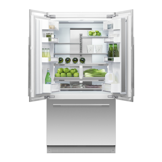
Activesmart integrated french door/drawer refrigerator
Hide thumbs
Also See for ACTIVESMART RS36A72:
- Installation manual (92 pages) ,
- User manual (80 pages) ,
- User manual (40 pages)

Related Manuals for Fisher & Paykel ACTIVESMART RS36A72


Summary of Contents for Fisher & Paykel ACTIVESMART RS36A72
- Page 1 ACTIVESMART™ INTEGRATED FRENCH DOOR/DRAWER REFRIGERATOR RS36A72 models INSTALLATION GUIDE US CA 844185A 07.18...
-
Page 3: Table Of Contents
CONTENTS FOLLOW THE INSTALLATION SEQUENCE RELEVANT TO YOUR CABINETRY 1 SAFETY AND WARNINGS 2 COMPONENTS LIST 3 PRODUCT AND CAVITY DIMENSIONS 4 CABINETRY OPTIONS 5 DOOR PANEL DIMENSIONS 6 CUSTOM DOOR PANEL INSTALLATION DIMENSIONS 7 DOOR OPENING ROTATION 8 ELECTRICAL AND PLUMBING 9 BEFORE INSTALLATION !0 ATTACH ANTI-TIP BRACKET !1 REMOVE HINGE END CAPS !2 CONNECT TO WATER AND ELECTRICAL SUPPLY !3 ALIGN YOUR PRODUCT INSIDE CABINETRY... -
Page 5: Safety And Warnings
SAFETY AND WARNINGS IMPORTANT! WARNING! The water connection to your Ice & water refrigerator must be installed by an ● ● authorized plumber or Fisher & Paykel trained and supported service technician Electric Shock Hazard and comply with all state and local laws. Read and follow the safety and warnings outlined in this installation Installation and use MUST comply with all state and local plumbing codes. -
Page 6: Components List
COMPONENTS LIST MI (miscellaneous items) pack — included with the refrigerator Anti-tip bracket fittings — included with the refrigerator ACTIVESMART™ INTEGRATED ACTIVESMART™ FRENCH DOOR/DRAWER REFRIGERATOR INTEGRATED REFRIGERATOR RS36A72 models RS90A, RS9120W, RS36A72, RS36A80 & RS36W80 models SERVICE & WARRANTY SERVICE ET GARANTIE ΣΈΡΒΙΣ ΚΑΙ ΕΓΓΎΗΣΗ SERVIZIO E GARANZIA SERVICE &... - Page 7 COMPONENTS LIST Door panel set Door panel fittings — included with the refrigerator French door hanging Drawer hanging bracket Side bracket (10x) bracket (2x) (1x) Fisher & Paykel Custom door panel (Stainless steel) set is only applicable door panel set is for non-Water not included with dispensing models.
-
Page 8: Product And Cavity Dimensions
PRODUCT AND CAVITY DIMENSIONS IMPORTANT! For ease of installation, ensure cavity width is consistent top to bottom and height is consistent left to right. Flush with front of cabinetry PLAN VIEW Flush install Frameless: Finished return top and sides FRONT VIEW PROFILE VIEW CAVITY DIMENSIONS inches (mm) -
Page 9: Cabinetry Options
CABINETRY OPTIONS FRAMELESS CABINETRY FRAMED CABINETRY (Frameless: Aligns the product with the cabinetry) (Framed: Aligns the product with the frame of the cabinetry) Frameless Framed Flush Proud installation installation Note: Drawings are only for reference and not the actual cavity width of the cabinetry. -
Page 10: Door Panel Dimensions
DOOR PANEL DIMENSIONS FRONT VIEW PROFILE VIEW STAINLESS STEEL CUSTOM DOOR PANEL DIMENSIONS inches (mm) inches (mm) ISO VIEW PROFILE VIEW Height of each top door panel 44 7/32” (1123) 44 7/32” (1123) Width of each top door panel 17 3/4” (451) 17 3/4”... -
Page 11: Custom Door Panel Installation Dimensions
CUSTOM DOOR PANEL INSTALLATION DIMENSIONS The drawings below apply to non-Water dispensing models only (RS36A72J). Dimensions apply for the preparation and installation of custom door panels. For Dwg and Dxf files of the below panel preparation download the folder on thekitchentools.fisherpaykel.com. 15 15/32”... -
Page 12: Door Opening Rotation
DOOR OPENING ROTATION Wall Wall 115° DOOR OPENING 90° DOOR OPENING (FULL ROTATION) 115° DOOR OPENING 115° DOOR OPENING 90° DOOR OPENING 90° DOOR OPENING [FULL ROTATION] [FULL ROTATION] For 90° door swing a hinge limiting pin is supplied with your DOOR CLEARANCE DIMENSIONS inches (mm) refrigerator. -
Page 13: Electrical And Plumbing
ELECTRICAL AND PLUMBING WARNING! Electrical shock hazard. Assume all parts are live. Disconnect supply before servicing and installation. Left side of cavity Recommended area above cavity for connections 31 1/2” 2 15/16” (800mm) (75mm) 5 29/32” (150mm) 4 11/32” (110mm) 5 29/32” 4 11/32” (150mm) (110mm) Floor Alternative electrical connection location 5 3/32”... - Page 14 ELECTRICAL AND PLUMBING Maximum distance of hose and power cord Power cord (excl. plug) – 31 1/2” (800mm) LEFT HAND SIDE RIGHT HAND SIDE Water inlet hose – 53 1/8” (1350mm) Water inlet hose – 83 1/2” (2120mm) Power cord (excl. plug) – 80 3/4” (2051mm) Power cord (excl.
-
Page 15: Before Installation
BEFORE INSTALLATION IMPORTANT! Ensure your appliance is not exposed to any heat generating appliances eg cooktop, oven or dishwasher. ● ● The refrigerator has front and rear rollers for moving forward and backward. Do not move the refrigerator sideways to avoid damaging the rollers or floor covering/surface. ●... -
Page 16: Attach Anti-Tip Bracket
ATTACH ANTI-TIP BRACKET IMPORTANT! WARNING! Ensure the refrigerator door is closed when rolling into cabinetry. Read the following reminders before fastening with masonry plugs and/or screws: ● ● DO NOT attempt to open the door until refrigerator is fully installed. Ensure the screws avoid electrical, gas and water conduits. -
Page 17: Remove Hinge End Caps
REMOVE HINGE END CAPS WARNING! Secure M8 studs into the refrigerator doors, ensure the open end faces the top and the Be careful when working with the refrigerator outside of the finished enclosure. studs go all the way in. Ensure that the refrigerator is secured to prevent tipping forward. Tipping of refrigerator can lead to serious injury or death. - Page 18 CONNECT TO WATER AND ELECTRICAL SUPPLY IMPORTANT! The water connection instructions below are intended only for the professional installer. ● ● Water fittings are not included in the refrigerator and must be purchased separately. ● ● Fisher & Paykel water fittings are available (part number: 841301) and comply with local regulations. ●...
-
Page 19: Connect To Water And Electrical Supply
CONNECT TO WATER AND ELECTRICAL SUPPLY IMPORTANT! Ensure water tubing is routed away from any sharp objects, sharp corners, and not in a location where it can be kinked or squashed. ● ● Beware of kinking the tube as this will stop water flow. Ensure a firm contact is observed as the refrigerator engages the anti-tip bracket, 2 3/8”... -
Page 20: Align Your Product Inside Cabinetry
ALIGN YOUR PRODUCT INSIDE CABINETRY IMPORTANT! Ensure that all four corners of the refrigerator are supported firmly onto the floor to Note: Maximum turn is 13/16” (20mm). ● ● eliminate any movement. Use low torque setting to avoid damage to height adjustment system. ●... - Page 21 INSTALL WATER FILTER AND TOE KICK GRILLE IMPORTANT! The water filter head must be firmly pushed into the product and secured. incorrect installation can lead to water leaks. ● ● Installing the water filter Installing the toe kick filter and grille Remove the plastic wrapping of the new filter.
- Page 22 ASSEMBLE DOOR PANEL SET The assembly of Fisher & Paykel (Stainless steel) door panels and custom door panels are outlined below. To protect the finish of the Fisher & Paykel Stainless steel door panels, leave protective film on the panels when hanging and remove film only when installation is complete. If using custom door panels, ensure they are prepared as per ‘Custom door panel installation dimensions’...
- Page 23 HANG ICE & WATER DOOR PANEL For Fisher & Paykel Stainless steel door panels only. Remove the external display module from inside the product. Thread the display harness through the door panel cavity. Ensure the grommet is engaged. Connect display harness onto the refrigerator door by inserting firmly until you feel it clip securely (B).
- Page 24 HANG NON-WATER DISPENSING DOOR PANELS For Fisher & Paykel Stainless steel door panels only. IMPORTANT! Remove the protective film before hanging the door panels. Hang all door panels onto M8 studs and align the side bracket forks onto the refrigerator door (A). – Ensure the forks are positioned around the body of the side screws (M5x10 pan head Phillips screw).
- Page 25 ATTACH TOP TRIM AND HINGE END CAPS Secure the top trim to the ceiling of the enclosure Replace the left hinge end cap. Align hinge cap to the product, press and firmly slide the cap to the right (refer to A). with screw x1 (#8 x 16 mush washer screw).
- Page 26 ATTACH COVERS AND DOOR/DRAWER TRIMS If applicable, remove any remaining protective film on your door panels. Open the refrigerator French doors, firmly push top cover (A) Press the dual adhesive tabs together to form pairs (E) and remove over the top studs. the adhesive backing on one side only.
- Page 27 ATTACH CABINET SIDE TRIMS IMPORTANT! Before installing your refrigerator, ensure the dimensions of the finished enclosure are correct for your refrigerator following the ‘Product and cavity dimensions’ sections. Side trim bracket Side trim Discard Top view of side trim engaged correctly in side trim bracket IMPORTANT! Each bracket has two engagement points for the side trim to locate.
- Page 28 ATTACH CABINET SIDE TRIMS Spring clip Side trim lip Top view of spring clip correctly inserted between side trim and side trim bracket IMPORTANT! IMPORTANT! Ensure spring clip is correctly oriented with the open loop facing the side trim lip. Ensure the side trim is positioned as high as it will go.
- Page 29 FINAL CHECKLIST TO BE COMPLETED BY THE INSTALLER All models Check all parts are installed. Ensure the refrigerator is level. Ensure the refrigerator is securely fastened to the cabinetry with the supplied anti-tip bracket and fittings. Ensure the doors/drawer can open and close freely with no resistance from surrounding cabinetry.
Need help?
Do you have a question about the ACTIVESMART RS36A72 and is the answer not in the manual?
Questions and answers