
Related Manuals for Lowara e-LNEEE


Summary of Contents for Lowara e-LNEEE
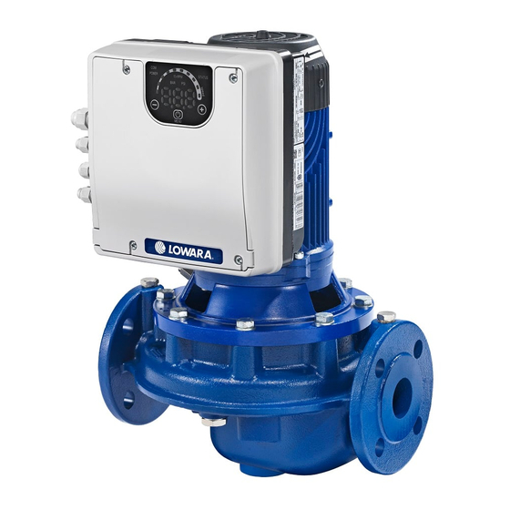
- Page 1 Smart Pump Range Installation, Operation and Maintenance Manual e-LNEEE e-LNTEE e-LNESE e-LNTSE Cod.001080138EN rev.C ed.02/2018 Software Version 151.00...
-
Page 2: Table Of Contents
en – Original instructions Table of Contents Introduction and Safety .............................. 5 Introduction ................................ 5 Safety ................................5 1.2.1 Danger levels and safety symbols ........................ 5 1.2.2 User safety ..............................6 1.2.3 General safety rules ............................7 1.2.4 Protection of the environment ........................8 1.2.5 Sites exposed to ionizing radiations ...................... - Page 3 en – Original instructions 6.3.2 STATUS ..............................27 6.3.3 SPEED (speed bar) ............................. 27 6.3.4 COM (communication) ..........................28 6.3.5 Unit of measurement ........................... 28 Display ................................29 6.4.1 Main visualization ............................29 6.4.2 Parameters menu visualization ........................29 6.4.3 Alarms and errors visualization ........................
- Page 4 en – Original instructions...
-
Page 5: Introduction And Safety
en – Original instructions 1 Introduction and Safety 1.1 Introduction Purpose of this manual The purpose of this manual is to provide necessary information for: Installation Operation Maintenance CAUTION: Before installing and using the product, make sure that you read and fully understand this manual in all its parts. -
Page 6: User Safety
en – Original instructions Special symbols Some hazard categories have specific symbols, as shown in the following table: Symbol Description Electrical hazard Magnetic hazard Hot surface hazard Ionizing radiation hazard Potentially explosive atmosphere hazard (ATEX EU Directive) Cut and abrasion hazard Crushing hazard (limbs) Other symbols Symbol... -
Page 7: General Safety Rules
en – Original instructions Inexperienced users WARNING: FOR THE EUROPEAN UNION This appliance can be used by children aged from 8 years and above and persons with reduced physical, sensory or mental capabilities or lack of experience and knowledge if they have been given supervision or instruction concerning use of the appliance in a safe way and understand the hazards involved. -
Page 8: Protection Of The Environment
If the product needs to be despatched, inform the carrier and the recipient accordingly, so that appropriate safety measures can be put in place. 1.3 Spare parts Identify the spare parts with the product codes directly on the site www.lowara.com/spark. Contact Xylem or the Authorised Distributor for technical information. -
Page 9: Product Warranty
en – Original instructions 1.4 Product warranty For information on the warranty refer to the documentation of the sale contract. -
Page 10: Transportation And Storage
en – Original instructions 2 Transportation and Storage Packaging inspection 1. Check that quantity, descriptions and product codes match the order. 2. Check the packaging for any damage or missing components. 3. In case of immediately detectable damage or missing parts: ... -
Page 11: Storage
en – Original instructions WARNING: Crushing hazard (limbs) The product and its components may be heavy: risk of crushing Always wear personal protective equipment Manual handling of the product and its components must be in compliance with the current regulations on "manual load handling", to avoid unfavourable ergonomic conditions causing risks of back-spine injury. -
Page 12: Technical Description
en – Original instructions 3 Technical Description 3.1 Designation Single stage in-line pump. 3.2 Data plates The data plate is a label showing: The main product details The identification code Approval and certifications For the approvals see the motor data plate: ... -
Page 13: Pump
208-240 : 208-240VAC 50/60Hz 380-460 : 380-460VAC 50/60Hz 230/400: 208-240/380-460VAC 50/60Hz 3.2.2 Pump e-LNEEE/e-LNESE/e-LNTEE/e-LNTSE data plate Figure 4: e-LNEEE/e-LNESE/e-LNTEE/e-LNTSE data plate 1. Pump unit set type 10. Hydraulic efficiency in best efficiency point 2. Serial number (date+progressive number) 11. Head range 3. - Page 14 – Original instructions e-LNEEE/e-LNESE/e-LNTEE/e-LNTSE identification code Figure 5: e-HME type definition code 1. Pump type [LNE] = in line, single [LNT] = in line, twin 2. Coupling [E]= Extended shaft [S] = Rigid shaft 3. Motor operation [E] = e-SM 4.
-
Page 15: Design And Layout
en – Original instructions 3.3 Design and layout The unit can be fitted with the features the application requires. Figure 9: Main components - Single-phase and three-phase models Table 1: Description of components Tightening torque ±15% Position Description number [Nm] [in•lbs] Screw 12.4... -
Page 16: Intended Use
en – Original instructions Pre-assembled ex factory components Table 2: Included components Component Quantity Notes Plug for Cable Gland 3.7 to 7.0 mm (0.145÷0.275 in) Cable gland and lock nut Cable Outer Diameter: 4.5 to 10.0 mm (0.177÷0.394 in) Cable Gland 7.0 to 13.0 mm (0.275÷0.512 in) Optional components Table 3: Optional components... -
Page 17: Improper Use
en – Original instructions 3.5 Improper use WARNING: Improper product use can create dangerous conditions and cause personal injuries and damage to property Improper product use can make the warranty void. Examples of improper use: Pumping liquids that are not compatible with the electric pump construction materials ... -
Page 18: Installation
en – Original instructions 4 Installation 4.1 Mechanical installation 4.1.1 Installation area DANGER: Potentially explosive atmosphere hazard The operation of the unit in environments with potentially explosive atmospheres or with combustible dusts (e.g.: wood dust, flour, sugars and grains) is strictly forbidden. WARNING: ... -
Page 19: Outdoor Unit Installation
en – Original instructions Figure 10: Permitted positions 4.1.3 Outdoor unit installation In case of outdoor unit installation, ensure appropriate cover (see example in Figure 11). The size of the cover must be such that the motor is not exposed to snow, rain or direct sunlight; comply with the guidelines of Par. -
Page 20: Electrical Installation
en – Original instructions 4.2 Electrical Installation DANGER: Electrical hazard The connection to the electric power supply must be completed by an electrician possessing the technical-professional requirements outlined in the current regulations. 4.2.1 Electrical requirements Local directives prevail on the specific requirements indicated below. Electrical connection checklist Check that the following requirements are met: ... -
Page 21: Power Supply Connection
en – Original instructions Table 4: Electric connection cables Power supply input cable + PE Tightening torque Wire numbers e-SM Drive models Wire numbers Mains and motor x Max. copper Earth Conductor x Max. AWG cable terminals section 103, 105, 107, 111, 3 x 1.5 mm 3 x 15 AWG Spring connectors... - Page 22 en – Original instructions Table 6: Power supply wiring procedure Reference 1. Open the terminal box cover (2) by removing the screws (1). Fig. 9 2. Insert the power cable in the M20 cable gland (5) 3. Connect the cable according to the wiring diagram. 4.
- Page 23 en – Original instructions 9 10 11 12 13 14 15 16 17 18 19 20 25 24 23 22 21 20 19 18 17 16 15 14 13 12 11 10 9 Figure 13: Connection label Table 8: I/O terminals Item Terminals Ref.
- Page 24 en – Original instructions sensor [also Differential] 10 External sensor 4-20 mA input 4÷20 mA START 11 External ON/OFF input reference External Default short circuited Pump is enabled Start/Stop to RUN STOP 12 External ON/OFF input LOW+ 13 Low water input External Default short circuited Lack of Water...
-
Page 25: Operation
en – Original instructions 5 Operation In case of co-existance of two or more of the following conditions: high ambient temperature High liquid temperature duty points insisting on unit maximum power persisting undervoltage of mains, may jeopardise the life of the unit, and/or derating may occur: for further information contact Xylem or the Authorised Distributor. -
Page 26: Programming
en – Original instructions 6 Programming Precautions NOTICE: Carefully read and follow the following instructions before starting the programming activities, to avoid wrong settings that may cause malfunctioning All modifications must be done by qualified technicians. 6.1 Control panel Figure 14: Control panel Table 10: Description of the control panel Position... -
Page 27: Description Of The Buttons
en – Original instructions 6.2 Description of the buttons Table 11: Functions of push buttons Push button Function Main view (see Par. 6.4.1): decreases the required value for the selected control mode Parameter menu (see Par. 6.4.2): decreases the displayed parameter index ... -
Page 28: Com (Communication)
en – Original instructions LED bar Status Motor in operation; the speed corresponds to the percentage step represented by the LEDs ON in the bar (e.g.: 3 LEDs ON = speed 30%) First LED flashing Motor in operation; the speed is lower than the absolute minimum, P27 Motor stopped 6.3.4 COM (communication) Condition 1... -
Page 29: Display
en – Original instructions 6.4 Display 6.4.1 Main visualization Display Mode Description Contacts 11 and 12 (see Par. 5.4) are not short-circuited. Note: It has lower display priority than STOP mode. STOP Pump stopped manually. If the pump is switched on after setting P04 = OFF (see Par. 6.5.1), it is stopped so that the motor ... -
Page 30: Alarms And Errors Visualization
en – Original instructions Parameter Description Power on If after switching ON, parameter Menu View is accessed with P23 = ON, P20 flashes: Enter the password to display and change the parameters. Password timeout If with P23 = ON no button is pressed for over 10 minutes from the last parameter Menu View, both the view and the editing of the parameters are disabled. -
Page 31: Status Parameters
en – Original instructions 6.5.1 Status Parameters Parameter Unit of Description measurement bar/psi/ rpmx10 This parameter shows the SOURCE and the VALUE of the Required value active required value. Visualization cycles between SOURCE and VALUE occur every 3 seconds. SOURCES: ... -
Page 32: Settings Parameters
en – Original instructions 6.5.2 Settings Parameters Parameter Description Password The user can enter here the system password, which gives access to all system parameters: entering this value is compared with the one stored in P22. [0÷999] When a correct password is entered, the system remains unlocked for 10 minutes. Jog mode It deactivates the internal controller of the unit and forces the actual Control Mode (ACT): [MIN÷MAX... -
Page 33: Sensor Configuration Parameters
en – Original instructions 6.5.4 Sensor Configuration Parameters Parameter Unit of Description measurement Sets the external pressure sensor parameters: Sensor selection [0÷2] = no sensor 4÷20 mA Differential sensor = Two individual 4÷20 mA pressure sensors. Pressure Sensor Unit Of This parameter sets the unit of measure ( ) for the Measure [BAR, PSI]... -
Page 34: Rs485 Interface Parameters
en – Original instructions 6.5.5 RS485 Interface Parameters Parameter Unit of Description measurement Communication protocol [MOD, This parameter selects the specific protocol on the BAC] communication port: (MOD): Modbus RTU (BAC): BACnet MS/TP. Default: MOD. Communication protocol - This parameter sets the desired address for the unit, Address [1÷247]/[0÷127] when connected to an external device, depending on... -
Page 35: Technical References
en – Original instructions 6.6 Technical references 6.6.1 Example: ACT control mode with analog 0-10V input Graph Speed [rpm] Vin [V] Figure 15: ACT control mode diagram Table 12: Description Missing input Voltage detection threshold Grey area Actual speed relative to the 0-10V analogue input voltage value (see Par. 4.3.3, table 8 contacts Speed [rpm] 7 and 8) ... -
Page 36: Maintenance
en – Original instructions 7 Maintenance Precautions DANGER: Electrical hazard Before attempting to use the unit, check that it is unplugged and that the pump and the control panel cannot restart, even unintentionally. This also applies to the auxiliary control circuit of the pump. -
Page 37: Troubleshooting
en – Original instructions 8 Troubleshooting In case of alarm or error, the display shows and ID code and the STATUS LED turns on (also see Par. 6.3.2). In case of several alarms and/or errors, the display shows the main one. Alarms and errors: ... - Page 38 en – Original instructions code Description Cause Remedy Motor stall Check that there are no foreign bodies Rotor blocked Loss of rotor synchronism or preventing the pump from turning Stop the pump for 5 minutes and then start it rotor blocked by external materials again...
-
Page 39: Technical Data
en – Original instructions 9 Technical Data Table 16: Electrical, Environmetal and Installation specifications e-SM Drive model Input Input frequency [Hz] 50/60 ± 2 Main supply L1 L2 L3 380÷ Nominal input voltage [V] 208÷240 ±10% 208÷240 / 380÷460 ±10% ±10% Maximum current absorbed (AC) in continuous service (S1) -
Page 40: Dimensions And Weights
en – Original instructions 9.1 Dimensions and weights Figure 16: Dimensions... - Page 41 en – Original instructions Table 17: Dimensions and weights Model Net weight (motor + drive) [kg] [mm] ESM90R...LNEE 14.4 ESM90RS8...LNEE 12.8 14.2 15.8 ESM90R...B14-SVE 13.1 14.5 ESM90R...B5 13.1 14.5 ESM80...HMHA 80...HMHA US 80...HMHA EU 14.5 ESM80...HMHB 80...HMHB US 80...HMHB EU 13.2 14.6 16.1...
-
Page 42: Declarations
7. Notified body: - 8. Additional information: - Signed for and on behalf of: Xylem Service Italia S.r.l. Montecchio Maggiore, 22/03/2017 Amedeo Valente (Director of Engineering and Research & Development) rev.01 Lowara is a trademark of Xylem Inc. or one of its subsidiaries. - Page 44 Xylem Service Italia S.r.l. Via Vittorio Lombardi 14 36075 – Montecchio Maggiore (VI) - Italy www.xyleminc.com/brands/lowara Lowara is a trademark of Xylem Inc. or one of its subsidiaries. © 2018 Xylem, Inc.
Need help?
Do you have a question about the e-LNEEE and is the answer not in the manual?
Questions and answers