Sign In
Upload
Manuals
Brands
IEI Technology Manuals
Industrial PC
IVS-300-ULT3-i5/4G
IEI Technology IVS-300-ULT3-i5/4G Manuals
Manuals and User Guides for IEI Technology IVS-300-ULT3-i5/4G. We have
1
IEI Technology IVS-300-ULT3-i5/4G manual available for free PDF download: User Manual
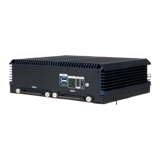
IEI Technology IVS-300-ULT3-i5/4G User Manual (110 pages)
Fanless Embedded System with lnte| Skylake ULT/ Baytrail Processor, 4 GB DDR3L/DDR4, Quad GbE LAN with PoE, On-board GPS, HDMI, VGA, Dual SSD Bay, RoHS Compliant,
Brand:
IEI Technology
| Category:
Industrial PC
| Size: 2 MB
Table of Contents
Table of Contents
7
1 Introduction
15
Overview
16
Benefits
16
Figure 1-1: IVS-300 Series Embedded System
16
Features
17
Model Variations
17
Table 1-1: Model Variations
17
Front Panel
18
LED Indicators
18
Figure 1-2: Front Panel
18
Figure 1-3: LED Indicators
18
Table 1-2: LED Indicators
19
Bottom Panel
20
Dimensions
20
Figure 1-4: Rear Panel
19
Rear Panel
19
Figure 1-5: Bottom Panel
20
Figure 1-6: Dimensions (MM)
20
Technical Specifications
21
Table 1-3: Technical Specifications
22
2 Unpacking
23
Unpacking
24
Packing List
24
Optional Items
25
Table 2-1: Package List
25
Table 2-2: Optional Items
26
3 Installation
27
Anti-Static Precautions
28
Installation Precautions
28
High Surface Temperature
29
Installation Procedure
29
Disassemble the System
30
Figure 3-1: Bottom Panel Retention Screws
31
Figure 3-2: Internal Chassis Retention Screws
31
Figure 3-3: Front Panel Retention Screws
31
Pcie Mini Card Installation
32
Figure 3-4: Rear Panel Retention Screws
32
Figure 3-5: Internal Platform Removal
32
Figure 3-6: Pcie Mini Slot Location
33
Figure 3-7: Removing the Retention Screws
33
Pcie Mini Slot (MINI-PCIE3) Pinouts
34
Figure 3-8: Inserting the Full-Size Pcie Mini Card into the Slot at an Angle
34
Figure 3-9: Securing the Full-Size Pcie Mini Card
34
Wlan/Wwan Module Installation
35
Table 3-1: Pcie Mini Slot (MINI-PCIE3) Pinouts
35
Figure 3-10: Knockouts for External Antennas
36
Figure 3-11: WLAN and WWAN Card Slot Locations
36
Figure 3-12: Connecting RF Cable
37
Figure 3-13: Securing SMA Connector and External Antenna Installation
37
WWAN Module Slot (MINI-PCIE1) Pinouts
38
Table 3-2: WWAN Module Slot (MINI-PCIE1) Pinouts
38
WLAN Module Slot (MINI-PCIE2) Pinouts
39
Table 3-3: WLAN Module Slot (MINI-PCIE2) Pinouts
39
Sim Card Installation
40
Solid-State Drive Installation
40
Figure 3-14: SIM Card Slot Locations
40
Figure 3-15: SSD Bracket Retention Screws
41
Figure 3-16: Removing SSD Bracket
41
Figure 3-17: SSD Retention Screws
42
Figure 3-18: SSD Installation
42
Mounting the System
43
Figure 3-19: Mounting Bracket Retention Screws
43
External I/O Connectors
44
COM Port Connection
44
Table 3-4: RS-232 Connector Pinouts
44
DIO and RS-422/485 (COM6) Connection
45
Figure 3-20: RS-232 Connector (COM1, COM2)
44
Table 3-5: DIO and RS-422/485 Connector Pinouts
45
Figure 3-21: DIO and RS-422/485 Connector
45
Table 3-6: OBD-II/J1939 Connector Pinouts
46
Figure 3-22: OBD-II/J1939 Connector
46
OBD-II/J1939 Connection
46
Figure 3-23: OBD-II Cable
47
Figure 3-24: OBD-II Connector Pinouts
47
GPS Speed Pulse/Direction Connection
48
Power-On Procedure
48
Installation Checklist
48
Table 3-7: GPS Speed Pulse/Direction Connector Pinouts
48
Figure 3-25: GPS Speed Pulse/Direction Connector
48
Figure 3-26: Power Input Connector
49
Figure 3-27: ACC Power Cable
49
Power Input Connection
49
Table 3-8: Power Input Connector Pinouts
49
Driver Installation
50
Figure 3-28: Power Button
50
Power-On Procedure
50
Mobile Ap
51
Installation
51
Usage
52
Figure 3-29: Mobile AP-Connection
52
RAID Configuration (ULT3 Model Only)
53
Figure 3-30: RAID Configuration-BIOS Setting
54
4 Bios
57
Introduction
58
Starting Setup
58
Using Setup
58
BIOS Menu Bar
59
Getting Help
59
Table 4-1: BIOS Navigation Keys
59
BIOS Menu 1: Main
60
System Date [XX/XX/XX]
60
System Time [XX:XX:XX]
60
Advanced
61
Main
60
BIOS Menu 2: Advanced
61
ACPI Settings
62
BIOS Menu 3: ACPI Settings
62
ACPI Sleep State [Suspend Disabled]
62
Serial Port N Configuration
63
Super IO Configuration
63
BIOS Menu 4: Super IO Configuration
63
BIOS Menu 5: Serial Port N Configuration Menu
63
Serial Port [Enabled]
63
Change Settings [Auto]
63
Serial Port [Enabled]
64
Change Settings [Auto]
64
Hardware Monitor
68
BIOS Menu 6: Hardware Monitor
68
Smart Fan Function [Enabled]
68
PC Health Status
68
Smart Fan Mode Configuration
69
BIOS Menu 7: Smart Fan Mode Configuration
69
CPU_FAN1 Smart Fan Control [Auto Duty-Cycle Mode]
69
SYS_FAN1 Smart Fan Control [[Auto Duty-Cycle Mode]
70
Power Management
71
BIOS Menu 8: Power Management
71
Low Voltage Warning [9V]
71
Auto Power on Delay [10 Sec]
71
Auto Power off Delay [20 Sec]
71
Power State
72
Table 4-2: Power State and Ignition System
72
BIOS Menu 9: CPU Configuration
73
Intel Virtualization Technology [Disabled]
73
EIST [Enabled]
74
IDE Configuration
75
CPU Configuration
73
BIOS Menu 10: IDE Configuration
75
Serial-ATA (SATA) [Enabled]
75
SATA Mode [IDE Mode]
75
USB Configuration
76
BIOS Menu 11: USB Configuration
76
USB Devices
76
Legacy USB Support [Enabled]
76
Chipset
77
BIOS Menu 12: Chipset
77
North Bridge Configuration
78
BIOS Menu 13: North Bridge
78
Intel IGD Configuration
79
BIOS Menu 14: Intel IGD Configuration
79
DVMT Pre-Allocated [256M]
79
South Bridge Configuration
80
BIOS Menu 15: South Bridge
80
DVMT Total Gfx Mem [Max]
80
Audio Controller [Enabled]
80
Security
81
BIOS Menu 16: Security
81
XHCI Mode [Smart Auto]
81
Administrator Password
81
Boot
82
BIOS Menu 17: Boot
82
User Password
82
Bootup Numlock State [On]
82
Quiet Boot [Enabled]
83
UEFI Boot [Disabled]
83
Save & Exit
84
BIOS Menu 18: Save & Exit
84
5 Troubleshooting and Maintenance
86
System Maintenance Overview
87
System Troubleshooting
87
The System Doesn't Turn on
87
More Troubleshooting
88
The System Doesn't Boot up
88
Component Replacement Procedure
89
SO-DIMM Replacement
89
Figure 5-1: SO-DIMM Locations
90
Figure 5-2: SO-DIMM Installation
90
A Regulatory Compliance
91
B Safety Precautions
96
Safety Precautions
97
General Safety Precautions
97
Anti-Static Precautions
98
Product Disposal
99
Maintenance and Cleaning Precautions
100
Cleaning Tools
100
Maintenance and Cleaning
100
CBIOS Menu Options
102
Ivs-300 Embedded System C.1 BIOS Configuration Options
103
Bios Configuration Options
103
D Watchdog Timer
105
E Hazardous Materials Disclosure
108
Advertisement
Advertisement
Related Products
IEI Technology IRS-100-ULT3
IEI Technology ITG-100-AL
IEI Technology IVS-300-BT-J1/4G
IEI Technology IVS-110
IEI Technology IVS-110-AL-E3/4G
IEI Technology IVS-110-AL-E2/4G
IEI Technology IVS-110-AL-E1/4G
IEI Technology IVS-110-AL-E3/4G-R10
IEI Technology IVS-110-AL-E2/4G-R10
IEI Technology iSDV-200CTR
IEI Technology Categories
Motherboard
Touch Panel
Computer Hardware
Single board computers
Desktop
More IEI Technology Manuals
Login
Sign In
OR
Sign in with Facebook
Sign in with Google
Upload manual
Upload from disk
Upload from URL