
Related Manuals for IEI Technology Robot-TP-65M


Summary of Contents for IEI Technology Robot-TP-65M
- Page 1 Robot-TP-65M MODEL: Robot-TP-65M Teach Pendant with 4-wire Resistive Type Touchscreen, Deadman Switch, Emergency Button, IP 64 Protection and RoHS User Manual User Manual Page I Rev. 1.01 - 7 October, 2013...
- Page 2 Robot-TP-65M Revision Date Version Changes Added Section 3.3.2: Robot-TP-65M/K Connection 7 October, 2013 1.01 Initial release 17 June, 2013 1.00 Page II...
- Page 3 Robot-TP-65M Copyright COPYRIGHT NOTICE The information in this document is subject to change without prior notice in order to improve reliability, design and function and does not represent a commitment on the part of the manufacturer. In no event will the manufacturer be liable for direct, indirect, special, incidental, or consequential damages arising out of the use or inability to use the product or documentation, even if advised of the possibility of such damages.
-
Page 4: Table Of Contents
NSTALLATION RECAUTIONS 3.3 S ....................15 YSTEM ONNECTION 3.3.1 Robot-TP-65M/K-ML Connection ..............15 3.3.2 Robot-TP-65M/K Connection ................17 3.3.2.1 OSD Keypad Connector ................18 3.3.2.2 Touch Connector ..................18 3.3.2.3 VGA Connector..................19 3.3.2.4 Cable Pinouts .................... 19 3.4 C ................... - Page 5 Robot-TP-65M A.1 S .................... 25 AFETY RECAUTIONS A.1.1 General Safety Precautions ................25 A.1.2 Anti-static Precautions ..................26 A.1.3 Product Disposal ..................... 27 A.2 M ............27 AINTENANCE AND LEANING RECAUTIONS A.2.1 Maintenance and Cleaning................27 A.2.2 Cleaning Tools ....................28 B HAZARDOUS MATERIALS DISCLOSURE ............
- Page 6 Robot-TP-65M List of Figures Figure 1-1: Robot-TP-65M Teach Pendant ...................2 Figure 1-2: Front View ........................3 Figure 1-3: LED Indicators......................3 Figure 1-4: Function Keys ......................4 Figure 1-5: Rear View ........................6 Figure 1-6: Robot-TP-65M Dimensions (mm) ................7 Figure 3-1: Robot-TP-65M/K-ML with Cable................15 Figure 3-2: 37-pin Military Connector Pinout Locations............16...
- Page 7 Robot-TP-65M List of Tables Table 1-1: LED Indicators ......................4 Table 1-2: Function Key Descriptions ..................5 Table 1-3: System Specifications....................9 Table 3-1: 37-pin Military Connector Pinouts ................17 Table 3-2: OSD Keypad Connector Pinouts................18 Table 3-3: Touch Connector Pinouts..................19 Table 3-4: VGA Connector Pinouts.....................19 Table 3-5: Cable Pinouts......................20...
-
Page 8: Introduction
Robot-TP-65M Chapter Introduction Page 1... -
Page 9: Overview
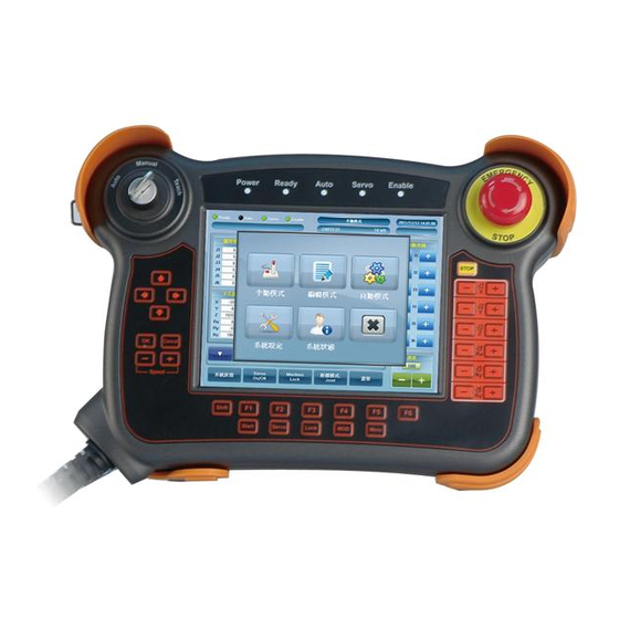
Robot-TP-65M 1.1 Overview Figure 1-1: Robot-TP-65M Teach Pendant The Robot-TP-65M is teach pendant with a 6.5” 4-wire resistive touchscreen. The Robot-TP-65M is designed for easy and simplified integration into robot arm applications. 1.2 Model Variation The Robot-TP-65M series has two models. The model variation is listed below:... -
Page 10: External Overview
1.4 External Overview 1.4.1 Front Panel The front side of the Robot-TP-65M is a flat bezel panel TFT LCD screen surrounded by a PC/ABS plastic frame. There are buttons and LED indicators located on the front panel. The detailed information is described in the following sections. -
Page 11: Function Keys
Off: the deadman switch is not pressed Table 1-1: LED Indicators 1.4.1.2 Function Keys The function keys are located on the front side of the Robot-TP-65M (Figure 1-4). Figure 1-4: Function Keys The function keys are described in Table 1-2:... -
Page 12: Table 1-2: Function Key Descriptions
Robot-TP-65M Use the Cancel button to cancel. Cancel Use “-“ to decrease the speed. Speed -/+ Use “+“ to increase the speed. Right Use the Stop button to stop the operation. Stop Use these keys to drive the robot arm manually in a designated Moving Direction direction. -
Page 13: Rear Panel
Robot-TP-65M 1.4.2 Rear Panel The rear panel provides access to the deadman switch. Refer to Figure 1-5. Figure 1-5: Rear View Page 6... -
Page 14: Dimensions
Robot-TP-65M 1.5 Dimensions The Robot-TP-65M dimensions are shown below. Figure 1-6: Robot-TP-65M Dimensions (mm) Page 7... -
Page 15: System Specifications
Robot-TP-65M 1.6 System Specifications The technical specifications for the Robot-TP-65M systems are listed in Table 1-4. Specification Robot-TP-65M LCD Size 6.5" Max. Resolution 640 (W) x 480 (H) Brightness (cd/m Contrast Ratio 600:1 LCD Color 262K Pixel Pitch (H x V) (mm) 0.207(H) x 0.207 (V) -
Page 16: Table 1-3: System Specifications
Robot-TP-65M Vibration MIL-STD-810F Drop Survival 1 m (38 inches), four corners, two sides Power Requirement 12V DC Power Consumption 6.6 W Cable Length Table 1-3: System Specifications Page 9... -
Page 17: Unpacking
Robot-TP-65M Chapter Unpacking Page 10... -
Page 18: Unpacking
To unpack the Robot-TP-65M, follow the steps below: WARNING! The front side LCD screen has a protective plastic cover stuck to the screen. Only remove the plastic cover after the Robot-TP-65M has been properly installed. This ensures the screen is protected during the installation process. -
Page 19: Packing List
Robot-TP-65M 2.1.1 Packing List The Robot-TP-65M teach pendant is shipped with the following components: Quantity Item Image Standard Robot-TP-65M teach pendant Transfer cable Belt Utility CD If any of these items are missing or damaged, contact the distributor or sales representative immediately. -
Page 20: Installation
Robot-TP-65M Chapter Installation Page 13... -
Page 21: Anti-Static Precautions
During the time the board is handled, frequently touch any conducting materials that are connected to the ground. Use an anti-static pad: - When configuring the Robot-TP-65M, place it on an antic-static pad. This reduces the possibility of ESD damaging the Robot-TP-65M. -
Page 22: System Connection
3.3 System Connection The Robot-TP-65M series has two models: Robot-TP-65M/K-ML and Robot-TP-65M/K. The only difference of these two models is that the Robot-TP-65M/K-ML has a 37-pin military connector while the Robot-TP-65M/K has multiple cables and connectors for connection. The following sections describe the system connection and connector pinouts of these two models. -
Page 23: Figure 3-2: 37-Pin Military Connector Pinout Locations
Robot-TP-65M Figure 3-2: 37-pin Military Connector Pinout Locations PIN NO. DESCRIPTION PIN NO. DESCRIPTION Key SW. - Manual RS-232 – SOUT EMG2 EMG1 RS-232 – RTS PS/2 - KBDATA PS/2 - GND RS-232 - GND LED - Servo PS/2 - chassis LED –... -
Page 24: Robot-Tp-65M/K Connection
Copper Shielding Mesh RS-232 – SIN Table 3-1: 37-pin Military Connector Pinouts 3.3.2 Robot-TP-65M/K Connection The Robot-TP-65M/K has following cables and connectors for connecting to a robot controller: OSD keypad connector (PS/2) Touch connector (DB-9 male) VGA connector (DB-15 male) -
Page 25: Osd Keypad Connector
Robot-TP-65M 3.3.2.1 OSD Keypad Connector Figure 3-4: OSD Keypad Connector Pinout Locations PIN NO. DESCRIPTION KB_DATA PS/2 VCC_IN 5V KB_CLK Table 3-2: OSD Keypad Connector Pinouts 3.3.2.2 Touch Connector Figure 3-5: Touch Connector Pinout Locations PIN NO. DESCRIPTION RS-232_RX RS-232_TX... -
Page 26: Vga Connector
Robot-TP-65M RS-232_RTS Table 3-3: Touch Connector Pinouts 3.3.2.3 VGA Connector Figure 3-6: VGA Connector Pinout Locations PIN NO. DESCRIPTION PIN NO. DESCRIPTION GREEN BLUE DDC_DATA HSYNC (Shield) RED VSYNC (Shield) GREEN DDC_CLOCK Table 3-4: VGA Connector Pinouts 3.3.2.4 Cable Pinouts... -
Page 27: Table 3-5: Cable Pinouts
Robot-TP-65M EMG 1 Yellow EMG 2 Black 3 SW.2 Switch Brown KEY SW-Teach Orange KEY SW-Manual 3-Way Green 3 SW.2 Switch Blue 3 SW.1 Purple LED_Power (VCC 12~24V) Gray LED_Ready White LED_Auto Pink LED_Servo Light green LED_Enable White/Black LED_GND Table 3-5: Cable Pinouts... -
Page 28: Carrying The System
Robot-TP-65M 3.4 Carrying the System The package comes with a belt for the user to carry the Robot-TP-65M. To use the belt, follow the steps below. Step 1: Locate the hooks on the four corners of the Robot-TP-65M (Figure 3-7). -
Page 29: Emergency Buttons
Robot-TP-65M 3.5 Emergency Buttons The Robot-TP-65M teach pendant has a deadman switch and an emergency button, which are provided to stop the robot automatically and safely when the operator can no longer operate the robot correctly with the teach pendant in the manual mode. - Page 30 Robot-TP-65M The emergency stop button is located on the front panel. Push the button can stop the robot operation immediately. STOP: Push the emergency stop button to stop operation. RESET: Pull the emergency stop button to reset or Turn the emergency stop button to rest...
-
Page 31: A Safety Precautions
Robot-TP-65M Appendix Safety Precautions Page 24... -
Page 32: Safety Precautions
Do not apply voltage levels that exceed the specified voltage range. Doing so may cause fire and/or an electrical shock. Electric shocks can occur if the Robot-TP-65M chassis is opened when the Robot-TP-65M is running. Do not drop or insert any objects into the ventilation openings of the Robot-TP-65M. -
Page 33: Anti-Static Precautions
Electrostatic discharge (ESD) can cause serious damage to electronic components, including the Robot-TP-65M. Dry climates are especially susceptible to ESD. It is therefore critical that whenever the Robot-TP-65M is opened and any of the electrical components are handled, the following anti-static precautions are strictly adhered to. -
Page 34: Product Disposal
Please follow the national guidelines for electrical and electronic product disposal. A.2 Maintenance and Cleaning Precautions When maintaining or cleaning the Robot-TP-65M, please follow the guidelines below. A.2.1 Maintenance and Cleaning Prior to cleaning any part or component of the Robot-TP-65M, please read the details below. Page 27... -
Page 35: Cleaning Tools
In such case, the product will be explicitly mentioned in the cleaning tips. Below is a list of items to use when cleaning the Robot-TP-65M. Cloth – Although paper towels or tissues can be used, a soft, clean piece of cloth is recommended when cleaning the Robot-TP-65M. -
Page 36: B Hazardous Materials Disclosure
Robot-TP-65M Appendix Hazardous Materials Disclosure Page 29... -
Page 37: Hazardous Material Disclosure Table For Ipb Products Certified As Rohs Compliant Under 2002/95/Ec Without Mercury
Robot-TP-65M B.1 Hazardous Material Disclosure Table for IPB Products Certified as RoHS Compliant Under 2002/95/EC Without Mercury The details provided in this appendix are to ensure that the product is compliant with the Peoples Republic of China (China) RoHS standards. The table below acknowledges the presences of small quantities of certain materials in the product, and is applicable to China RoHS only. - Page 38 Robot-TP-65M Part Name Toxic or Hazardous Substances and Elements Lead Mercury Cadmium Hexavalent Polybrominated Polybrominated (Pb) (Hg) (Cd) Chromium Biphenyls Diphenyl Ethers (CR(VI)) (PBB) (PBDE) Housing Display Printed Circuit Board Metal Fasteners Cable Assembly Fan Assembly Power Supply Assemblies Battery...
- Page 39 Robot-TP-65M 此附件旨在确保本产品符合中国 RoHS 标准。以下表格标示此产品中某有毒物质的含量符 合中国 RoHS 标准规定的限量要求。 本产品上会附有”环境友好使用期限”的标签,此期限是估算这些物质”不会有泄漏或突变”的 年限。本产品可能包含有较短的环境友好使用期限的可替换元件,像是电池或灯管,这些元 件将会单独标示出来。 部件名称 有毒有害物质或元素 铅 汞 镉 六价铬 多溴联苯 多溴二苯醚 (Pb) (Hg) (Cd) (CR(VI)) (PBB) (PBDE) 壳体 显示 印刷电路板 金属螺帽 电缆组装 风扇组装 电力供应组装 电池 O: 表示该有毒有害物质在该部件所有物质材料中的含量均在 SJ/T11363-2006 标准规定的限量要求以下。 X: 表示该有毒有害物质至少在该部件的某一均质材料中的含量超出 SJ/T11363-2006 标准规定的限量要求。...
Need help?
Do you have a question about the Robot-TP-65M and is the answer not in the manual?
Questions and answers