3M 40800 Instructions And Parts List
Random case sealer with accuglide 3 taping heads
Hide thumbs
Also See for 40800:
- Instruction manual (130 pages) ,
- Instructions and parts list (130 pages) ,
- Instructions and parts list (122 pages)
Table of Contents
Advertisement
Instructions and Parts List
3M-Matic
700rks
Random
Case Sealer
with
AccuGlide 3
Taping Heads
Serial No.
For reference, record machine serial number here.
3M Industrial Adhesives and Tapes
3M Center, Building 220-5E-06
St. Paul, MN 55144-1000
™
Type 40800
™
Important Safety
Information
BEFORE INSTALLING
OR OPERATING THIS
EQUIPMENT
Read, understand, and
follow all safety and
operating instructions.
Spare Parts
It is recommended you
immediately order the
spare parts listed in the
"Spare Parts/Service
Information" section.
These parts are expected
to wear through normal
use, and should be kept
on hand to minimize
production delays.
"3M-Matic"and "AccuGlide" are Trademarks of,
3M St. Paul, MN 55144-1000
Printed in U.S.A.
© 3M 2010 44-0009-2079-1 (B011110-NA)
Advertisement
Chapters
Table of Contents
Troubleshooting

Related Manuals for 3M 40800


Summary of Contents for 3M 40800
- Page 1 Serial No. For reference, record machine serial number here. production delays. "3M-Matic"and "AccuGlide" are Trademarks of, 3M Industrial Adhesives and Tapes 3M St. Paul, MN 55144-1000 3M Center, Building 220-5E-06 Printed in U.S.A.
- Page 2 3M-Matic 700rks-NA Random case sealer. 3M Industrial Adhesives and Tapes 3M Center, Building 220-5E-06 St. Paul, MN 55144-1000 Edition January 2010 Copyright 3M 2010...
-
Page 3: Replacement Parts And Service Information
When ordering parts or additional manuals, include model/machine name, machine type, and serial number that are located on the identifi cation plate (For example: Model 700rks - Type 40800 - Serial Number 13282). 3M Tape Dispenser Parts 241 Venture Drive... - Page 4 THIS PAGE IS BLANK...
- Page 5 Order parts by part number, part description, and quantity required. Also, when ordering parts or additional manuals, include model/machine name, machine type, and serial number that are located on the identifi cation plate. 3M Industrial Adhesives and Tapes 3M-Matic ™...
- Page 6 THIS PAGE IS BLANK...
-
Page 7: Table Of Contents
TABLE OF CONTENTS - MANUAL 1: 700rks Random Case Sealer (For Taping Head Information - See MANUAL 2: AccuGlide™ 3 Taping Heads - 3 inch) 700rks Random Case Sealer Page Cover Page Replacement Parts and Service Information ................ i - ii Table of Contents ......................... - Page 8 THIS PAGE IS BLANK...
- Page 9 TABLE OF CONTENTS (continued) 5. Shipment, Handling, and Storage 5.1 Packed Machine Shipment and Handling ................19 5.2 Overseas Shipment Packaging (Optional) ................19 5.3 Handling and Transportation of Uncrated Machine ............. 19 5.4 Machine Storage ......................... 19 6. Unpacking 6.1 Uncrating ..........................
- Page 10 THIS PAGE IS BLANK...
- Page 11 TABLE OF CONTENTS (continued) 11. Set-Up and Adjustments 11.1 Box Width Adjustment ......................37 11.2 Box Height Adjustment ....................... 37 11.3 Top Flap Compression Roller Adjustment ................37 11.4 Changing the Tape Leg Length ..................37 11.5 Run Boxes to Check Adjustment ..................38 12.
- Page 12 ABBREVIATIONS AND ACRONYMS LIST OF ABBREVIATIONS, ACRONYMS 3M-Matic - Trademark of 3M St. Paul, MN 55144- 1000 AccuGlide - Trademark of 3M St. Paul, MN 55144-1000 Scotch - Trademark of 3M St. Paul, MN 55144-1000 Drw. - drawing - for example Fig.
-
Page 13: Introduction
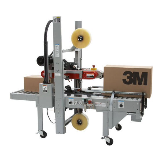
The 700rks is adjustable to a wide range of box sizes (see "Specifi cations Section – Box Weight and Size Capacities"). 3M-Matic 700rks Random Case Sealer, Type 40800 Note – Shown above is the lower tape supply roll and bracket assembly in the alternate location. 2010 January... -
Page 14: How To Read And Use The Manual
- Instructions and notes on the machine electric diagrams, warranty information, disposal a - Enclosures, drawings and diagrams defi nition of symbols, plus a parts list of the 3M- - Spare parts (last section) Matic 700rks Random case sealer 3M Industrial Adhesives and Tapes Division 3M Center, Bldg. -
Page 15: General Information
2-GENERAL INFORMATION 2.1 Data Identifying Manufacturer and Machine 2.2 Data for Technical Assistance and Service 2010 January 700rks-NA... -
Page 16: Warranty / Contents
3M’s factory or an authorized service station designated by 3M. A part will be presumed to have become defective after its warranty period unless the part is received or 3M is notifi ed of the problem no later than fi... -
Page 17: Safety
3-SAFETY 3.2 Explanation of Signal Word and 3.1 General Safety Information Possible Consequences Read all the instructions carefully before starting work with the machine; please pay particular atten- tion to sections marked by the symbol: This safety alert symbol identifi es important messages in this manual. -
Page 18: Table Of Warnings
3-SAFETY (continued) 3.3 Table of Warnings WARNING • To reduce the risk associated with mechanical and electrical hazards: − Read, understand, and follow all safety and operating instructions before operating or servicing the case sealer. Figure 3-2 − Allow only properly trained and qualifi... - Page 19 3-SAFETY (continued) WARNING • To reduce the risk associated with sharp blade hazards: − Keep hands and fi ngers away from WARNING tape cutoff blades under orange blade Sharp Blade guards. The blades are extremely sharp. IMPORTANT! Tape cutting blade. Never remove the safety device which covers the blade on the top and bottom taping units.
-
Page 20: Operator's Qualifi Cations Defi Nition
3-SAFETY (continued) 3.4 Operator's Qualifi cations WARNING - Machine Operator - Mechanical Maintenance Technician • To reduce the risk associated with - Electrical Maintenance Technician mechanical and electrical hazards: - Manufacturer’s Technician/Specialist − Read, understand, and follow all safety (See Section 3.11) and operating instructions before operating or servicing the case sealer. -
Page 21: Operator's Required Skill Levels
3-SAFETY (continued) Skill 2a: Electrical Maintenance Technician 3.11 Operator's Skill Levels Required to Perform This operator is trained to use the machine as the the Main Operations on the Machine MACHINE OPERATOR and in addition is able to: • Work with the safety protection disconnected The Table shows the minimum operator's skill for •... -
Page 22: Component Locations
3-SAFETY (continued) 3.12 Component Locations Refer to Figure 3-9 below to acquaint yourself with the various components and controls of the case sealer. Also refer to Section 7 for controls, valves, and switch locations and Manual 2 for taping head components. Column Guards Upper Drive Belt Covers and Belts... -
Page 23: Table Of Warnings And Replacement Labels
Important Safeguards (continued) 78-8113-6769-3 78-8070-1421-8 (2) 78-8062-4266-1 78-8068-3859-1 78-8070-1329-3 78-8111-1496-2 78-8113-6750-3 Figure 1-1 – Replacement Labels/3M Part Numbers 2010 January 700rks... - Page 24 Important Safeguards (continued) 78-8095-1141-9 78-8070-1328-5 78-8070-1319-4 78-8098-8908-8 Box Centering Switch 78-8070-1360-8 78-8070-1336-8 (2) Figure 1-2 – Replacement Labels/3M Part Numbers 2010 January 700rks...
- Page 25 Important Safeguards (continued) 78-8113-6768-5 78-8113-6768-5 78-8113-6717-2 78-8070-1332-7 78-8052-6680-2 (4) 78-8070-1333-5 Leg Height Adjustment Label (Not shown) 78-8070-1339-2 (2) 3M Logo (Each side of upper 78-8070-1317-8 assembly - Not shown) Figure 1-3 – Replacement Labels/3M Part Numbers 2010 January 700rks...
-
Page 26: Power Requirements
A pressure regulator/fi lter is included The machine is equipped with a 2.4m [8 foot] standard neoprene covered power cord and a grounded plug. Contact your 3M Representative for power requirements not listed above. 2. Operating Rate Box drive belt speed is approximately 0.5 m/s [100 feet per minute]. -
Page 27: Tape Roll Diameter
4-SPECIFICATIONS (continued) Specifi cations 6. Tape Roll Diameter Up to 405 mm [16 inch] maximum on a 76.2mm [3 inch] diameter core. (Accommodates all system roll lengths of Scotch ® fi lm tapes.) 7. Tape Application Leg Length – Standard 70mm ±... -
Page 28: Box Weight And Size Capacities
Note: Length of boxes in illustrations above are not to scale. Special modifi cations may be available for carton sizes not listed on previous page. Contact your 3M Representative for information. Note: The case sealer can accommodate most boxes within the size range listed above. However, if the box length (in direction of seal) to box height ratio is .6 or less, then several boxes should be... -
Page 29: Machine Noise Levels
4-SPECIFICATIONS (continued) 10. Machine Dimensions: Minimum 1180 1575 610*** 1640 [Inches] [36.5] [40 .5] [62] [18] [24] [4.75] [30.38] [64.5] Maximum 2185*** [Inches] [86] [35] Weight - 225 kg [500 pounds] crated (approximate) 200 kg [430 pounds] uncrated (approximate) Machine Noise Level: 78dB with tape roll inserted. - Page 30 THIS PAGE IS BLANK...
-
Page 31: Handling And Transportation Of Uncrated Machine
5-SHIPMENT-HANDLING-STORAGE, TRANSPORT 5.1 Shipment and Handling of Packed Machine - The machine is fi xed on the pallet with four (4) bolts and can be lifted by using a fork truck. - The package is suitable to travel by land and by air. - Optional sea freight package is available. -
Page 32: Unpacking
6-UNPACKING 6.1 Uncrating Removal of Pallet The envelope attached to the shipping box contains Loosen and remove nuts and brackets using the the uncrating instructions of the machine (Figure 6-1). open end spanner supplied in the tool box (Figure 6-4). Figure 6-4 Figure 6-1 A cardboard box is located under the machine body. -
Page 33: Installation
7-INSTALLATION 7.1 Operating Conditions WARNING The machine should operate in a dry and relatively clean environment (See Specifi cations). • To reduce the risk associated with muscle strain: 7.2 Space Requirements for Machine Operation − Use the appropriate rigging and material and Maintenance Work handling equipment when lifting or Minimum distance from wall (Figure 7-1):... -
Page 34: Assembly Completion / Machine Set-Up
7-INSTALLATION (continued) 7.5 Removal of Plastic Ties Cut the plastic which attaches the top head to the frame and remove the polystyrene blocks (Figure 7-4). Cut the plastic strap which attaches the strip and the EMERGENCY STOP cable to the frame (Figure 7-5). Figure 7-4 Figure 7-6 7.6 Assembly Completion / Machine Set-up... - Page 35 7-INSTALLATION (continued) Machine Set-Up The following instructions are presented in the Note – A precision regulator is used to balance the order recommended for setting up and installing the top drive assembly. Due to the self relieving case sealer, as well as for learning the operating feature of this regulator a small amount of air functions and adjustments.
- Page 36 7-INSTALLATION AND SET-UP (continued) Column Guards Buffi ng Cable Roller Note: Column Guards are removed before Installing the Bumper Supports (see Figure 2-6 and Figure 6-1). Column Guards are then reinstalled (as shown in a ro- tated 180° position) Figure 7-7 – 700rks Frame Set-Up 7.
-
Page 37: Infeed Conveyor Assembly
7-INSTALLATION AND SET-UP (continued) 7.7 Infeed Conveyor Assembly 1. Remove the conveyor and the package of parts from the carton. 2. Verify that the package contains two right angled cover plates, twelve (12) M8 x 15 hex head screws, and eight (8) M8 fl at washers. 3. -
Page 38: Bumper Supports
These events can potentially cause damage to the machine. For more information on bumper settings, contact • To reduce the risk associated with your 3M service representative. hazardous voltage: − Position electrical cord away from foot and/or vehicle traffi c Note - Machines outside the U.S. - Page 39 7-INSTALLATION AND SET-UP (continued) 7.15 Controls, Valves, and Switch Locations Refer to Figure 7-13 below to acquaint yourself with the various components and controls of the case sealer. Also see component locations in Section 3 and Section II for taping head components. Note: Indicator, Function of these...
- Page 40 7-INSTALLATION AND SET-UP (Continued) Pressure Regulator regulates main air pressure to the machine to adjust pressure, pull knob up and turn – push down to lock setting. Filter removes dirt and moisture from plant air before it enters the case sealer pneumatic circuits.
-
Page 41: Tape Loading / Threading
7-INSTALLATION AND SET-UP (continued) For boxes which are fully packed with products that support the top fl aps, the adjustment of this regulator is not critical since the boxes can support the pressure of the upper frame (drive belts) at a wide range of regulator settings. However, if under-fi... -
Page 42: Box Sealing
7-INSTALLATION AND SET-UP (continued) 3. Once the box is pushed under the upper taping Box Centering Switch head, the upper drive assembly raising switch is released causing the upper drive assembly to descend onto the box top, as shown in Figure 7-20, allowing the drive belts to convey the box through the upper and lower taping heads for application of the tape seals. -
Page 43: Outboard Tape Roll Holder
7-INSTALLATION AND SET-UP (continued) 7.19 Completion of Taping Heads One Way See Manual 2 for Complete Instructions: Tension Roller 1. Place the Upper Taping Head in a convenient working position Tension 2. Use Figure 7-21 and tape threading label. Wrap Position the tape supply roll so the adhesive Roller side of tape is facing the front of the taping head... -
Page 44: Theory Of Operation
8-THEORY OF OPERATION 8.1 Description of the Working Cycle After having closed the top fl aps of the carton, the operator pushes it under the top infeed end in order to avoid the opening of the top fl aps. Further push- ing causes the two top and bottom belts to drive the box through the taping heads which automatically seal the top and bottom seams. -
Page 45: Controls
9-CONTROLS (continued) 9.1 Electrical/Drive Belt On/Off Switch Figure 9-1 9.2 Latching Emergency Stop Button Figure 9-2 Up to Figure 9-3 Adjust Down to Lock 9.3 Main Air On-Off Valve-Regulator-Filter Air On/Off Valve Regulator Air Supply Connector Filter 700rks-NA 2010 January... -
Page 46: Upper Drive Raising Switch
9-CONTROLS (continued) Pneumatic Valve Drive Assembly Raising Switch 9.4 Upper Drive Raising Switch Figure 9-4 9.5 Air Pressure Regulator / Top Drive Force Adjustment Locking Nut Figure 9-5 Upper Drive Actuator Switch 9.6 Upper Drive Assembly Actuator Switch Figure 9-6 2010 January 700rks-NA... -
Page 47: Box Conveying / Tape Seat Application
9-CONTROLS (continued) 9.7 Box Conveying / Tape Seal Application Figure 9-7 2010 January 700rks-NA... -
Page 48: Blade Guards
10-SAFETY DEVICES OF THE MACHINE 10.1 Blade Guards 10.3 Electric System Both the top and bottom taping units have a blade guard. (See Manual 2: AccuGlide™ 3 Taping The electric system is protected by a ground wire Heads - 3 Inch). whose continuity has been tested during the fi... -
Page 49: Set-Up And Adjustments
11 - SET UP AND ADJUSTMENTS 11.1 Box Width Adjustment Upper Drive Figure 11-2 Boxes are automatically centered by the Side Actuator Switch Guides (Figure 11-1). The Side Guides are trig- gered by the Centering Guide Switch which is lo- cated on the machine bed. - Page 50 11 - SET UP AND ADJUSTMENTS (continued) 11.5 Run Boxes to Inspect Adjustment (Figure 11-5) Important: Before starting the machine, verify that no tools or other objects are on the conveyor bed. Turn electrical and air pressure switches to On. This starts the drive belts and engages the pneumatic air pressure system.
-
Page 51: Operation
12-OPERATION 12.1 Operator's Correct Working Position and 12.3 Starting Production Operational Flow (Figure 12-1). Let the machine run without cartons and check its safety devices. Then start the working cycle. 12.4 Tape Replacement and Threading WARNING • To reduce the risk associated with sharp blade hazards: −... -
Page 52: Troubleshooting
Troubleshooting The Troubleshooting Guide lists some possible machine problems, causes and corrections. Also see Manual 2 "Troubleshooting" for taping head problems. 12.9 Troubleshooting Guide Correction Problem Cause Drive belts do not convey boxes Check machine specifi cations. Narrow boxes Boxes are narrower than recommended, causing slippage and premature belt wear. - Page 53 Troubleshooting (continued) Troubleshooting Guide Problem Cause Correction Upper drive assembly does not Lower air pressure Disconnect the air supply. Make move up or moves up slowly sure main pressure regulator reads zero. Reconnect air supply and adjust regulator to read 70 PSIG [5 bar].
-
Page 54: Safety Measures (See Section 3)
13-MAINTENANCE AND REPAIRS 13.1 Safety Measures (see section 3) 13.2 Tools and Spare Parts Supplied with the Machine Carrying out maintenance and repairs may imply the necessity to work in dangerous situations. See Spare Parts Order Section. 13.3 Recommended Frequency of Inspection and Maintenance Operations Operation Frequency Qualifi... - Page 55 • To reduce the risk associated with impact hazards: − Always use appropriate supporting means when working under the upper drive assembly 13.8 Box Drive Belt Replacement Note – 3M recommends the replacement of drive belts in pairs, especially if belts are unevenly worn. Lower Drive Belts Figure 13-4 1.
-
Page 56: Drive Pulley Ring
13-MAINTENANCE AND REPAIRS (continued) 13.9 Drive Pulley Rings Before installing a new belt, check the orange plastic drive pulley rings for wear. If torn, broken, or worn smooth, replace the rings (Figure 13-6). Figure 13-6 WARNING • To reduce the risk associated with mechanical and electrical hazards: −... - Page 57 Adjustments (continued) WARNING • To reduce the risk associated with mechanical and electrical hazards: − Turn electrical and air supply off and disconnect before performing any adjustments, maintenance or servicing the machine or taping heads Refer to Figure 13-8 and 13-9 and adjust belt tension as follows: 1.
- Page 58 Adjustments (continued) WARNING • To reduce the risk associated with mechanical and electrical hazards: − Turn electrical and air supply off and disconnect before performing any adjustments, maintenance or servicing the machine or taping heads M5 x 10 Screw (4) Front Cover Belt Tension Screw, M8...
- Page 59 2) Create added stress to the bumper. 3) Cause a malfunction of the machine. These events can potentially cause damage to the machine. For more information on bumper settings, contact your 3M service representative. Safety Guard (Shown is after Safety...
- Page 60 Special Set-Up Procedure (continued) WARNING • To reduce the risk associated with mechanical and electrical hazards: − Turn electrical and air supply off and disconnect before performing any adjustments, maintenance or servicing the machine or taping heads Box and Machine Bed Height Range – Refer to Figure 13-11 Moving the outer columns up one set of mounting holes increases the maximum box size handled by the 700rks case sealer and decreases the minimum machine bed height.
- Page 61 Special Set-Up Procedure (continued) WARNING • To reduce the risk associated with mechanical and electrical hazards: − Turn electrical and air supply off and disconnect before performing any adjustments, maintenance or servicing the machine or taping heads − Allow only properly trained and qualifi ed personnel to operate and/or service this equipment Box Height Range –...
- Page 62 THIS PAGE IS BLANK...
- Page 63 13-MAINTENANCE AND REPAIRS (continued) 13.12 List of the Maintenance Operations Date: Description of Operation ________ ________________________________________________________________ ________ ________________________________________________________________ ________ ________________________________________________________________ ________ ________________________________________________________________ ________ ________________________________________________________________ ________ ________________________________________________________________ ________ ________________________________________________________________ ________ ________________________________________________________________ ________ ________________________________________________________________ ________ ________________________________________________________________ ________ ________________________________________________________________ ________ ________________________________________________________________ ________ ________________________________________________________________ ________ ________________________________________________________________ ________...
- Page 64 THIS PAGE IS BLANK...
-
Page 65: Statement Of Conformity
14-ADDITIONAL INSTRUCTIONS 15-ENCLOSURES / SPECIAL INFO. 14.1 Information for Disposal of Machine The machine is composed of the following materials: - Steel structure - Nylon rollers - Drive belts in PVC - Nylon pulleys For machine disposal, follow the regulations published in each country. -
Page 66: Electric Diagrams
16-TECHNICAL DIAGRAMS 16.1 Electric Diagram 2010 January 700rks-NA... -
Page 67: Pneumatic Diagrams
16-TECHNICAL DIAGRAMS (continued) 16.2 Pneumatic Diagram WARNING • To reduce the risk associated with mechanical and electrical hazards: − Turn electrical and air supply off and disconnect before performing any adjustments, maintenance or servicing the machine or taping heads 2010 January 700rks-NA... - Page 68 THIS PAGE IS BLANK...
- Page 69 16-TECHNICAL DOCUMENTATION AND INFORMATION (continued) 16.3 Spare Parts Order The following parts are normal wear items and should be ordered and kept on hand as used. Qty. Part Number Description 78-8070-1531-4 Belt – Drive W/Pin In addition, a tool/spare parts kit supplied with the 700rks Random Case Sealer contains the following spare parts: Qty.
- Page 70 THIS PAGE IS BLANK...
- Page 71 Important – Not all the parts listed are normally stocked items. Some parts or assemblies shown are available only on special order. Contact 3M/Tape Dispenser Parts to confi rm item availability. Options and Accessories For additional information on the options and accessories listed below, contact your 3M Representative.
- Page 72 THIS PAGE IS BLANK...
- Page 73 700rks Figure 15031 Figure 15266 Figure 15249 Figure 15267 Figure 15265 Figure 15269 Figure 15263 Figure 15310 Infeed/Exit Figure 15264 Figure 15262 Conveyor Frame Assemblies Frame Assemblies 2010 January 700rks-NA...
- Page 74 700rks 13 12 21 14 Figure 10531 2010 January 700rks-NA...
- Page 75 700rks Figure 15031 Ref. No. 3M Part No. Description 15031-1 78-8137-1157-5 Tape Roll Bracket Assembly 15031-2 78-8137-1158-3 Tape Drum Bracket Assembly 15031-3 78-8070-1566-0 Bracket – Tape Drum 15031-4 78-8070-1395-4 Bracket – Bushing Assembly 15031-5 78-8070-1568-6 Cap – Bracket 15031-6 78-8060-8462-6 Shaft –...
- Page 76 700rks 0 25 Optional Figure 15262 2010 January 700rks-NA...
- Page 77 700rks Figure 15262 Ref. No. 3M Part No. Description 15262-1 78-8137-0975-1 Conveyor Bed Assembly 15262-2 78-8137-0976-9 Bed – Conveyor 15262-3 78-8137-0577-5 Support – Drive 15262-4 26-1003-5842-8 Screw – Hex Hd, M8 x 20 15262-5 78-8017-9318-9 Washer – Plain, 8 mm...
- Page 78 700rks 12 = G Figure 15263 2010 January 700rks-NA...
- Page 79 700rks Figure 15263 Figure 15263 Ref. No. 3M Part No. Description 15263-1 78-8076-4663-9 Cylinder – Air /32 x 580 + 20 15263-2 78-8094-6457-7 Cap – 1/8 Inch 15263-3 78-8091-0313-4 Elbow – 3199.08.10 15263-4 78-8076-4680-3 Screw – Cushioning, Cyl/32 15263-5 78-8060-8091-3 Valve –...
- Page 80 700rks Figure 15264 2010 January 700rks-NA...
- Page 81 700rks Figure 15264 Ref. No. 3M Part No. Description 15264-1 78-8094-6379-3 Support – Box 15264-2 78-8113-6759-4 Box – W/English Language Label 15264-3 78-8094-6381-9 Screw – Soc Hd, Hex Hd, M4 x 15 15264-4 78-8005-5740-3 Washer – Plain, 4 mm 15264-5 26-1003-6914-4 Nut –...
- Page 82 700rks 51 49 Should point to the support of the motor Figure 15265/1 2010 January 700rks-NA...
- Page 83 700rks Figure 15265/1 Ref. No. 3M Part No. Description 15265-1 78-8137-0978-5 Bottom Drive Assy - w/Motor 15265-2 78-8137-0579-1 Frame - Drive 15265-3 78-8137-0568-4 Spacer 15265-4 26-1003-5829-5 Screw Hex Hd. M6 X 12 15265-7 78-8052-6710-7 Roller - Idler 15265-8 78-8052-6709-9 Washer - Special...
- Page 84 700rks Figure 15265/2 2010 January 700rks-NA...
- Page 85 700rks Figure 15265/2 Ref. No. 3M Part No. Description 15265-35 78-8054-8984-2 Bushing 15265-36 78-8070-1529-8 Support - Shaft 15265-37 78-8070-1530-6 Radial Ball Bearing - 6205-2RS, O.D. 52 15265-38 78-8057-5739-6 Key, M5 X5 X 30MM 15265-39 78-8076-5105-0 Pulley Assy - Drive 15265-40...
- Page 86 These events can potentially cause damage to the machine. Figure 15266 * NOTE - IMPORTANT: Parts #40 & 41 are for "NORMAL" Position. For more information on bumper settings, contact your 3M service representative. Remove #40 & 41 and replace with #42 when Column is in "RAISED" Position.
- Page 87 700rks Figure 15266 Ref. No. 3M Part No. Description 15266-1 78-8137-0981-9 Column - Outer 15266-2 78-8076-4540-9 Pin - Air Cylinder 15266-3 78-8060-8035-0 E-Ring 7DIN6799 15266-4 78-8054-8821-6 End - Cap 15266-5 26-1003-7964-8 Screw Soc. Hd. Hex M8 X 20 15266-6 78-8137-0924-9...
- Page 88 700rks Figure 15267/1 2010 January 700rks-NA...
- Page 89 700rks Figure 15267/1 Ref. No. 3M Part No. Description 15267-1 78-8137-0988-4 Top Drive Assy 15267-2 78-8137-0968-6 Frame Drive - Upper 15267-3 78-8070-1520-7 Guide - Drive Belt 15267-4 26-1005-4757-4 Screw - Flat Hd, Soc. Dr. M5 X 20 15267-5 78-8137-0533-8 Clamp - Upper Head...
- Page 90 700rks Random Case Sealer 700rks This item does not point Figure 15267/2 to a Shaft - Roller 2010 January 700rks...
- Page 91 700rks Figure 15267/2 Ref. No. 3M Part No. Description 15267-45 26-1003-5842-8 Screw Hd.M8 X 20 15267-46 78-8137-0961-1 Gear Motor 115V 60Hz 78-8100-0865-2 Motor - 220/220v, 50/60 Hz, 3 Phase 78-8052-6718-0 Motor - 220/415v, 50 Hz, 3 Phase 78-8052-6719-8 Motor - 260/440v, 50 Hz, 3 Phase 78-8046-8267-8 Motor - 110/110v, 50/60 Hz, 1 Phase 0.12kw...
- Page 92 700rks Random Case Sealer 700rks Figure 15249 2010 January 700rks...
- Page 93 700rks Figure 15249 Ref. No. 3M Part No. Description 15249-1 78-8091-0660-8 Housing – Wire 15249-2 78-8076-4702-5 Grommet – /28 15249-3 26-1003-7963-0 Screw – Soc Hd M8 x 16 15249-5 78-8010-7163-6 Screw – Hex Hd M5 x 10 15249-6 78-8005-5741-1 Washer – Plain M5...
- Page 94 700rks Random Case Sealer 700rks 30 23 12 34 26 Figure 15269 2010 January 700rks...
- Page 95 700rks Figure 15269 Ref. No. 3M Part No. Description 15269-1 78-8137-0990-0 Infeed Conveyor Assembly 15269-2 78-8137-0991-8 Frame – Infeed 15269-3 78-8137-0992-6 Frame 15269-4 78-8076-4518-5 Spacer – Bearing 15269-5 78-8023-2551-0 Bearing – 6005-2RS 15269-6 78-8076-4567-2 Pivot – Infeed 15269-7 78-8076-4568-0 Key – 7 x 8 x 25...
- Page 96 700rks Random Case Sealer 700rks Figure 15310 2010 January 700rks...
- Page 97 700rks Figure 15310 Ref. No. 3M Part No. Description 15310-1 78-8137-3529-3 Conveyor In/Exit 700rks/rks Type 40800 15310-2 78-8076-4509-4 Frame - R/H 15310-3 78-8076-4510-2 Frame - L/H 15310-4 78-8076-4511-0 Cap - Front, R/H 15310-5 78-8076-4512-8 Cap - Front, L/H 15310-6 78-8032-0375-7...
- Page 98 THIS PAGE IS BLANK...
-
Page 99: Spare Parts / Ordering
_____________________________________ For reference, record taping head(s) serial number(s) here. AccuGlide ™ is a Trademark of 3M Industrial Adhesives and Tapes 3M, St. Paul, MN 55144-1000 3M Center, Building 220-5E-06 Litho in U.S.A St. Paul, MN 55144-1000 © 3M 2009 44-0009-2071-8 (A022009) - Page 101 Included with each machine is an Instructions and Parts List manual. Technical Assistance / Replacement Parts and Additional Manuals: Call the 3M-Matic™ Help line at 1-800 328-1390. Provide the customer support coordinator with the model/machine name, machine type, and serial number that are located on the identifi...
- Page 102 THIS PAGE IS BLANK...
- Page 103 ™ and Scotch ™ are Trade- 3M Industrial Adhesives and Tapes marks of 3M, St. Paul, MN 55144-1000 3M Center, Building 220-5E-06 Printed in U.S.A. St. Paul, MN 55144-1000 © 3M 2009 44-0009-1852-2 (F031008) AccuGlide 3 Taping Head - 3"...
- Page 104 THIS PAGE IS BLANK...
- Page 105 Instruction Manual ™ AccuGlide Upper and Lower Taping Heads - 3 Inch Type 10800 Table of Contents Page Equipment Warranty and Limited Remedy ....................i - ii Table of Contents............................Equipment Warranty and Limited Remedy ....................Intended Use ............................Taping Head Contents / How to Use Manual.................... Important Safeguards ..........................
-
Page 106: Equipment Warranty And Limited Remedy
If any part is defective within this warranty period, your exclusive remedy and 3M’s and seller’s sole obligation shall be, at 3M’s option, to repair or replace the part. 3M must receive actual notice of any alleged defect within a reasonable time after it is discovered, but in no event shall 3M have any obligation under this warranty unless it receives such notice within fi... -
Page 107: Intended Use
Scotch ® pressure-sensitive fi lm box sealing tape other than 3M-Matic™ case sealers. This includes to the top and/or bottom center seam of regular replacement of other types of taping, gluing or slotted containers. - Page 108 THIS PAGE IS BLANK...
-
Page 109: Taping Head Contents / How To Use Manual
(ELV), a glossary with a defi nition of symbols, plus a parts list 3M Industrial Adhesives and Tapes Division 3M Center, Bldg. 220-5E-06 St. Paul, MN 55144-1000 (USA) Edition February 2009/Copyright 3M 2009. All rights reserved The manufacturer reserves the right to change the product at any time without notice Publication ©... -
Page 110: Important Safeguards
Important Safeguards This safety alert symbol identifi es CAUTION important safety messages in this manual. READ AND UNDERSTAND • THEM BEFORE INSTALLING OR To reduce the risk associated with OPERATING THIS EQUIPMENT. muscle strain: − Use proper body mechanics when removing or installing taping heads that are moderately heavy or may be considered Explanation of Signal Word Consequences... - Page 111 Important – In the event the following safety labels are damaged or destroyed, they must be replaced to ensure operator safety. See "Replacement Parts Illustrations and Parts Lists" for label part numbers. Upper Taping Head Label 78-8137-3317-3 Lower Taping Head Label 78-8137-3316-5 78-8070-1335-0 Figure 1-1 Replacement Labels/3M Part Numbers 2009 February AccuGlide 3 Taping Head - 3"...
-
Page 112: Specifi Cations
90mm [3-1/2 inches] (with optional 2 inch leg length) Width – 150mm [6 inches] When upper and lower taping heads are used on “3M-Matic” case sealers, refer to the respective instruction manual specifi cations for box weight and size capacities. Operating Rate: Conveyor speeds up to 0.5 m/s [100 feet per minute]. -
Page 113: Dimensional Drawing
Specifi cations (Continued) 132mm [5.2 in.] Figure 2-1 – Dimensional Drawing 2009 February AccuGlide 3 Taping Head - 3"... -
Page 114: Installation
70mm [2-3/4 inches], the taping heads evident, fi le a damage claim immediately with the must be completely staggered so only one tape transportation company and also notify your 3M seal is being applied at one time. Representative. -
Page 115: Operation
Operation Figure 3-1 Taping Head Components/Threading Diagram - Upper Head (Left Side) View) Applying Roller Orange Knife Guard Tape Cut-Off Knife Threading Needle Wrap Roller Buffi ng Roller Buffi ng Arm Cover Knurled Roller Applying Tension Wrap Roller Mechanism Spring One-Way Tension Roller Tape Adhesive Side... -
Page 116: Tape Loading - Upper Taping Head
Operation (Continued) WARNING • To reduce the risk associated with shear, pinch, and entanglement hazards: − Turn air and electrical supplies off on associated equipment before performing any adjustments, maintenance, or servicing the machine or taping heads − Never attempt to work on the taping heads or load tape when the box drive system is running •... - Page 117 Operation (Continued) Figure 3-4 Place tape roll on tape drum to dispense tape with adhesive side forward. Seat tape roll fully against back fl ange of drum. Adhere tape lead end to threading needle as shown. WARNING • To reduce the risk associated with sharp Figure 3-4 –...
-
Page 118: Maintenance
Maintenance WARNING • To reduce the risk associated with shear, pinch, and entanglement hazards: − Turn air and electrical supplies off on associated equipment before performing any adjustments, maintenance, or servicing the taping heads − Never attempt to work on the taping head or load tape while the box drive system is running •... -
Page 119: Cleaning
Maintenance (Continued) WARNING • To reduce the risk associated with shear, pinch, and entanglement hazards: − Turn air and electrical supplies off on associated equipment before performing any adjustments, maintenance, or servicing the taping heads − Never attempt to work on the taping head or load tape while the box drive system is running •... -
Page 120: Adjustments
Adjustments WARNING • To reduce the risk associated with shear, pinch, and entanglement hazards: − Turn air and electrical supplies off on associated equipment before performing any adjustments, maintenance, or servicing the machine or taping heads − Never attempt to work on the taping head or load tape while the box drive system is running Figure 5-1 –... -
Page 121: Applying Mechanism Spring
Adjustments (Continued) WARNING • To reduce the risk associated with shear, pinch, and entanglement hazards: − Turn air and electrical supplies off on associated equipment before performing any adjustments, maintenance, or servicing the machine or taping heads − Never attempt to work on the taping head or load tape while the box drive system is running Applying Mechanism Spring... -
Page 122: Leading Tape Leg Length Adjustment
Adjustments (Continued) WARNING • To reduce the risk associated with shear, One-Way pinch, and entanglement hazards: Tension − Turn air and electrical supplies off on Roller associated equipment before performing any adjustments, maintenance, or servicing the machine or taping heads −... - Page 123 Troubleshooting Troubleshooting Guide Cause Correction Problem The tape is threaded incorrectly The tape must go around the wrap The tape leg on the front of the roller before going around the case is too long one-way tension roller The tape tension is too low Adjust the one-way tension roller The knurled roller drags Check for adhesive build-up...
-
Page 124: Troubleshooting
Troubleshooting (Continued) Troubleshooting Guide Cause Correction Problem There is excess tension on the Adjust the one-way tension roller Tape is tabbing on the trailing leg tape drum assembly and/or the and/or the tape drum assembly on the back of the box one-way tension roller assembly Rollers in the tape path do not Clean adhesive deposits from... -
Page 125: Spare Parts/Service Information
Spare Parts/Service Information Recommended Spare Parts Listed are a set of spare parts that will periodically require replacement due to normal wear. These parts should be ordered to keep the taping heads in production: AccuGlide™ 3 Upper Taping Head - 3 Inch Qty. -
Page 126: Replacement Parts Illustrations And Parts List
Refer to the fi rst page of this instruction manual "Replacement Parts and Service Information" for replacement parts ordering information. IMPORTANT – Not all the parts listed are normally stocked items. Some parts or assemblies shown are available only on a special order basis. Contact 3M/Tape Dispenser Parts to confi rm item availability. 2009 February... - Page 127 ™ Taping Head Assemblies - AccuGlide 3 Taping Heads - 3 Inch Figure 10402 Figure 10932 (Upper) Figure 10931 (Lower) Figure 10930 Figure 10929 Figure 10926 (Upper) Figure 10927 (Lower) Figure 10928 2009 February AccuGlide 3 Taping Head - 3"...
- Page 128 17 18 Figure 10932 – Upper Head 2009 February AccuGlide 3 Taping Head - 3"...
- Page 129 Figure 10932 – Upper Head Ref. No. 3M Part No. Description 10932-1 78-8137-3294-4 Frame – Tape Mount Upper Assembly 10932-2 78-8137-3295-1 Frame – Front Upper Assembly 10932-3 78-8068-4143-9 Guide – #1 10932-4 78-8068-4144-7 Guide – #2 10932-5 78-8060-7818-0 Screw – Hex Hd, M4 x 12...
- Page 130 12 11 Figure 10929 – Upper and Lower Heads 2009 February AccuGlide 3 Taping Head - 3"...
- Page 131 Figure 10929 – Upper and Lower Heads Ref. No. 3M Part No. Description 10929-1 78-8133-9520-5 Arm – Applying, R/H 10929-2 78-8133-9521-3 Arm – Applying, L/H 10929-3 78-8070-1292-3 Plate – Back-Up 10929-4 78-8076-4736-3 Shaft Roller 10929-5 78-8076-4737-1 Roller Assembly – Knurled...
- Page 132 Figure 10926 – Upper Head 2009 February AccuGlide 3 Taping Head - 3"...
- Page 133 Figure 10926 – Upper Head Ref. No. 3M Part No. Description 10926-1 78-8137-3300-9 Buffi ng Arm – Sub Assembly 10926-2 78-8137-3301-7 Buffi ng Arm – Sub Assembly 10926-3 78-8091-0799-4 Shaft – 10 x 85, W/Hexagon 10926-4 78-8137-1397-7 Roller – Buffi ng Assembly...
- Page 134 Figure 10930 – Upper and Lower Heads AccuGlide 3 Taping Head - 3" 2009 February...
- Page 135 Figure 10930 – Upper and Lower Heads Ref. No. 3M Part No. Description 10930-1 78-8137-3302-5 Link – R/H Assembly 10930-3 78-8137-3314-0 Shaft – Pivot, Buffi ng 10930-4 78-8017-9082-1 Bearing – Special 30 mm 10930-5 78-8017-9106-8 Screw – Bearing Shoulder 10930-6 26-1003-5829-5 Screw –...
- Page 136 Figure 10928 – Upper and Lower Heads 2009 February AccuGlide 3 Taping Head - 3"...
- Page 137 Figure 10928 – 3" Upper and Lower Heads Ref. No. 3M Part No. Description 10928-1 78-8070-1283-2 Frame – Cut-Off 10928-2 78-8028-7899-7 Knife – 89 mm/3.5 Inch 10928-3 26-1002-5817-2 Screw – Hex Hd, M5 x 8 10928-4 78-8076-4741-3 Knife Guard Assembly – W/English Language Label...
- Page 138 11 15 Figure 10402 – Upper and Lower Heads 2009 February AccuGlide 3 Taping Head - 3"...
- Page 139 Figure 10402 – 3" Latch Upper and Lower Heads Ref. No. 3M Part No. Description 10402-1 78-8070-1395-4 Bracket – Bushing Assembly 10402-2 78-8060-8462-6 Shaft – Tape Drum, 3 Inch Head 10402-3 78-8017-9169-6 Nut – M18 x 1 10402-4 78-8098-8829-6 Tape Drum Sub Assembly – 3 Inch Wide...
- Page 140 Figure 10931 – Lower Head 2009 February AccuGlide 3 Taping Head - 3"...
- Page 141 Figure 10931 – Lower Head Ref. No. 3M Part No. Description 10931-1 78-8137-3296-9 Frame – Tape Mount Lower Assembly 10931-2 78-8137-3297-7 Frame – Front Lower Assembly 10931-3 78-8068-4144-7 Guide – #2 10931-4 78-8068-4143-9 Guide – #1 10931-5 83-0002-7336-3 Screw – Hex Hd, M4 x 14...
- Page 142 Figure 10927 – Lower Head 2009 February AccuGlide 3 Taping Head - 3"...
- Page 143 Figure 10927 – Lower Head Ref. No. 3M Part No. Description 10927-1 78-8137-3300-9 Buffi ng Arm – Sub Assembly 10927-2 78-8137-3301-7 Buffi ng Arm – Sub Assembly 10927-3 78-8091-0799-4 Shaft – 10 x 85, W/Hexagon 10927-4 78-8137-1397-7 Roller – Buffi ng...
- Page 144 THIS PAGE IS BLANK...
Need help?
Do you have a question about the 40800 and is the answer not in the manual?
Questions and answers