Table of Contents
Advertisement
Quick Links
Instructions and Parts List
3M-Matic
800af
Type 39600
Adjustable
Case Sealer
with
AccuGlide
Taping Heads
Serial No.
For reference, record machine serial number here.
3M Industrial Adhesives and Tapes
3M Center, Building 220-5E-06
St. Paul, MN 55144-1000
™
™
2+
1
Important Safety
Information
BEFORE INSTALLING
OR OPERATING THIS
EQUIPMENT
Read, understand, and
follow all safety and
operating instructions.
Spare Parts
It is recommended you
immediately order the
spare parts listed in the
"Spare Parts/Service
Information" section.
These parts are expected
to wear through normal
use, and should be kept
on hand to minimize
production delays.
"3M-Matic"and "AccuGlide" are Trademarks of,
3M St. Paul, MN 55144-1000
Printed in U.S.A.
© 3M 2010 44-0009-1931-4 (B123010-NA)
Advertisement
Table of Contents

Related Manuals for 3M 3M-Matic AccuGlide 2+ 800af


Summary of Contents for 3M 3M-Matic AccuGlide 2+ 800af
- Page 1 For reference, record machine serial number here. on hand to minimize production delays. "3M-Matic"and "AccuGlide" are Trademarks of, 3M Industrial Adhesives and Tapes 3M St. Paul, MN 55144-1000 3M Center, Building 220-5E-06 Printed in U.S.A.
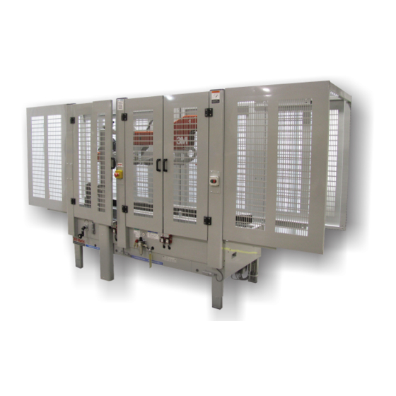
- Page 2 800af-NA Adjustable case sealer. 3M-Matic 3M Industrial Adhesives and Tapes 3M Center, Building 220-5E-06 St. Paul, MN 55144-1000 Edition December 2010 Copyright 3M 2010...
-
Page 3: Replacement Parts And Service Information
For Commercial Use Only 3M-Matic , AccuGlide and Scotch are Trademarks of ™ ™ ™ 3M Industrial Adhesives and Tapes 3M St. Paul, MN 55144-1000 3M Center, Building 220-5E-06 Printed in U.S.A. St. Paul, MN 55144-1000 © 3M 2010 44-0009-1851-4 (H031008-NA) - Page 4 THIS PAGE IS BLANK...
-
Page 5: Table Of Contents
TABLE OF CONTENTS - MANUAL 1: 800af Adjustable Case Sealer (For Taping Head Information - See MANUAL 2: AccuGlide™ 2+ Taping Heads - 2 inch) 800af Adjustable Case Sealer Page Cover Page Replacement Parts and Service Information ................ i - ii Table of Contents ......................... - Page 6 THIS PAGE IS BLANK...
- Page 7 TABLE OF CONTENTS (continued) 5. Shipment, Handling, and Storage 5.1 Packed Machine Shipment and Handling ................17 5.2 Overseas Shipment Packaging (Optional) ................17 5.3 Handling and Transportation of Uncrated Machine ............. 17 5.4 Machine Storage ......................... 17 6. Unpacking 6.1 Uncrating ..........................
- Page 8 THIS PAGE IS BLANK...
- Page 9 TABLE OF CONTENTS (continued) 12. Maintenance 12.1 Cleaning ..........................36 12.2 Lubrication ......................... 36 12.3 Drive Belt Replacement / Tension Adjustment ..............36 - 38 12.4 Air Line Filter ........................39 12.5 Circuit breaker ........................39 13. Adjustments 13.1 Gate Operation ....................... 40 13.2 Drive Belt Tension ......................
- Page 10 ABBREVIATIONS AND ACRONYMS LIST OF ABBREVIATIONS, ACRONYMS 3M-Matic - Trademark of 3M St. Paul, MN 55144-1000 Scotch - Trademark of 3M St. Paul, MN 55144-1000 Drw. - drawing - for example Fig. - exploded view fi gure no. (spare parts)
-
Page 11: Introduction
1.1 Manufacturing Specifi cations / Description / Intended Use The 3M-Matic™ 800af Adjustable Case Sealer with AccuGlide™ 2+ Taping Heads is to automatically seal the top and bottom center seams of regular slotted containers without the need for an operator. It will accept fi lled regular slotted containers from an existing conveyor, fold the top fl... -
Page 12: How To Read And Use The Manual
Bldg. 220-5E-06 St. Paul, MN 55144-1000 (USA) All pages and diagrams are numbered. The spare Edition December 2010 Copyright 3M 2010 All rights parts lists are identifi ed by the fi gure identifi cation reserved. The manufacturer reserves the right to number. -
Page 13: General Information
2-GENERAL INFORMATION 2.1 Data Identifying Manufacturer and Machine For Commercial Use Only 2010 December 800af-I-NA... -
Page 14: Warranty / Contents
3M’s factory or an authorized service station designated by 3M. A part will be presumed to have become defective after its warranty period unless the part is received or 3M is notifi ed of the problem no later than fi... -
Page 15: Safety
3-SAFETY 3.2 Explanation of Signal Word and 3.1 General Safety Information Possible Consequences Read all the instructions carefully before starting work with the machine; please pay particular atten- tion to sections marked by the symbol: This safety alert symbol identifi es important messages in this manual. -
Page 16: Table Of Warnings
3-SAFETY (continued) 3.3 Table of Warnings WARNING • To reduce the risk associated with mechanical and electrical hazards: − Read, understand, and follow all safety and operating instructions before operating or servicing the case seal Figure 3-2 − Allow only properly trained and qualifi... - Page 17 3-SAFETY (continued) WARNING • To reduce the risk associated with sharp blade hazards: − Keep hands and fi ngers away from WARNING tape cutoff blades under orange blade Sharp Blade guards. The blades are extremely sharp. IMPORTANT! Tape cutting blade. Never remove the safety device which covers the blade on the top and bottom taping units.
-
Page 18: Operator's Qualifi Cations Defi Nition
3-SAFETY (continued) 3.4 Operator's Qualifi cations WARNING - Machine Operator - Mechanical Maintenance Technician • To reduce the risk associated with - Electrical Maintenance Technician mechanical and electrical hazards: - Manufacturer’s Technician/Specialist − Read, understand, and follow all safety (See Section 3) and operating instructions before operating or servicing the case sealer. -
Page 19: Operator's Required Skill Levels
3-SAFETY (continued) Skill 2a: Electrical Maintenance Technician 3.11 Operator's Skill Levels Required to Perform This operator is trained to use the machine as the the Main Operations on the Machine MACHINE OPERATOR and in addition is able to: • Work with the safety protection disconnected The Table shows the minimum operator's skill for •... -
Page 20: Component Locations
3 - Important Safeguards 3.12 Component Locations Refer to Figure 3-9 below to acquaint yourself with the various components and controls of the case sealer. Also refer to Manual 2 for taping head components. Emergency Height Stop Upper Adjustment Switch Taping Handle Head... -
Page 21: Table Of Warnings And Replacement Labels
A label kit is available as a stock item or individual labels can be ordered (Figure 3-10). 78-8070-1366-5 78-8070-1336-8 78-8113-6882-4 78-8095-1141-9 78-8095-1628-8 STOP 78-8113-6883-2 78-8070-1330-1 78-8062-4266-1 78-8070-1339-2 78-8070-1366-5 78-8070-1331-9 3M Logo (not shown) 78-8060-8481-6 Leg Height Adjustment Label 78-8070-1329-3 (not shown) Figure 3-10 - Warning Labels 2010 December 800af-I-NA... - Page 22 THIS PAGE IS BLANK...
-
Page 23: Power Requirements
4 - Specifi cations 4.1. Power Requirements: Electrical: 120 VAC, 60 Hz, 6 A Pneumatic: 5 bar gauge pressure [70PSIG] 110 liter/min @ 21°C, 1.01 bar [3.75 SCFM] at 15 boxes per minute A pressure regulator is included 4.2. Operating Rate: 800af Box Rate vs. -
Page 24: Operating Conditions
4 - Specifi cations (continued) 4.3. Operating Conditions: Use in dry, relatively clean environments at 5 to 40 C [40 to 105 F] with clean, dry boxes. Note – Machine should not be washed down or subjected to conditions causing moisture condensation on components. -
Page 25: Box Weight And Size Capacities
4 - Specifi cations (continued) 4.9. Box Weight and Size Capacities: A. Box Weight, fi lled – contents must support fl aps. Minimum – weight must be suffi cient to hold carton on the conveyor bed with bottom fl aps fully closed or 1.4 kg [3 lb.] minimum. -
Page 26: Machinedimensions
4 - Specifi cations (continued) 4.10. Machine Dimensions 1575-2185 1920 3445 610-890 Inches 38-3/4 32-1/2 62-86 75-5/8 135-5/8 25-1/2 31-1/2 24-35 5-1/4 (Optional) approximate 176.9 kg [390 pounds] crated Weight – approximate 371.8 kg [820 pounds] uncrated 4.11. Machine Noise Level: Acoustic pressure measured at a distance of 1m. from machine with Scotch PVC adhesive tape in operation;... -
Page 27: Packed Machine Shipment And Handling
5-SHIPMENT-HANDLING-STORAGE, TRANSPORT 5.1 Shipment and Handling of Packed Machine - The machine is fi xed on the pallet with four (4) bolts and can be lifted by using a fork truck. - The package is suitable to travel by land and by air. - Optional sea freight package is available. -
Page 28: Unpacking
6-UNPACKING 6.1 Uncrating Removal of Pallet The envelope attached to the shipping box contains Loosen and remove nuts and brackets using the the uncrating instructions of the machine (Figure 6-1). open end spanner supplied in the tool box (Figure 6-4). Figure 6-1 Figure 6-4 Cut straps. -
Page 29: Installation
7-INSTALLATION 7.1 Operating Conditions WARNING The machine should operate in a dry and relatively clean environment (See Specifi cations). • To reduce the risk associated with mechanical and electrical hazards: 7.2 Space Requirements for Machine Operation − Allow only properly trained and and Maintenance Work qualifi... -
Page 30: Plastic Ties Removal
7-INSTALLATION (continued) 7.5 Removal of Plastic Ties Cut the plastic which attaches the top head to the Cut the plastic ties holding the lower taping head in frame and remove the polystyrene blocks (Figure 7-4). position (Figure 7-6). Figure 7-4 Figure 7-6 Cut the plastic strap which attaches the strip and the EMERGENCY STOP cable to the frame (Figure 7-5). -
Page 31: Installation And Set-Up
7 - Installation and Set-Up (continued) 7.7 Installation and Set-Up Figure 7-7 – Installation and Set-Up Lower Taping Head Tape Drum Bracket Tape Bracket/ Drum Roller Bracket Assembly 2010 December 800af-I-NA... -
Page 32: Taping Heads Completion
7-INSTALLATION (continued) 7.8 Completion of Taping Heads One Way See Manual 2 for Complete Instructions: Tension Roller 1. Place the Upper Taping Head in a convenient working position Tension 2. Use Figure 7-8 and tape threading label. Wrap Position the tape supply roll so the adhesive Roller side of tape is facing the front of the taping head as it is pulled from the supply roll. -
Page 33: Theory Of Operation
8-THEORY OF OPERATION 8.1 Description of the Working Cycle After having closed the top fl aps of the carton, the operator pushes it under the top infeed end in order to avoid the opening of the top fl aps. Further push- ing causes the two bottom side belts to drive the box through the taping heads which automatically seal the top and bottom seams. -
Page 34: Box Width Adjusting Knobs
9-CONTROLS 9.1 Box Width Adjusting Knob Figure 9-1 9.2 Box Height Adjusting Knob Figure 9-2 9.3 Start/Stop Button Power Switch Figure 9-3 Emer- gency 9.4 Latching Emergency Stop Button Stop Switch Figure 9-4 2010 December 800af-I-NA... -
Page 35: Blade Guards
10-SAFETY DEVICES OF THE MACHINE 10.1 Blade Guards 10.3 Electric System / Circuit Breaker The electric system is protected by a ground wire Both the top and bottom taping units have a blade whose continuity has been tested during the fi nal guard. -
Page 36: Operation
11 - OPERATION 11.1 Case Sealer Components Hex Wrench Leading Holder Trailing Minor (Kicker Minor Flap Cam) Flap Folding Upper Kicker Major Flap Taping Folding Head Guides Inner Electrical Column Control Box Assembly Lower Taping Head Side Drive Belts Infeed Gate Machine Bed, Infeed End Outer Column... - Page 37 11 - OPERATION (continued) 11.1 - Component Locations (continued) Note: See next page for the function of these controls Height Adjustment Crank Upper Taping Head Indicator- Top Flap Air Pressure Gate Compression Cams Rollers Kicker Emergency "Stop" Switch Width Adjustment Crank Main Air Electrical...
- Page 38 11 - OPERATION (continued) 11.1 - Component Locations (continued) Height Adjustment Crank, Upper Taping Head Raises and lowers upper taping head/fl ap Air On/Off folders to accommodate box height. Valve Width Adjustment Crank "OFF" Adjusts distance between side drive belts to accommodate box width.
-
Page 39: Operation Warnings
11 - OPERATION (continued) 11.2 Operation Warnings WARNINGS 1. Turn electrical and air supply off and disconnect before servicing taping heads or performing any adjustments or maintenance on the machine. Turn electrical and air supplies off when machine is not in use. -
Page 40: Box Size Set-Up
11 - OPERATION (continued) Outboard Tape Drum Tape Supply Roll Threading Needle Tape Lead End Adhesive Side Outboard Tape Rollers Figure 11-5 – Tape Threading With Alternate Outboard Tape Drum 11.3 Box Size Set-Up Figure 11-6 Open the side drive belts and raise the upper head assembly to accommodate the desired box width and height. - Page 41 11 - OPERATION (continued) Figure 11-7 Place a product fi lled box 55 to 65mm [2-1/4 to 2-1/2 inches] into the exit end of the machine with 55 to 65mm the top fl aps folded as shown. [2 1/4 to 2 1/2 in] Crank the upper head down until it just contacts the top of the box.
- Page 42 11 - OPERATION (continued) Figure 11-9 Important – Be sure all packaging materials and tools are removed from the machine before operating. Turn air On/Off valve to the "On" (SUP) position. Press electrical "On" button to start drive belts. Place box at infeed end of machine and push into machine until it is taken away by drive belts.
- Page 43 11 - OPERATION (continued) Figure 11-11 Run several test boxes through the machine, and observe the fl ap kicking action. Adjust the kicker cam so the kicker "kicks" earlier or later as required (refer to fi gure 11-11). In general, it is better to set the kicker to "kick"...
-
Page 44: Box Sealing
11 - OPERATION (continued) Figure 11-13 If the box is hard to move under the top head or is crushed, raise the top head slightly. If the box movement is jerky or stops under the top head, move the side drive belts in slightly to add more pressure between the box and drive belts. -
Page 45: Box Jams
11 - OPERATION (continued) 11.5 Box Jams If a box is improperly fabricated or fi lled, if the machine is improperly adjusted for the box being run, or if boxes enter the machine incorrectly, a box jam may occur. To clear a box jam, follow these steps: 1. -
Page 46: Maintenance
12 - MAINTENANCE 12.1 Cleaning The case sealer been designed for long, trouble- free service. The machine will perform best when it Regular slotted containers produce a great deal of receives routine maintenance and cleaning. Machine dust and paper chips when processed or handled components that fail or wear excessively should be in equipment. -
Page 47: Drive Belt Replacement/Tension Adjustment
12.3 Drive Belt Replacement/Tension Adjustment Note – 3M recommends the replacement of drive belts in pairs, especially if belts are unevenly worn. REPLACEMENT – STEPS 1-11 TENSION ADJUSTMENT – STEPS 1, 2, 4-6, 10 & 11 Figure 12-2 1. - Page 48 12 - MAINTENANCE (continued) Side View Figure 12-3 – Drive Belt Replacement/Tension Adjustment 9. Important – Before installing new drive belt, check belt inside surface for drive direction arrows and install belt accordingly. If no arrows are shown, belt may be installed either way. Install new belt around drive rollers and insert splicing pin.
-
Page 49: Air Line Filter
12 - MAINTENANCE (continued) WARNING • To reduce the risk associated with pinches and entanglement hazards: − Do not leave the machine running while unattended. − Turn the machine off when not in use. − Never attempt to work on any part of the machine, load tape, or remove jammed boxes from the machine while the machine is running. -
Page 50: Adjustments
13 - ADJUSTMENTS WARNING • To reduce the risk associated with pinches and entanglement hazards: − Do not leave the machine running while unattended. − Turn the machine off when not in use. − Never attempt to work on any part of the machine, load tape, or remove jammed boxes from the machine while the machine is running. -
Page 51: Upper Taping Head Leveling
13 - ADJUSTMENTS (continued) WARNING • To reduce the risk associated with pinches and entanglement hazards: − Do not leave the machine running while unattended. − Turn the machine off when not in use. − Never attempt to work on any part of the machine, load tape, or remove jammed boxes from the machine while the machine is running. -
Page 52: Gate Pressure Regulator
13 - ADJUSTMENTS (continued) WARNING • To reduce the risk associated with pinches and entanglement hazards: − Do not leave the machine running while unattended. − Turn the machine off when not in use. − Never attempt to work on any part of the machine, load tape, or remove jammed boxes from the machine while the machine is running. -
Page 53: Special Set-Up Procedure
14 - SPECIAL SET-UP PROCEDURE WARNING • To reduce the risk associated with pinches and entanglement hazards: − Do not leave the machine running while unattended. − Turn the machine off when not in use. − Never attempt to work on any part of the machine, load tape, or remove jammed boxes from the machine while the machine is running. -
Page 54: Changing The Tape Leg Length
14 - SPECIAL SET-UP PROCEDURE (continued) 14.2 Changing the Tape Leg Length (from 70 to 50mm [2-3/4 to 2 inches]) The following changes to the case sealer frame and upper/lower taping heads will allow the taping of boxes 95mm [3-3/4 inch] minimum height with box widths greater than 195mm [7-3/4 inch]. Case Sealer Frame 1. -
Page 55: Outer Column Re-Positioning
14 - SPECIAL SET-UP PROCEDURE (continued) 14.3 Outer Column Re-Positioning (Refer to Figure 14-4) Moving the outer columns up one set of mounting holes increases the maximum box size handled by the case sealer from 620mm [24-1/2 inches] to 725mm [28-1/2 inches]. IMPORTANT –... -
Page 56: List Of Maintenance Procedures
14-SPECIAL SET-UP PROCEDURE (continued) 14.4 List of the Maintenance Operations Date: Description of Operation ________ ________________________________________________________________ ________ ________________________________________________________________ ________ ________________________________________________________________ ________ ________________________________________________________________ ________ ________________________________________________________________ ________ ________________________________________________________________ ________ ________________________________________________________________ ________ ________________________________________________________________ ________ ________________________________________________________________ ________ ________________________________________________________________ ________ ________________________________________________________________ ________ ________________________________________________________________ ________ ________________________________________________________________ ________ ________________________________________________________________ ________... -
Page 57: Troubleshooting
15 - TROUBLESHOOTING The Troubleshooting Guide lists some possible machine problems, causes and corrections. Also see Manual 2 "Troubleshooting" pages for taping head problems. Note – Adjustment of the machine or taping heads are described in "Adjustments". 15.1 Troubleshooting Guide Problem Cause Correction... - Page 58 15 - TROUBLESHOOTING (continued) Troubleshooting Guide Problem Cause Correction Flap kicker kicks at wrong time Kicker cam improperly set Reposition kicker cam Air cylinder fl ow controls out of Readjust fl ow controls adjustment Gate does not raise to stop next Too much air pressure on gate Reduce gate air pressure using cylinder lifts box off of gate cam...
-
Page 59: Additional Instructions 16.1 Machine Disposal Information
16-ADDITIONAL INSTRUCTIONS 17-ENCLOSURES / SPECIAL INFO. 16.1 Information for Disposal of Machine (ELV) The machine is composed of the following materials: - Steel structure - Nylon rollers - Drive belts in PVC - Nylon pulleys For machine disposal, follow the regulations published in each country. -
Page 60: Technical Documentation And Information 18.1&2 Electric Diagrams
18 - ELECTRICAL DIAGRAM WARNING • To reduce the risk associated with mechanical and electrical hazards: − Read, understand, and follow all safety and operating instructions before operating or servicing the case sealer. − Allow only properly trained and qualifi ed personnel to operate and service this equipment. Figure 18-1 –... - Page 61 18 - ELECTRICAL DIAGRAM (continued) Figure 18-2 – Electrical Diagram 2010 December 800af-I-NA...
-
Page 62: Pneumatic Diagrams
18 - PNEUMATIC DIAGRAM WARNING • To reduce the risk associated with mechanical and electrical hazards: − Read, understand, and follow all safety and operating instructions before operating or servicing the case sealer. − Allow only properly trained and qualifi ed personnel to operate and service this equipment. Figure 18.3 –... -
Page 63: Spare And Miscellaneous Parts
19 - SPARE AND MISCELLANEOUS PARTS 19.1 Spare Parts The following parts are normal wear items and should be ordered and kept on hand as used. Qty. Part Number Description 78-8076-5452-6 Belt – Drive W/Pin All the above listed parts can be ordered separately and when used should be ordered and kept on hand for spares. -
Page 64: Options/Accessories
20 - OPTIONS/ACCESSORIES 20.1 Options/Accessories For additional information on the options/accessories listed below, contact your 3M Representative. Order parts by quoting the following information: (Refer to the Identifi cation Plate on the Machine) • MACHINE MODEL • SERIAL NUMBER •... - Page 65 Refer to the fi rst page of this instruction manual “Replacement Parts and Service Information” for re- placement parts ordering information. IMPORTANT – Not all the parts listed are normally stocked items. Some parts or assemblies shown are available only on a special order basis. Contact 3M/Tape Dispenser Parts to confi rm item availability. 2010 December...
- Page 66 THIS PAGE IS BLANK...
- Page 67 800af Adjustable Case Sealer Figure 10440 Figure 30255 Figure 3019 Figure 3020 Figure 6419 Figure 4188 Figure 3193 Figure 3021 Figure 15088 Figure 7040 Figure 4186 Figure 4185 Figure 3027 Figure 4184 Frame Assemblies 2010 December 800af-I-NA...
- Page 68 800af Adjustable Case Sealer 13 12 15 21 Figure 10440 2010 December 800af-I-NA...
- Page 69 800af Figure 10440 Figure 2807 Figure 10440 Ref. No. 3M Part No. Description Ref. No. 3M Part No. Description 10440-1 78-8076-4633-2 Tape Roll Bracket Assembly 10440-2 78-8070-1565-2 Tape Drum Bracket Assembly 10440-3 78-8070-1566-0 Bracket – Tape Drum 10440-4 78-8070-1395-4 Bracket – Bushing Assembly...
- Page 70 800af Adjustable Case Sealer 15+16+17+ 18+19+20 Figure 3019 2010 December 800af-I-NA...
- Page 71 800af Figure 3019 Ref. No. 3M Part No. Description 3019-1 78-8076-4810-6 Column – Outer 3019-2 78-8060-8490-7 Plate – Column Mounting 3019-3 26-1003-7963-0 Screw – Soc Hd, M8 x 16 3019-4 78-8017-9318-9 Washer – Plain 8 mm 3019-5 78-8060-8493-1 Plate – Nut Stop...
- Page 72 800af Adjustable Case Sealer Figure 3020 2010 December 800af-I-NA...
- Page 73 800af Figure 3020 Ref. No. 3M Part No. Description 3020-1 78-8076-4822-1 Support – Upper Head 3020-2 78-8076-4823-9 Cover – Rear 3020-3 26-1003-7951-5 Screw – Soc Hd Hex Soc, M5 x 20 3020-4 78-8113-6898-0 Frame Assembly – Upper, R/H (W/English Language Label)
- Page 74 800af Adjustable Case Sealer Figure 3021 2010 December 800af-I-NA...
- Page 75 800af Figure 3021 Ref. No. 3M Part No. Description 3021-1 78-8076-4626-6 Compression Roller Assembly 3021-2 78-8113-6899-8 Compression Roller Support Assembly (W/English Language Label) 3021-3 78-8076-4628-2 Roller – Compression 3021-4 78-8076-4629-0 Shaft – Roller 3021-5 26-1003-5841-0 Screw – M8 x 16...
- Page 76 800af Adjustable Case Sealer Figure 3025 2010 December 800af-I-NA...
- Page 77 800af Figure 3025 Ref. No. 3M Part No. Description 3205-1 78-8091-0660-8 Housing – Wire 3205-2 78-8076-4702-5 Grommet /28 3025-3 26-1003-7963-0 Screw – Soc Hd, M8 x 16 3025-4 78-8076-4872-6 Strap – Wire 3025-5 78-8010-7163-6 Screw – Hex Hd, M5 x 10...
- Page 78 800af Adjustable Case Sealer A = 54 Figure 3027 / 1 2010 December 800af-I-NA...
- Page 79 800af Figure 3027 / 1 Ref. No. 3M Part No. Description 3027-2 78-8076-4668-8 Filter – Pressure Regulator 3027-3 78-8060-7899-0 Nipple – RA 012, 1/4 Inch - 1/4 Inch 3027-4 78-8091-0715-0 Valve – SMC EVHS-4500 FO2-X116 3027-5 78-8060-7900-6 Union – RA 022, 1/4 Inch - 1/4 Inch...
- Page 80 800af Adjustable Case Sealer = 53 Figure 3027 / 2 2010 December 800af-I-NA...
- Page 81 800af Figure 3027 / 2 Ref. No. 3M Part No. Description 3027-30 78-8076-4899-9 Union – Straight KQR04-06 3027-31 78-8076-4900-5 Flow Regulator – AS2000F-06 3027-32 78-8076-4901-3 Air Cylinder – SMC ECQ 2B 40-25 3027-33 78-8076-4902-1 Ball Joint – CQ2 3027-34 78-8076-4903-9 Hinge –...
- Page 82 800af Adjustable Case Sealer OPTIONAL Figure 4184 / 1 2010 December 800af-I-NA...
- Page 83 800af Figure 4184 / 1 Ref. No. 3M Part No. Description 4184-1 78-8076-4747-0 Bed Conveyor 4184-2 78-8076-5381-7 Leg Assembly – Inner, W/Stop 4184-3 78-8076-5382-5 Leg – Inner 4184-4 78-8060-8480-8 Pad – Foot 4184-5 78-8055-0867-4 Screw 4184-6 78-8017-9313-0 Nut – Self-Locking, M8...
- Page 84 800af Adjustable Case Sealer Figure 4184 / 2 2010 December 800af-I-NA...
- Page 85 800af Figure 4184 / 2 Ref. No. 3M Part No. Description 4184-30 78-8076-4772-8 Support Assembly W/Cam – Gate 4184-31 78-8076-4773-6 Support Assembly – Cam, Gate 4184-32 26-1003-7947-3 Screw – Soc Hd Hex Soc, M4 x 35 4184-33 78-8054-8758-0 Spacer – Valve Holder...
- Page 86 800af Adjustable Case Sealer 19 18 Figure 4184 / 3 2010 December 800af-I-NA...
- Page 87 800af Figure 4184 / 3 Ref. No. 3M Part No. Description 4184-58 78-8076-4783-5 Plate – Actuator 4184-59 78-8076-4764-5 Conveyor Assembly – Center 4184-60 78-8091-0356-3 Conveyor – Center 4184-61 78-8060-7693-7 Roller – 32 x 38 4184-62 78-8076-4766-0 Shaft – /8 x 83...
- Page 88 800af Adjustable Case Sealer Figure 4184 / 4 2010 December 800af-I-NA...
- Page 89 800af Figure 4184 / 4 Ref. No. 3M Part No. Description 4184-87 78-8060-7876-8 Cover Plug – Lateral 4184-88 78-8028-8208-0 Screw – 6P x 9,5 4184-89 78-8060-7873-5 Plug – Female 4184-90 78-8060-7877-6 Plug Housing – Vertical 4184-91 78-8060-7875-0 Plug – Male...
- Page 90 800af Adjustable Case Sealer 40 41 Figure 4185 2010 December 800af-I-NA...
- Page 91 Figure 4185 Ref. No. 3M Part No. Description 4185-1 78-8091-0741-6 Arm Assembly – Front, R/H 4185-2 78-8091-0742-4 Arm Assembly – Front, L/H 4185-3 78-8091-0743-2 Arm Assembly – Rear, R/H 4185-4 78-8091-0744-0 Arm Assembly – Rear, L/H 4185-5 78-8076-4791-8 Bushing 4185-6...
- Page 92 800af Adjustable Case Sealer See Figure 5063 13 14 9 10 75 76 11 12 9 10 Figure 4186 / 1 2010 December 800af-I-NA...
- Page 93 800af Figure 4186 / 1 Ref. No. 3M Part No. Description 4186-1 78-8076-5243-9 Side Drive Assembly – R/H, W/O Motor 4186-2 78-8076-5247-7 Side Drive Assembly – L/H, W/O Motor 4186-3 78-8076-5245-4 Guide – Lower, R/H 4186-4 78-8076-5246-2 Guide – Lower, L/H...
- Page 94 800af Adjustable Case Sealer Figure 4186 / 2 2010 December 800af-I-NA...
- Page 95 800af Figure 4186 / 2 Ref. No. 3M Part No. Description 4186-46 26-1004-5507-5 Washer M8 4186-47 78-8052-6710-7 Nut Self locking M8 Nick Pl 4186-48 78-8060-8011-1 Wrap Pulley Assy 4186-49 78-8076-5106-8 Pulley Assy Idler 4186-50 78-8023-2544-5 Bearing – 6203 -2RS 4186-51 78-8023-2410-9 Bearing –...
- Page 96 800af 3 Phase 3-Phase (3 Phase) 1-Phase 1 Phase (1 Phase) 10 11 8 9 14 Figure 5063 2010 December 800af-I-NA...
- Page 97 800af Figure 5063 Ref. No. 3M Part No. Description 5063-1 78-8060-7631-5 Connector 3/8" 5063-2 78-8076-5259-5 Sleeving /12, 650mm 5063-3 78-8060-7626-7 Connector 5063-4 78-8060-7877-6 Plug Housing Vertical 5063-5 78-8060-7875-0 Plug, Male 5063-6 78-8060-8052-5 Cable 4X1.5 5MT 3PH 5063-7 78-8091-0433-0 Cable – 3X1.5 1 Phase, 5MT...
- Page 98 800af Adjustable Case Sealer Figure 15088 / 1 2010 December 800af-I-NA...
- Page 99 800af Figure 15088 / 1 Ref. No. 3M Part No. Description 15088-1 78-8137-0806-8 Jamb - Left 15088-2 78-8137-0807-6 Jamb - Right. 15088-3 78-8076-4512-8 Cap - Left 15088-4 78-8076-4511-0 Cap - Right 15088-5 78-8129-6293-0 Screw - Soc. Hd, M6 x 20...
- Page 100 800af Adjustable Case Sealer 21 19 15 16 20 Figure 15088 / 2 2010 December 800af-I-NA...
- Page 101 800af Figure 15088 / 2 Ref. No. 3M Part No. Description 15088-30 78-8137-0816-5 Bracket - Rear 15088-31 78-8137-0817-3 Bracket 15088-32 78-8137-0818-3 Bracket - Switch 15088-33 26-1003-7957-2 Screw - Soc. Hd, M6 x 16 15088-34 78-8076-4932-8 Stop - Door 15088-35 78-8076-4931-0...
- Page 102 800af Adjustable Case Sealer 20 21 18 (*) 46 47 20 21 43-44 (3 Phase) (1 Phase) 22 (*) 20 21 20 21 (*) only for motor 380/415/440V 50Hz - and 440V 60Hz H63 Figure 7040 2010 December 800af-I-NA...
- Page 103 800af Figure 7040 Ref. No. 3M Part No. Description 7040-1 78-8094-6379-3 Support – Box 7040-2 78-8094-6380-1 7040-3 26-1003-7945-7 Screw – Soc Hd, Hex Hd, M4 x 20 7040-4 78-8005-5740-3 Washer – Plain, 4 mm 7040-5 26-1003-6914-4 Nut – Plastic Insert, M4...
- Page 104 800af Adjustable Case Sealer 800af Adjustable Case Sealer Figure 6419 2010 December 800af-I-NA...
- Page 105 Figure 6419 Ref. No. 3M Part No. Description 6419-1 78-8091-0739-0 Support – Front Flap Folder 6419-2 78-8017-9301-5 Screw – Hex Hd, M8 x 25 6419-3 78-8017-9318-9 Washer – Plain, 8 mm 6419-4 78-8076-4832-0 Plate – Box Guide 6419-5 78-8010-7210-5 Screw – Soc Hd Hex Soc, M6 x 20...
- Page 106 THIS PAGE IS BLANK...
Need help?
Do you have a question about the 3M-Matic AccuGlide 2+ 800af and is the answer not in the manual?
Questions and answers