JRC JMA-9123-7XA Instruction Manual
Marine radar equipment
Hide thumbs
Also See for JMA-9123-7XA:
- Instruction manual (572 pages) ,
- Installation manual (316 pages) ,
- Simplified manual (24 pages)
Chapters
Table of Contents

Related Manuals for JRC JMA-9123-7XA


Summary of Contents for JRC JMA-9123-7XA
- Page 1 JMA-9133-SA JMA-9133-SA JMA-9132-SA JMA-9132-SA JMA-9123-7XA/9XA JMA-9123-7XA/9XA JMA-9122-6XA/9XA/6XAH JMA-9122-6XA/9XA/6XAH JMA-9110-6XA/6XAH JMA-9110-6XA/6XAH MARINE RADAR MARINE RADAR EQUIPMENT EQUIPMENT INSTRUCTION INSTRUCTION MANUAL MANUAL...
-
Page 3: Precautions Before Operation
◆◆◆ PRECAUTIONS BEFORE OPERATION ◆◆◆ ■ Cautions for high voltage High voltages from hundreds volts to tens of thousands volts are to be applied to the electronic equipment such radio and radar devices. You do not face any danger during normal operation, but sufficient cares are required for maintenance, inspection and adjustment of their internal components. - Page 4 ◆◆◆ FIRST-AID TREATMENTS ◆◆◆ ☆ First-aid treatments As far as the victim of electric shock is not in dangerous condition, do not move him and practice artificial respiration on him immediately. Once started, it should be continued rhythmically. Do not touch the victim confusedly as a result of the accident, but the rescuer may also get an electric shock.
- Page 5 ☆ When pulse is beating but breathing has stopped (Mouth-to-mouth respiration) Fig 1. Tilt the victim's head back as far as this face looks back. (A pillow may be inserted his neck.) Push his jaw upward to open his throat wide (to spread his airway). Pinch the victim's nostrils and take a deep breath, block his mouth completely with yours and blow into his mouth strongly.
- Page 6 ☆ When both pulse and breathing have stopped Perform the (Cardiac massage) Fig 2. and (Mouth-to-mouth respiration) Fig 1. When no pulse has come not to be felt, his pupils are open and no heartbeat is heard, cardiac arrest is supposed to have occurred and artificial respiration must be performed.
-
Page 7: Preface
PREFACE Thank you very much for purchasing the JRC marine radar equipment, JMA-9100 series. This equipment is a marine radar equipment designed to obtain safe operation of marine ships. This equipment consists of a radar signal transmitter-receiver unit, a LCD display unit and a scanner unit as its main units. - Page 8 ● Before Operation ● Pictorial Indication Various pictorial indications are included in this manual and are shown on these equipment so that you can operate them safety and correctly and prevent any danger to you and/or to other persons and any damage to your property during operation.
- Page 9 ● PRECAUTIONS ● Never conduct inspection or repair work of equipment components. Inspection or repair work by uncertified personnel may result in fire hazard or electrocution. For inspection and repair work of equipment components, consult with our branch office, branch shop, sales office, or our distributor in your district.
- Page 10 Make sure to turn off the scanner safety switch. Failure to comply may result in injuries caused by physical contact with the rotating scanner. Never directly touch the internal components of the scanner or indicator. Direct contact with these high- voltage components may cause electrocution.
- Page 11 Microwave radiation level: Keep out from a distance closer than that specified below for each type of scanner when it is transmitting. Being within the specified distance from the center of the front face of the scanner may cause microwave exposure which could result in injuries (especially of the eyes).
- Page 12 When cleaning the display screen, do not wipe it too strongly with a dry cloth. Also, do not use gasoline or thinner to clean the screen. Failure to comply will result in damage to the screen surface. Do not change MBS Level/Area unless absolutely necessary.
- Page 13 Use Target Tracking (TT) function only as a navigation aid. The final navigation decision must always be made by the operator him/herself. Making the final navigation decision based only on tracking target information may cause accidents. Tracking target information such as vector, target numerical data, and alarms may contain some errors.
- Page 14 When setting a guard zone, make sure to properly adjust gain, sea-surface reflection suppression level, and rain/ snow reflection suppression level so that the optimal target images are always on the radar screen. The guard zone alarm will not be activated for targets undetected by the radar, and it may result in accidents such as collisions.
- Page 15 Make sure to take off your watch when your hand must get close to the magnetron. Failure to comply may result in damage to the watch since the magnetron is a strong magnet. Make sure that two or more staff member work together when replacing the LCD.
- Page 16 Do not change the quantization level settings unless absolutely necessary. If set at an inappropriate value, the target acquisition or target tracking function deteriorates, and this may lead to accidents.
-
Page 17: The Mounting Point Of The Warning Label
The Mounting Point of the Warning Label Warning Label NCD-4990 Display Unit Warning Label Front face Back face NWZ-170 Monitor Unit... - Page 18 Warning Label NDC-1399-9 Radar Process Unit (Desktop Type) Warning Label NBA-5135 AC/DC Converter (Desktop Type)
- Page 19 Warning Label NQE-3141-4A/8A Interswitch Unit Warning Label NQE-3167 Power Control Unit xvii...
- Page 20 Warning La NKE-2103-6/6HS Scanner Unit Warning NKE-1129-7/9 Scanner Unit NKE-1125-6/9 Scanner Unit NKE-2254-6HS Scanner Unit xviii...
- Page 21 Warning Label NKE-1139/1130 Scanner Unit Warning Label NTG-3230/3225 Transmitter Receiver Unit...
-
Page 22: Equipment Appearance
EQUIPMENT APPEARANCE Scanner Unit Type NKE-1130 (12 feet) Scanner Unit Type NKE-1139 (12 feet) Transmitter Receiver Unit Type NTG-3230(30kW) - Page 23 Scanner Unit Type NKE-1129-7 (7 feet) Scanner Unit Type NKE-1129-9 (9 feet) Transmitter Receiver Unit Type NTG-3225(25kW)
- Page 24 Scanner Unit Type NKE-1125-6 (6 feet) Scanner Unit Type NKE-1125-9 (9 feet) Scanner Unit Type NKE-2254-6HS (6 feet) xxii...
- Page 25 Scanner Unit Type NKE-2103-6 (6 feet) Scanner Unit Type NKE-2103-6HS (6 feet) Power Control Unit Type NQE-3167 xxiii...
- Page 26 Display Unit Type NCD-4990 (Stand alone type) Interswitch Unit Type NQE-3141-4A xxiv...
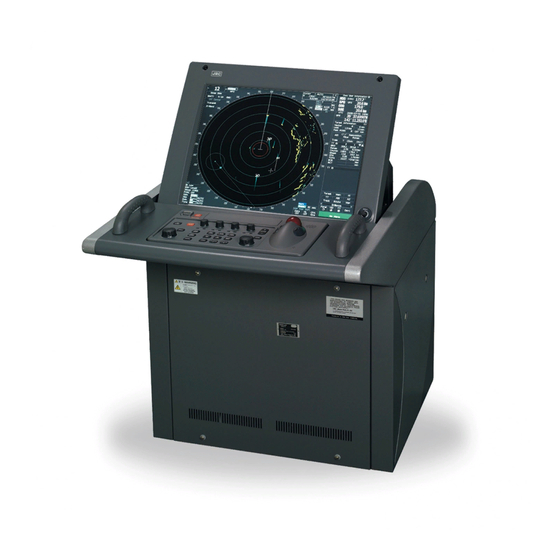
- Page 27 Monitor Unit Type NWZ-170 (Desktop type) Operation Unit Type NCE-5163 (Desktop type) Radar Process Unit Type NDC-1399-9 (Desktop type) DISPLAY UNIT TYPE NCD-4990T (DESKTOP TYPE)
-
Page 28: Glossary
GLOSSARY This section describes the main terms used for this equipment and general related maritime terms. Acquisition/Activation zone A zone set up by the operator in which the system should automatically acquire radar targets and activate reported AIS targets when entering the zone. Activated target A target representing the automatic or manual activation of a sleeping target for the display of additional information. - Page 29 CPA/TCPA The distance to the Closest Point of Approach/Time to the Closest Point of Approach. Limits are set by the operator and are related to own ship. Course Through Water The direction of the ship's movement through the water DRIFT The current velocity for manual correction or the current speed on the horizontal axis of the 2-axis log is displayed.
- Page 30 Lost AIS target A target symbol representing the last valid position of an AIS target before the reception of its data was lost, or its last dead-reckoned position. Lost tracked One for which target information is no longer available due to poor, lost or obscured signals.
- Page 31 Relative Motion A display on which the position of own ship remains fixed, and all targets move relative to own ship. RM(R) Relative Motion. Relative Trails. RM(T) Relative Motion. True Trails. Rate Of Turn Change of heading per time unit. Route A set of waypoints.
- Page 32 Trial manoeuvre A graphical simulation facility used to assist the operator to perform a proposed maneuver for navigation and collision avoidance purposes. True course The direction of motion relative to ground or to sea, of a target expressed as an angular displacement from north True speed The speed of a target relative to ground, or to sea True vector...
-
Page 33: Table Of Contents
Index ◆◆◆ PRECAUTIONS BEFORE OPERATION ◆◆◆ ..........i ◆◆◆ FIRST-AID TREATMENTS ◆◆◆ ..............ii PREFACE ........................v The Mounting Point of the Warning Label ..............xv EQUIPMENT APPEARANCE ................... xx GLOSSARY ......................xxvi SECTION 1 GENERAL AND EQUIPMENT COMPOSITION FUNCTIONS ...................1-1 1.1.1 Function of This System ..............1-1 FEATURES .....................1-2... - Page 34 3.2.7 Reset Alarm Buzzer [ALARM ACK] ..........3-12 3.2.8 ....3-13 To get the appropriate image that targets can be easily observed OPERATION PROCEDURES ..............3-14 3.3.1 Move Cross Cursor Mark by Trackball ........3-14 3.3.2 Operate Software Buttons ............3-15 3.3.3 Basic Menu Operation ..............3-16 3.3.4 ..3-17 Operation on Numeric Value, Latitude / Longitude and Character Input menu...
- Page 35 DISPLAY USER MAP ................3-47 3.6.1 Create User Map (Mark/Line) ............3-47 3.6.2 Set User Map Display (Mark Display Setting) ......3-50 3.6.3 Edit User Map (Edit User Map) .............3-52 3.6.4 Correct Position on User Map (Shift User Map) ......3-60 3.6.5 Save User Map ................3-61 3.6.6 Set and Display Geodetic System (Geodetic) ......3-65 USE ROUTE FUNCTION ..............3-67...
- Page 36 3.11 USING CARD ..................3-120 3.11.1 Operate File on the Card (File Manager) ........3-120 SECTION 4 MEASUREMENT OF RANGE AND BEARING USE OF NAVIGATION TOOLS ..............4-1 4.1.1 Using Cursor (Cursor) ..............4-2 4.1.2 Using Range Rings (Range Rings) ..........4-2 4.1.3 Using Electronic Bearing Line (EBL1/EBL2) ........4-3 4.1.4 Using Parallel Index Lines (PI Menu) ..........4-8 4.1.5...
- Page 37 AIS OPERATION ..................5-26 5.3.1 Restrictions ..................5-26 5.3.2 Setting AIS Display Function (AIS Function) ......5-26 5.3.3 Activate AIS Targets (Activate AIS) ..........5-27 5.3.4 Deactivate AIS Targets (Deactivate AIS) ........5-27 5.3.5 Displaying AIS Information [TGT DATA] ........5-28 5.3.6 Displaying Target ID No. (Target Number Display) ....5-31 5.3.7 Setting AIS Filter (AIS Filter Setting) ...........5-32 5.3.8...
- Page 38 SECTION 7 SETTINGS FOR SYSTEM OPERATION SETTINGS AT INSTALLATION .............7-1 7.1.1 How to Open the Serviceman Menu(Service Man Menu) ..7-1 7.1.2 GYRO I/F Setting ................7-2 7.1.3 Tuning (Tune Adjustment) .............7-5 7.1.4 Bearing Adjustment ................7-7 7.1.5 Range Adjustment ................7-7 7.1.6 Navigator Setting (Device) .............7-8 7.1.7 Setting of True Bearing Value ............7-9 7.1.8...
- Page 39 ROUTINE MAINTENANCE ..............8-1 MAINTENANCE ON EACH UNIT ............8-2 8.2.1 Scanner Unit NKE-1125/1129/1130/1139/2103/2254 ....8-2 8.2.2 Wave Guide Tube (JMA-9123-7XA/9XA) ........8-4 8.2.3 Coaxial Cable (JMA-9133-SA) ............8-4 8.2.4 Transmitter Receiver Unit (NTG-3225/3230) ........8-5 8.2.5 Display Unit (NCD-4990) ..............8-5 PERFORMANCE CHECK ..............8-6 8.3.1 Check Performance on Test Menu ..........8-6 REPLACEMENT OF MAJOR PARTS ..........8-12...
- Page 40 ABOUT THE CHINA ROHS ..............10-3 SECTION 11 SPECIFICATION 11.1 JMA-9133-SA TYPE RADAR ...............11-1 11.2 JMA-9132-SA TYPE RADAR ............... 11-2 11.3 JMA-9123-7XA/9XA TYPE RADAR ............11-3 11.4 JMA-9122-6XA/9XA TYPE RADAR ............11-4 11.5 JMA-9122-6XAH TYPE RADAR ............11-5 11.6 JMA-9110-6XA TYPE RADAR ............11-6 11.7 JMA-9110-6XAH TYPE RADAR ............11-7...
- Page 41 A.2.4 Change of Connection Pattern (with 3 or More Display Units) .. A-7 A.2.5 Operating Connection Pattern Files (File Operations) ....A-8 A.2.6 Names of Display Units and Scanner Units ......... A-9 REFERENCE ..................A-10 A.3.1 Preheat Time after Change of Connection Pattern ....A-10 A.3.2 Notes on Changing Connection Pattern ........
- Page 42 JMA-9110-6XA/JMA-9110-6XAH (desktop) ......... B-34 B.7.3 JMA-9122-6XAH ................B-35 B.7.4 JMA-9122-6XAH (desktop) ............B-36 B.7.5 JMA-9122-6XA/9XA ..............B-37 B.7.6 JMA-9123-7XA/9XA ..............B-38 B.7.7 JMA-9132-SA ................B-39 B.7.8 JMA-9133-SA ................B-40 B.7.9 NCD-4990T ..................B-41 GYRO I/F ..................... B-42 Inter Switch Unit ................. B-44 B.9.1...
- Page 43 GENERAL AND EQUIPMENT COMPOSITION NAMES AND FUNCTIONS OF CONTROL PANEL KEYS AND FUNCTIONS OF SOFTWARE BUTTONS BASIC OPERATION MEASUREMENT OF RANGE AND BEARING OPERATION OF TARGET TRACKING AND AIS TRUE AND FALSE ECHOES ON DISPLAY SETTINGS FOR SYSTEM OPERATION COUNTERMEASURES FOR TROUBLE AND ADJUSTMENT TROUBLE SHOOTING AND AFTER-SALES SERVICE...
-
Page 45: General And Equipment Composition
SECTION 1 GENERAL AND EQUIPMENT COMPOSITION GENERAL AND EQUIPMENT COMPOSITION FUNCTIONS ...................1-1 1.1.1 Function of This System ..............1-1 FEATURES .....................1-2 CONFIGURATION ..................1-4 EXTERIOR DRAWINGS .................1-6 GENERAL SYSTEM DIAGRAMS ............1-26... -
Page 47: Functions
> > JMA-9100 Instruction Manual 1.GENERAL AND EQUIPMENT COMPOSITION 1.1 FUNCTIONS FUNCTIONS This equipment is a high-performance radar equipment consisting of a scanner unit, a transmitter-receiver unit and a high resolution color LCD display unit. This equipment complies with the performance standard of IMO. 1.1.1 Function of This System The JMA-9100 series is a color radar system designed to comply with the... -
Page 48: Features
JMA-9100 Instruction Manual > 1.GENERAL AND EQUIPMENT COMPOSITION > 1.2 FEATURES FEATURES Realization of Large, Easy-to-see Screen with High Resolution The 23.1-inch color LCD with high resolution of 1600x1200 pixels can display radar images of 320 mm or more in diameter. Even short-range targets can also be displayed as high-resolution images. - Page 49 JMA-9100 Instruction Manual > 1.GENERAL AND EQUIPMENT COMPOSITION > 1.2 FEATURES Improved Day/Night Mode Five types of background colors are available in Day/Dusk/Night mode (total 5 background colors). Each background color can be reproduced to be suited for the user's operating environment by simple key operation. The radar echoes and a variety of graphics can also be represented in different colors, ensuring easy-to- see displays.
-
Page 50: Configuration
Output Power rotation JMA-9133-SA 12ft Slotted Antenna 30kW 24rpm CAT 1 JMA-9132-SA 12ft Slotted Antenna 30kW 24rpm CAT 1 JMA-9123-7XA 7ft Slotted Antenna 25kW 24rpm CAT 1 JMA-9123-9XA 9ft Slotted Antenna 25kW 24rpm CAT 1 JMA-9122-6XA 6ft Slotted Antenna 25kW... - Page 51 20MT H-7AWRD0003 JMA-9123-7XA/9XA FR-9 30MT H-7AWRD0004 In JMA-9133, the following type name of JRC is used for the RF coaxial cable between the scanner unit and the transmitter receiver unit. Type of Radar RF COAX cable Length(m) Type name of JRC...
-
Page 52: Exterior Drawings
JMA-9100 Instruction Manual > 1.GENERAL AND EQUIPMENT COMPOSITION > 1.4 EXTERIOR DRAWINGS EXTERIOR DRAWINGS Fig 1-1: Outline Drawing of Scanner Unit, Type NKE-1139 Fig 1-2: Outline Drawing of Scanner Unit, Type NKE-1130 Fig 1-3: Outline Drawing of Scanner Unit, Type NKE-1129-7 Fig 1-4: Outline Drawing of Scanner Unit, Type NKE-1129-9 Fig 1-5: Outline Drawing of Scanner Unit, Type NKE-1125-6 Fig 1-6: Outline Drawing of Scanner Unit, Type NKE-1125-9... - Page 53 JMA-9100 Instruction Manual > 1.GENERAL AND EQUIPMENT COMPOSITION > 1.4 EXTERIOR DRAWINGS Fig 1-1: Outline Drawing of Scanner Unit, Type NKE-1139 1- 7...
- Page 54 JMA-9100 Instruction Manual > 1.GENERAL AND EQUIPMENT COMPOSITION > 1.4 EXTERIOR DRAWINGS Fig 1-2: Outline Drawing of Scanner Unit, Type NKE-1130 1- 8...
- Page 55 JMA-9100 Instruction Manual > 1.GENERAL AND EQUIPMENT COMPOSITION > 1.4 EXTERIOR DRAWINGS Fig 1-3: Outline Drawing of Scanner Unit, Type NKE-1129-7 1- 9...
- Page 56 JMA-9100 Instruction Manual > 1.GENERAL AND EQUIPMENT COMPOSITION > 1.4 EXTERIOR DRAWINGS Fig 1-4: Outline Drawing of Scanner Unit, Type NKE-1129-9 1- 10...
- Page 57 JMA-9100 Instruction Manual > 1.GENERAL AND EQUIPMENT COMPOSITION > 1.4 EXTERIOR DRAWINGS Fig 1-5: Outline Drawing of Scanner Unit, Type NKE-1125-6 1- 11...
- Page 58 JMA-9100 Instruction Manual > 1.GENERAL AND EQUIPMENT COMPOSITION > 1.4 EXTERIOR DRAWINGS Fig 1-6: Outline Drawing of Scanner Unit, Type NKE-1125-9 1- 12...
- Page 59 JMA-9100 Instruction Manual > 1.GENERAL AND EQUIPMENT COMPOSITION > 1.4 EXTERIOR DRAWINGS Fig 1-7: Outline Drawing of Scanner Unit, Type NKE-2254-6HS 1- 13...
- Page 60 JMA-9100 Instruction Manual > 1.GENERAL AND EQUIPMENT COMPOSITION > 1.4 EXTERIOR DRAWINGS Fig 1-8: Outline Drawing of Scanner Unit, Type NKE-2103-6 1- 14...
- Page 61 JMA-9100 Instruction Manual > 1.GENERAL AND EQUIPMENT COMPOSITION > 1.4 EXTERIOR DRAWINGS Fig 1-9: Outline Drawing of Scanner Unit, Type NKE-2103-6HS 1- 15...
- Page 62 JMA-9100 Instruction Manual > 1.GENERAL AND EQUIPMENT COMPOSITION > 1.4 EXTERIOR DRAWINGS Fig 1-10: Outline Drawing of Transmitter Receiver Unit, Type NTG-3230 1- 16...
- Page 63 JMA-9100 Instruction Manual > 1.GENERAL AND EQUIPMENT COMPOSITION > 1.4 EXTERIOR DRAWINGS Fig 1-11: Outline Drawing of Transmitter Receiver Unit, Type NTG-3225 1- 17...
- Page 64 JMA-9100 Instruction Manual > 1.GENERAL AND EQUIPMENT COMPOSITION > 1.4 EXTERIOR DRAWINGS Fig 1-12: Outline Drawing of Display Unit, Type NCD-4990 1- 18...
- Page 65 JMA-9100 Instruction Manual > 1.GENERAL AND EQUIPMENT COMPOSITION > 1.4 EXTERIOR DRAWINGS Fig 1-13: Outline Drawing of Monitor Unit, Type NWZ-170 (Desktop type option) 1- 19...
- Page 66 JMA-9100 Instruction Manual > 1.GENERAL AND EQUIPMENT COMPOSITION > 1.4 EXTERIOR DRAWINGS Fig 1-14: NDOutline Drawing of Radar Process Unit, Type NDC-1399-9 (Desktop type option) 1- 20...
- Page 67 JMA-9100 Instruction Manual > 1.GENERAL AND EQUIPMENT COMPOSITION > 1.4 EXTERIOR DRAWINGS Fig 1-15: Outline Drawing of Operation Unit, Type NCE-5163 (Desktop type option) 1- 21...
- Page 68 JMA-9100 Instruction Manual > 1.GENERAL AND EQUIPMENT COMPOSITION > 1.4 EXTERIOR DRAWINGS Fig 1-16: Outline Drawing of AC/DC Converter Unit, Type NBA-5135 (Desktop type option) 1- 22...
- Page 69 JMA-9100 Instruction Manual > 1.GENERAL AND EQUIPMENT COMPOSITION > 1.4 EXTERIOR DRAWINGS Fig 1-17: Outline Drawing of Interswitch Unit, Type NQE-3141-4A (Option) 1- 23...
- Page 70 JMA-9100 Instruction Manual > 1.GENERAL AND EQUIPMENT COMPOSITION > 1.4 EXTERIOR DRAWINGS Fig 1-18: Outline Drawing of Interswitch Unit, Type NQE-3141-8A (Option) 1- 24...
- Page 71 JMA-9100 Instruction Manual > 1.GENERAL AND EQUIPMENT COMPOSITION > 1.4 EXTERIOR DRAWINGS Fig 1-19: Outline Drawing of Power Control Unit, Type NQE-3167 (Option) 1- 25...
-
Page 72: General System Diagrams
JMA-9100 Instruction Manual > 1.GENERAL AND EQUIPMENT COMPOSITION > 1.5 GENERAL SYSTEM DIAGRAMS GENERAL SYSTEM DIAGRAMS Fig 1-21: General System Diagram of Radar, Type JMA-9132-SA Fig 1-22: General System Diagram of Radar, Type JMA-9123-7XA Fig 1-23: General System Diagram of Radar, Type JMA-9123-9XA Fig 1-24: General System Diagram of Radar, Type JMA-9122-6XA... - Page 73 JMA-9100 Instruction Manual > 1.GENERAL AND EQUIPMENT COMPOSITION > 1.5 GENERAL SYSTEM DIAGRAMS NKE-1139 SCANNER UNIT NJU-84 PERFORMANCE UNIT CIRCUIT BREAKER (SHIP YARD SUPPLY) (5A) AC100V,60Hz 1φ,200 W ( W I T H P M U N I T) 0 . 6 /1 k V - D P Y C Y S- 1 .5 C O A X I A L C A B L E NBL-175 H F - 2 0 D ( J R C S U P P L Y)
- Page 74 JMA-9100 Instruction Manual > 1.GENERAL AND EQUIPMENT COMPOSITION > 1.5 GENERAL SYSTEM DIAGRAMS NKE-1130 SCANNER UNIT NJU-84 PERFORMANCE UNIT CIRCUIT BREAKER (SHIP YARD SUPPLY) (5A) AC100V,60Hz 1φ,200 W ( W I T H P M U N I T) 0. 6 /1 k V - D P Y C Y S- 1 .5 NBL-175 SHIP’S MAIN for HEATER...
- Page 75 250 V - T T YCS- 4 Fig 1-22: General System Diagram of Radar, Type JMA-9123-7XA Eliminating the interference on frequencies used for marine communications and navigation due to operation of the radar. All cables of the radar are to be run away from the cables of radio equipment.(Ex.
- Page 76 JMA-9100 Instruction Manual > 1.GENERAL AND EQUIPMENT COMPOSITION > 1.5 GENERAL SYSTEM DIAGRAMS NKE-1129-9 SCANNER UNIT NJU-85 PERFORMANCE UNIT CIRCUIT BREAKER (SHIP YARD SUPPLY) (5A) AC100V,60Hz 1φ,200 W ( W I T H P M U N I T) 0. 6 / 1 k V - D P Y C Y S- 1 .5 F L E X I B L E W A V E G U I D E NBL-175 F R - 9 ( J R C S U P P L Y)
- Page 77 JMA-9100 Instruction Manual > 1.GENERAL AND EQUIPMENT COMPOSITION > 1.5 GENERAL SYSTEM DIAGRAMS NKE-1125-6 SCANNER UNIT NJU-85 PERFORMANCE UNIT CIRCUIT BREAKER (SHIP YARD SUPPLY) (5A) AC100V,60Hz 1φ,200 W ( W I T H P M U N I T) 0 .6 /1 k V - D P Y C Y S- 1 .5 NBL-175 SHIP’S MAIN for HEATER...
- Page 78 JMA-9100 Instruction Manual > 1.GENERAL AND EQUIPMENT COMPOSITION > 1.5 GENERAL SYSTEM DIAGRAMS NKE-1125-9 SCANNER UNIT NJU-85 PERFORMANCE UNIT CIRCUIT BREAKER (SHIP YARD SUPPLY) (5A) AC100V,60Hz 1φ,200 W ( W I T H P M U N I T) 0. 6 /1 k V - D P Y C Y S- 1 .5 NBL-175 SHIP’S MAIN for HEATER...
- Page 79 JMA-9100 Instruction Manual > 1.GENERAL AND EQUIPMENT COMPOSITION > 1.5 GENERAL SYSTEM DIAGRAMS NKE-2254-6HS SCANNER UNIT NJU-85 PERFORMANCE UNIT CIRCUIT BREAKER (SHIP YARD SUPPLY) (5A) AC100V,60Hz 1φ,200 W ( W I T H P M U N I T) 0 .6 /1 k V - D P Y C Y S- 1 .5 NBL-175 SHIP’S MAIN for HEATER...
- Page 80 JMA-9100 Instruction Manual > 1.GENERAL AND EQUIPMENT COMPOSITION > 1.5 GENERAL SYSTEM DIAGRAMS NKE-2103-6 SCANNER UNIT NJU-85 PERFORMANCE UNIT 1 9 C O R E S C O M P O S I T E C A B L E C F Q - 6 9 1 2- * * M A X 1 4 .
- Page 81 JMA-9100 Instruction Manual > 1.GENERAL AND EQUIPMENT COMPOSITION > 1.5 GENERAL SYSTEM DIAGRAMS NKE-2103-6HS SCANNER UNIT NJU-85 PERFORMANCE UNIT 1 9 C O R E S C O M P O S I T E C A B L E C F Q - 6 9 1 2- * * M A X 1 4 .
- Page 82 JMA-9100 Instruction Manual > 1.GENERAL AND EQUIPMENT COMPOSITION > 1.5 GENERAL SYSTEM DIAGRAMS 1- 36...
- Page 83 SECTION 2 NAMES AND FUNCTIONS OF CONTROL PANEL KEYS AND FUNCTIONS OF SOFTWARE BUTTONS NAMES AND FUNCTIONS OF CONTROL PANEL KEYS AND FUNCTIONS OF SOFTWARE BUTTONS NAMES OF DISPLAY ................2-1 NAMES AND FUNCTIONS OF CONTROL PANEL KEYS ....2-11 FUNCTIONS OF SOFTWARE BUTTONS ...........2-16...
-
Page 85: Names Of Display
> > JMA-9100 Instruction Manual 2.CONTROL PANEL KEYS and SOFTWARE BUTTONS 2.1 NAMES OF DISPLAY NAMES OF DISPLAY Example of screen display In this example, the screen is divided into a number of areas and the names in each area are indicated. Upper left Upper right of the display... - Page 86 > > JMA-9100 Instruction Manual 2.CONTROL PANEL KEYS and SOFTWARE BUTTONS 2.1 NAMES OF DISPLAY Automatic acquisition / Association target Own ship's symbol activation zone Ship's heading marker Past position Ship's heading line AIS target number Cursor mark AIS target symbol Tracked target vector Tracked target...
- Page 87 > > JMA-9100 Instruction Manual 2.CONTROL PANEL KEYS and SOFTWARE BUTTONS 2.1 NAMES OF DISPLAY Upper left of the display Range scale Tuning indication Range rings display On / Off Range rings interval Transmission pulse length Motion mode true / relative Radar trail true / relative Stability mode Off center...
- Page 88 > > JMA-9100 Instruction Manual 2.CONTROL PANEL KEYS and SOFTWARE BUTTONS 2.1 NAMES OF DISPLAY Upper right of the display Cursor bearing Cursor bearing Cursor mode numeric value indication Cursor latitude true / relative Cursor range Cursor longitude EBL1 numeric value indication EBL1 true / relative starting point mode...
- Page 89 > > JMA-9100 Instruction Manual 2.CONTROL PANEL KEYS and SOFTWARE BUTTONS 2.1 NAMES OF DISPLAY Target tracking (TT) / AIS information Target tracking (TT) / Target vector true / relative Target vector length EPA / AIS Past position display TCPA limit interval CPA limit Past position display...
- Page 90 > > JMA-9100 Instruction Manual 2.CONTROL PANEL KEYS and SOFTWARE BUTTONS 2.1 NAMES OF DISPLAY Numeric information: Tracked target information Tracked target number Bearing True course Range True speed TCPA No information is displayed if digital information value is not displayed Numeric information: Enhancement of cursor position numeric value indication Cursor bearing numeric Cursor bearing...
- Page 91 > > JMA-9100 Instruction Manual 2.CONTROL PANEL KEYS and SOFTWARE BUTTONS 2.1 NAMES OF DISPLAY Numeric information: Enhancement of EBL / VRM numeric value display EBL bearing EBL bearing numeric value indication true / relative VRM range Numeric information: Navigation information Depth Current direction Water temperature...
- Page 92 > > JMA-9100 Instruction Manual 2.CONTROL PANEL KEYS and SOFTWARE BUTTONS 2.1 NAMES OF DISPLAY Graph information: Water temperature indication Water temperature Water temperature range Water temperature graph Time range Graph information: Wind direction / speed Wind direction / speed true / relative Wind direction Wind speed...
- Page 93 > > JMA-9100 Instruction Manual 2.CONTROL PANEL KEYS and SOFTWARE BUTTONS 2.1 NAMES OF DISPLAY Numeric information: Marker Marker bearing Marker latitude Marker range Marker longitude Arrival time Menu Main menu Digital information Parallel index line menu Automatic acquisition / Target Tracking (TT) menu activation zone (AZ) menu Own Track menu...
- Page 94 > > JMA-9100 Instruction Manual 2.CONTROL PANEL KEYS and SOFTWARE BUTTONS 2.1 NAMES OF DISPLAY Alarm Alarm indication (The system alarm indicated in red . Other information indicated in blue or yellow.) 2- 10...
-
Page 95: Names And Functions Of Control Panel Keys
> > JMA-9100 Instruction Manual 2.CONTROL PANEL KEYS and SOFTWARE BUTTONS 2.2 NAMES AND FUNCTIONS OF CONTROL PANEL KEYS NAMES AND FUNCTIONS OF CONTROL PANEL KEYS The name of each button is described from the following page. See below. 2- 11... - Page 96 > > JMA-9100 Instruction Manual 2.CONTROL PANEL KEYS and SOFTWARE BUTTONS 2.2 NAMES AND FUNCTIONS OF CONTROL PANEL KEYS [POWER] (Power supply) switch The lamp is lit and the equipment is activated. If this switch is pressed while the equipment is running, the power of the equipment is shut down.
- Page 97 > > JMA-9100 Instruction Manual 2.CONTROL PANEL KEYS and SOFTWARE BUTTONS 2.2 NAMES AND FUNCTIONS OF CONTROL PANEL KEYS [GAIN] (Gain/pulse length) dial This function adjusts the reception sensitivity of the radar. To increase the sensitivity, turn the dial clockwise. The transmission pulse width can be switched by pressing the dial.
- Page 98 > > JMA-9100 Instruction Manual 2.CONTROL PANEL KEYS and SOFTWARE BUTTONS 2.2 NAMES AND FUNCTIONS OF CONTROL PANEL KEYS [VRM] (Variable Range Marker) dial This function changes the range of the VRM that is selected by VRM1/2. By pressing the dial, the parallel line cursor function can be switched to Operation → Fixed →...
- Page 99 > > JMA-9100 Instruction Manual 2.CONTROL PANEL KEYS and SOFTWARE BUTTONS 2.2 NAMES AND FUNCTIONS OF CONTROL PANEL KEYS [DATA OFF] (DATA Off) key This function sets the graphics other than HL, range ring, EBL, and VRM to OFF temporarily while this key is pressed. →...
-
Page 100: Functions Of Software Buttons
> > JMA-9100 Instruction Manual 2.CONTROL PANEL KEYS and SOFTWARE BUTTONS 2.3 FUNCTIONS OF SOFTWARE BUTTONS FUNCTIONS OF SOFTWARE BUTTONS In this radar, the frequently used functions can be directly set from the screen without opening the menu by using the software buttons on the screen for quick handling. - Page 101 > > JMA-9100 Instruction Manual 2.CONTROL PANEL KEYS and SOFTWARE BUTTONS 2.3 FUNCTIONS OF SOFTWARE BUTTONS Upper left of the display ① Range scale switching ② Range rings display ⑦ Transmission pulse length On /Off switching ③ Motion mode true / relative switching ④...
- Page 102 > > JMA-9100 Instruction Manual 2.CONTROL PANEL KEYS and SOFTWARE BUTTONS 2.3 FUNCTIONS OF SOFTWARE BUTTONS Interswitch connection change This button is displayed when the interswitch is connected. This button indicates the connection status of the scanner unit that is connected to the indicator. If the button is clicked in the transmission standby state, the menu for changing the connection state between the scanner unit and the indicator is displayed.
- Page 103 > > JMA-9100 Instruction Manual 2.CONTROL PANEL KEYS and SOFTWARE BUTTONS 2.3 FUNCTIONS OF SOFTWARE BUTTONS Interference rejection (IR) mode switching The interference rejection mode is switched whenever this button is clicked. IR Off IR Low IR Meddle IR High IR Off ⇒...
- Page 104 > > JMA-9100 Instruction Manual 2.CONTROL PANEL KEYS and SOFTWARE BUTTONS 2.3 FUNCTIONS OF SOFTWARE BUTTONS Upper Right of the display ⑨ EBL1 numeric value indication ② Mark font / line pattern true / relative switching switching ① Cursor mode switching ③...
- Page 105 > > JMA-9100 Instruction Manual 2.CONTROL PANEL KEYS and SOFTWARE BUTTONS 2.3 FUNCTIONS OF SOFTWARE BUTTONS EBL1 / 2 and VRM1 / 2 adjustment These functions set the EBL1 , VRM1 , EBL2 , and VRM2 displays to On / Off and acquire the operation right.
- Page 106 > > JMA-9100 Instruction Manual 2.CONTROL PANEL KEYS and SOFTWARE BUTTONS 2.3 FUNCTIONS OF SOFTWARE BUTTONS Lower right of the display ③ Own ship's track interval switching ① Mark color switching ④ Own ship's track interval unit switching ② Own ship’s track color switching ⑤...
- Page 107 > > JMA-9100 Instruction Manual 2.CONTROL PANEL KEYS and SOFTWARE BUTTONS 2.3 FUNCTIONS OF SOFTWARE BUTTONS CPA ring display On / Off The CPA ring display is switched to On / Off whenever the button is clicked. When the target vector display mode is (true vector), the CPA ring cannot be set to Own ship's information ①...
- Page 108 > > JMA-9100 Instruction Manual 2.CONTROL PANEL KEYS and SOFTWARE BUTTONS 2.3 FUNCTIONS OF SOFTWARE BUTTONS Target tracking (TT) / AIS information ① Target vector display ② Target vector length setting ④ TCPA limit setting true / relative switching ⑥ Past position display ③...
- Page 109 > > JMA-9100 Instruction Manual 2.CONTROL PANEL KEYS and SOFTWARE BUTTONS 2.3 FUNCTIONS OF SOFTWARE BUTTONS Past position display interval switching The past position display interval is switched whenever the button is clicked. Past position display interval unit switching The past position display interval unit is switched whenever the button is clicked. ⇒...
- Page 110 > > JMA-9100 Instruction Manual 2.CONTROL PANEL KEYS and SOFTWARE BUTTONS 2.3 FUNCTIONS OF SOFTWARE BUTTONS Numeric information: AIS target information simple display ①:Detail / simple display switching ②:Unread message display Detail / simple display switching This function switches the display mode to detail / simple display when AIS target information is displayed.
- Page 111 > > JMA-9100 Instruction Manual 2.CONTROL PANEL KEYS and SOFTWARE BUTTONS 2.3 FUNCTIONS OF SOFTWARE BUTTONS Numeric information: Tracked target information ① Tracked target numeric value indication scroll Tracked target numeric value indication scroll This function scrolls the target numbers that are indicated in the tracked target information.
- Page 112 > > JMA-9100 Instruction Manual 2.CONTROL PANEL KEYS and SOFTWARE BUTTONS 2.3 FUNCTIONS OF SOFTWARE BUTTONS Graph information: Wind direction / speed ① Wind direction / speed numeric value indication true / relative switching Wind direction / speed numeric value indication true / relative switching The wind direction / speed numeric value indication is switched to (true) /...
- Page 113 > > JMA-9100 Instruction Manual 2.CONTROL PANEL KEYS and SOFTWARE BUTTONS 2.3 FUNCTIONS OF SOFTWARE BUTTONS AIS menu If the button is clicked, the AIS Menu is opened. Route menu If this button is clicked, the Route Menu is opened. Parallel index line menu If this button is clicked, the PI Menu is opened.
- Page 114 > > JMA-9100 Instruction Manual 2.CONTROL PANEL KEYS and SOFTWARE BUTTONS 2.3 FUNCTIONS OF SOFTWARE BUTTONS Display item switching The brilliance adjustment screen and display information setting screen interchange whenever this button is clicked. ⇔ Panel lighting brilliance switching This function enables the setting of the brilliance of the lighting of the control panel. The brilliance changes whenever this button is clicked.
- Page 115 > > JMA-9100 Instruction Manual 2.CONTROL PANEL KEYS and SOFTWARE BUTTONS 2.3 FUNCTIONS OF SOFTWARE BUTTONS Alarm ① Alarm acknowridgement ② Error log display Alarm acknowledgment If this button is clicked, the buzzer sound of the alarm that is currently issued is stopped and the alarm lamp stops blinking.
- Page 116 > > JMA-9100 Instruction Manual 2.CONTROL PANEL KEYS and SOFTWARE BUTTONS 2.3 FUNCTIONS OF SOFTWARE BUTTONS 2- 32...
-
Page 117: Basic Operation
SECTION 3 BASIC OPERATION BASIC OPERATION OPERATION FLOW ................3-1 3.1.1 Power ON and Start the System ............3-2 3.1.2 Observe and Adjust Video ..............3-4 3.1.3 Acquire and Measure Data .............3-4 3.1.4 Display and Measure with Reference to CCRP ......3-4 3.1.5 End the Operation and Stop the System ........3-5 OBSERVE AND ADJUST VIDEO ............3-6 3.2.1 Adjust Monitor Brilliance [BRILL] ..........3-6... - Page 118 3.3.2 Operate Software Buttons ............3-15 3.3.3 Basic Menu Operation ..............3-16 3.3.4 Operation on Numeric Value, Latitude / Longitude and Character Input menu ..................3-17 3.3.5 Overview of Menu Structure ............3-22 GENERAL RADAR OPERATION ............3-23 3.4.1 Interference Rejection (IR) ............3-23 3.4.2 Switch Transmitter Pulse Length [GAIN] ........3-24 3.4.3 Target Enhance (ENH) ..............3-25 3.4.4...
- Page 119 3.7.5 Method of Using Route ..............3-81 3.7.6 Detailed Route Settings ..............3-82 3.7.7 Clear Waypoint/Route Data (Clear WPT/Route Data) ....3-86 3.7.8 Operate Route Data File ..............3-87 APPLIED OPERATIONS ..............3-91 3.8.1 Set Radar Signal Processing (Process Setting) ......3-91 3.8.2 Set Radar Trails (RADAR Trails Setting) ........3-95 3.8.3 Set Scanner Unit (TXRX Setting) ..........3-97 3.8.4...
-
Page 121: Operation Flow
> > JMA-9100 Instruction Manual 3.BASIC OPERATION 3.1 OPERATION FLOW OPERATION FLOW Attention • Do not put anything on the operation panel. If you put anything hot on it, it may be deformed. • Do not give any impact to the operation panel, trackball, or controls. -
Page 122: Power On And Start The System
> > JMA-9100 Instruction Manual 3.BASIC OPERATION 3.1 OPERATION FLOW 3.1.1 Power ON and Start the System • A malfunction may occur if the power in the ship is instantaneously interrupted during operation of the radar. In this case, the power should be turned on again. - Page 123 > > JMA-9100 Instruction Manual 3.BASIC OPERATION 3.1 OPERATION FLOW Procedures Check that the ship’s mains are turned on. Press [POWER] key. The system is turned on, and the preheating time is displayed. Preheat is indicated at the upper left of the radar display. Wait until the preheating time is over.
-
Page 124: Observe And Adjust Video
> > JMA-9100 Instruction Manual 3.BASIC OPERATION 3.1 OPERATION FLOW 3.1.2 Observe and Adjust Video Procedures Press [RANGE+] key or [RANGE-] key to set the range to the scale required for target observation. [GAIN] [SEA] and [RAIN] to obtain the clearest targets. Refer to [GAIN] dial→... -
Page 125: End The Operation And Stop The System
> > JMA-9100 Instruction Manual 3.BASIC OPERATION 3.1 OPERATION FLOW 3.1.5 End the Operation and Stop the System Exit Press [TX/STBY] key. The radar will stop transmission and the antenna will stop rotating. Transmit Standby at the upper left of the radar display changes to Maintain the standby state if radar observation is restarted in a relatively short time.Only pressing the [TX/STBY] key starts observation. -
Page 126: Observe And Adjust Video
> > JMA-9100 Instruction Manual 3.BASIC OPERATION 3.2 OBSERVE AND ADJUST VIDEO OBSERVE AND ADJUST VIDEO 3.2.1 Adjust Monitor Brilliance [BRILL] Procedures Obtain the best-to-see display with optimum brilliance by turning the [BRILL] dial at the lower right of the monitor unit. Turning the [BRILL] dial clockwise increases the brilliance of the entire display. -
Page 127: Tune
> > JMA-9100 Instruction Manual 3.BASIC OPERATION 3.2 OBSERVE AND ADJUST VIDEO 3.2.3 Tune Normally, use the automatic tune mode. Use the manual tune mode only when best tuning is not possible in the automatic tune mode due to deterioration of magnetron. This radar system provides the automatic tune mode and the manual tune mode. -
Page 128: Adjust Gain [Gain]
> > JMA-9100 Instruction Manual 3.BASIC OPERATION 3.2 OBSERVE AND ADJUST VIDEO 3.2.4 Adjust Gain [GAIN] If the gain is too high, unnecessary signals including receiver noise and false images increase resulting in reduction of visibility of targets. On the contrary, if the gain is too low, targets including ships and dangerous objects may not be clearly indicated. -
Page 129: Suppress Sea Clutter [Sea]
> > JMA-9100 Instruction Manual 3.BASIC OPERATION 3.2 OBSERVE AND ADJUST VIDEO 3.2.5 Suppress Sea Clutter [SEA] When using the [AUTO SEA] function, never set the suppression level too high canceling out all image noises from the sea surface at close range. Detection of not only echoes from waves but also targets such as other ships or dangerous objects will become inhibited. - Page 130 > > JMA-9100 Instruction Manual 3.BASIC OPERATION 3.2 OBSERVE AND ADJUST VIDEO It is recommended to restore the setting to Current Level the factory default, if you lost the appropriate settings.The factory default level is shown on the bar chart as a green line. The factory defafult level is assigned by Factory Default every function mode.
-
Page 131: Suppress Rain/Snow Clutter [Rain]
> > JMA-9100 Instruction Manual 3.BASIC OPERATION 3.2 OBSERVE AND ADJUST VIDEO 3.2.6 Suppress Rain/Snow Clutter [RAIN] When using the [AUTO RAIN] function, never set the suppression level too high canceling out all image noises from the rain or snow at the close range. Detection of not only echoes from the rain or snow but also targets such as other ships or dangerous objects will become inhibited. -
Page 132: Reset Alarm Buzzer [Alarm Ack]
> > JMA-9100 Instruction Manual 3.BASIC OPERATION 3.2 OBSERVE AND ADJUST VIDEO 3.2.6.2 Using the automatic rain / snow clutter suppression mode The rain / snow clutter suppression in accordance with the intensity of rain / snow clutter is possible. Use this mode when the rain / snow clutter's intensity differs according to directional orientation. -
Page 133: To Get The Appropriate Image That Targets Can Be Easily Observed
> > JMA-9100 Instruction Manual 3.BASIC OPERATION 3.2 OBSERVE AND ADJUST VIDEO 3.2.8 To get the appropriate image that targets can be easily observed To get the appropriate image that targets can be easily observed which requires an understanding for RADAR signal processing features and an adjustment for the sea state. -
Page 134: Operation Procedures
> > JMA-9100 Instruction Manual 3.BASIC OPERATION 3.3 OPERATION PROCEDURES OPERATION PROCEDURES 3.3.1 Move Cross Cursor Mark by Trackball The cross cursor mark + is used for position designation and other purposes in various operating procedures. The cross cursor mark + moves in coupling with the trackball. -
Page 135: Operate Software Buttons
> > JMA-9100 Instruction Manual 3.BASIC OPERATION 3.3 OPERATION PROCEDURES 3.3.2 Operate Software Buttons Software buttons are provided on the radar display so as to easily switch functions without operating menu items. For software buttons that can be operated and their locations, see Section 2.3 "FUNCTIONS OF SOFTWARE BUTTONS". -
Page 136: Basic Menu Operation
> > JMA-9100 Instruction Manual 3.BASIC OPERATION 3.3 OPERATION PROCEDURES 3.3.3 Basic Menu Operation 3.3.3.1 To open the menu By left-clicking the Main button located at the lower right of the radar display, the main menu will open By left-clicking the buttons, , and , adjacent to Main... -
Page 137: Operation On Numeric Value, Latitude / Longitude And Character Input Menu
> > JMA-9100 Instruction Manual 3.BASIC OPERATION 3.3 OPERATION PROCEDURES 3.3.3.7 Menu Operation with the Trackball Item Selected item Press numeric keys corresponding to the desired item number to display the Present state selected item. Press numeric keys corresponding to the desired item number to Cursor select a set value. - Page 138 > > JMA-9100 Instruction Manual 3.BASIC OPERATION 3.3 OPERATION PROCEDURES 3.3.4.1 Numeric value input screen Entered value Numeric button - button + button Clear button Enter button 3.3.4.2 Directly entering a numeric value Procedures On the numeric value input screen, sequentially left-click the software number keys located on the radar screen, and enter a desired numeric value.
- Page 139 > > JMA-9100 Instruction Manual 3.BASIC OPERATION 3.3 OPERATION PROCEDURES 3.3.4.3 Increasing or decreasing a numeric value Procedures On the numeric value input screen, sequentially left-click the software button located on the radar screen, and + - enter a desired numeric value. For example, when adjusting 123.0°...
- Page 140 > > JMA-9100 Instruction Manual 3.BASIC OPERATION 3.3 OPERATION PROCEDURES 3.3.4.5 Entering latitude/longitude Procedures On the latitude/longitude input screen, sequentially click numeric buttons to enter latitude (XX°XX.XXX'). For example, to enter 12°34.567', sequentially click numeric buttons as follows. → → →...
- Page 141 A to Z, numbers from 0 to 9, or symbols (only comments for mark/line), and then left-click the ENT button to enter one character of the name to be inputted. For example, JRC for a name, click button as follows: → →...
-
Page 142: Overview Of Menu Structure
> > JMA-9100 Instruction Manual 3.BASIC OPERATION 3.3 OPERATION PROCEDURES 3.3.5 Overview of Menu Structure The menu structure of this radar system consists of eight frequently used function menus, one main menu, and one service man menu used for the installation settings. -
Page 143: General Radar Operation
> > JMA-9100 Instruction Manual 3.BASIC OPERATION 3.4 GENERAL RADAR OPERATION GENERAL RADAR OPERATION 3.4.1 Interference Rejection (IR) Interference by other radars is rejected. Attention • When viewing a radar beacon or SART signal, select IR Off (Interference Rejector OFF) because IR processing suppresses the video. -
Page 144: Switch Transmitter Pulse Length [Gain]
> > JMA-9100 Instruction Manual 3.BASIC OPERATION 3.4 GENERAL RADAR OPERATION 3.4.2 Switch Transmitter Pulse Length [GAIN] Procedures Press [GAIN] dial Values of the transmitter pulse width are switched. Effects of transmitter pulse width With selected: The transmitter pulse becomes shorter, and the range resolution improves. -
Page 145: Target Enhance (Enh)
> > JMA-9100 Instruction Manual 3.BASIC OPERATION 3.4 GENERAL RADAR OPERATION 3.4.3 Target Enhance (ENH) The dimension of video display is enlarged to enhance a target. Procedures Left-click the ENH button located at the lower left of the radar display. The target enlargement levels are switched. -
Page 146: Use Video Processing (Proc)
> > JMA-9100 Instruction Manual 3.BASIC OPERATION 3.4 GENERAL RADAR OPERATION 3.4.4 Use Video Processing (PROC) This function reduces unnecessary noise to highlight targets. Attention • When viewing a radar beacon, SART signal, or fast moving target on the radar display, select PROC Off (video process off). -
Page 147: Switch Azimuth Display Mode (Azi Mode)
> > JMA-9100 Instruction Manual 3.BASIC OPERATION 3.4 GENERAL RADAR OPERATION 3.4.5 Switch Azimuth Display Mode (AZI MODE) Select the bearing for the radar video to be displayed on the radar display. Procedures Left-click the AZI Mode button located at the lower left of the display. -
Page 148: Switch True/Relative Motion Display Mode (Tm/Rm)
> > JMA-9100 Instruction Manual 3.BASIC OPERATION 3.4 GENERAL RADAR OPERATION 3.4.6 Switch True/Relative Motion Display Mode (TM/RM) 3.4.6.1 Switching Relative Motion (RM) Mode to True Motion (TM) Mode Procedures Left-click the motion mode button located at the upper left of the radar display. -
Page 149: Move Own Ship's Display Position (Off Center)
> > JMA-9100 Instruction Manual 3.BASIC OPERATION 3.4 GENERAL RADAR OPERATION 3.4.7 Move Own Ship’s Display Position (Off Center) The own ship’s position can be moved from the display center to any position within 66% of the display radius. This function is convenient for observing a wide coverage in any direction. -
Page 150: Display Radar Trails (Trails)
> > JMA-9100 Instruction Manual 3.BASIC OPERATION 3.4 GENERAL RADAR OPERATION 3.4.8 Display Radar Trails (Trails) Other ship's movements and speeds can be monitored from the lengths and directions of their trails, serving for collision avoidance. The trail length varies according to setting. - Page 151 > > JMA-9100 Instruction Manual 3.BASIC OPERATION 3.4 GENERAL RADAR OPERATION 3.4.8.3 Trails Motion Mode There are two types of trails: relative motion trails and true motion trails. Relative motion The system plots the trails of a target at a position relative to trails: the own ship.
- Page 152 > > JMA-9100 Instruction Manual 3.BASIC OPERATION 3.4 GENERAL RADAR OPERATION 3.4.8.4 Changing Motion Mode of Trails (Trails Mode) Procedures Click the Trails Mode located at the upper right of the radar display. RADAR trails true/relative The trails motion modes are switched. ⇔...
-
Page 153: Zoom (X2)
> > JMA-9100 Instruction Manual 3.BASIC OPERATION 3.4 GENERAL RADAR OPERATION 3.4.9 Zoom (x2) This function doubles the size of radar video near a specified position. NOTE: If the range is 0.125 NM , this function is not available. Procedures Left-click the x2 button located at the lower left of the display. -
Page 154: Hide/Display Range Rings [Hl Off]
> > JMA-9100 Instruction Manual 3.BASIC OPERATION 3.4 GENERAL RADAR OPERATION 3.4.10 Hide/Display Range Rings [HL OFF] Procedures Press the [HL OFF] key. Alternatively, Left-click the button located at the lower right of the display. The ship's heading line (HL) is hidden while the [HL OFF] key is held down. The ship's heading line that indicates the course of own ship is always shown on the radar display. -
Page 155: Switch Day/Night Mode [Day/Night]
> > JMA-9100 Instruction Manual 3.BASIC OPERATION 3.4 GENERAL RADAR OPERATION 3.4.12 Switch Day/Night Mode [DAY/NIGHT] Several combinations of the display color and brilliance according to the ambient lighting conditions are provided. The display color setting is easily changed. Procedures Press the [DAY/NIGHT] key. -
Page 156: Set True Bearing
> > JMA-9100 Instruction Manual 3.BASIC OPERATION 3.4 GENERAL RADAR OPERATION 3.4.14 Set True Bearing When the GYRO I/F is used to enter a gyro signal, there is a rare case in which a true bearing value indicated by the master gyro does not match the true bearing value indicated by this radar system. -
Page 157: Magnet Compass Correction (Mag Compass Setting)
> > JMA-9100 Instruction Manual 3.BASIC OPERATION 3.4 GENERAL RADAR OPERATION NOTE: •If the single axis water log display can present the speed of the ship in other than the forward direction, the direction of movement should be indicated unambiguously. Therefore single axis water logs cannot detect the effect of leeway. - Page 158 > > JMA-9100 Instruction Manual 3.BASIC OPERATION 3.4 GENERAL RADAR OPERATION Set whether to make corrections or not. 1. Heading Correction ⇔ Input the correction value. + - Press the button to select south and north for latitude or the east and west for longitude.
-
Page 159: Use Own Ship's Track
> > JMA-9100 Instruction Manual 3.BASIC OPERATION 3.5 USE OWN SHIP'S TRACK USE OWN SHIP'S TRACK The own ship's track function saves and displays own ship's track. If navigation equipment is connected, this radar system records latitude/longitude data sent from the navigation equipment and displays own ship's track. NOTE: Even when own ship's track storage interval is turned , own ship's track can be displayed. -
Page 160: Set Display Color Of Own Ship's Track (Display Own Track Color)
> > JMA-9100 Instruction Manual 3.BASIC OPERATION 3.5 USE OWN SHIP'S TRACK 3.5.2 Set Display Color of Own Ship's Track (Display Own Track Color) Own ship's track can be saved in seven different colors. Own ship's track can be displayed or not displayed individually by color. Procedures Open the Display Own Track Setting menu by performing the menu operation... -
Page 161: Save Own Ship's Track (Own Track Memory)
> > JMA-9100 Instruction Manual 3.BASIC OPERATION 3.5 USE OWN SHIP'S TRACK 3.5.3 Save Own Ship's Track (Own Track Memory) To save own ship's track, storage at a specified time interval and at a specified range interval can be selected. The track storage interval can be selected from 10 preset time intervals and 8 preset range intervals. -
Page 162: Clear Own Ship's Track (Clear Own Track)
> > JMA-9100 Instruction Manual 3.BASIC OPERATION 3.5 USE OWN SHIP'S TRACK 3.5.5 Clear Own Ship's Track (Clear Own Track) This function cancels the storing of own ship's track. Procedures Open the Clear Own Track Color menu by performing the menu operation below. - Page 163 > > JMA-9100 Instruction Manual 3.BASIC OPERATION 3.5 USE OWN SHIP'S TRACK Procedures Left-click the button located at the lower right of the Track display. Track menu The Own Track Menu will appear. Left-click the item button of 3. Track Type The numeric value of the navigation data can be shown by the color of own ship's track.
-
Page 164: Use Water Depth Track (Water Depth Track)
> > JMA-9100 Instruction Manual 3.BASIC OPERATION 3.5 USE OWN SHIP'S TRACK 3.5.7 Use Water Depth Track (Water Depth Track) Set the corresponding conditions for the water depth value and the color of own ship's track by performing the operation below. Procedures Open the Water Depth Setting menu by performing the menu operation below. -
Page 165: Use Water Temperature Track (Water Temp Track)
> > JMA-9100 Instruction Manual 3.BASIC OPERATION 3.5 USE OWN SHIP'S TRACK 3.5.8 Use Water Temperature Track (Water TEMP Track) Set the corresponding conditions for the water temperature value and the color of own ship's track by performing the operation below. Procedures Open the Water TEMP. -
Page 166: Use Tidal Current Track (Current Vector Track)
> > JMA-9100 Instruction Manual 3.BASIC OPERATION 3.5 USE OWN SHIP'S TRACK 3.5.9 Use Tidal Current Track (Current Vector Track) Set the conditions for adding tidal current vectors to own ship's track by performing the operation below. Procedures Open the Current Setting menu by performing the menu operation below. -
Page 167: Display User Map
> > JMA-9100 Instruction Manual 3.BASIC OPERATION 3.6 DISPLAY USER MAP DISPLAY USER MAP Up to 20,000 items of NAV lines, coastlines, depth contours, and NAV marks can be created, displayed, loaded, and saved. (This function is available only when navigation equipment is connected to this radar system.) Marks that can be used : 29 types Lines that can be used : 3 types (solid, broken, and dashed-dotted line) - Page 168 > > JMA-9100 Instruction Manual 3.BASIC OPERATION 3.6 DISPLAY USER MAP Left-click the mark font button to select a font for the □ mark. The mark fonts are switched. Left-click the button located to the right of the mark font to select a color for the mark.
- Page 169 > > JMA-9100 Instruction Manual 3.BASIC OPERATION 3.6 DISPLAY USER MAP Move the cursor to a desired location on the radar display and left-click. A line is plotted between the previous point and the end point. Repeat this procedure so that sequential lines can be plotted.
-
Page 170: Set User Map Display (Mark Display Setting)
> > JMA-9100 Instruction Manual 3.BASIC OPERATION 3.6 DISPLAY USER MAP Left-click the button to input the latitude / 3. L/L longitude. For the input method on the latitude / longitude input screen, see Section 3.3.4.5 "Entering latitude/longitude" Left-click the button to input the comment. - Page 171 > > JMA-9100 Instruction Manual 3.BASIC OPERATION 3.6 DISPLAY USER MAP Specify whether to turn on or off the display for each type of mark and line. 1. All When is selected, the setting will reflect to all types of marks and lines. Off : All types are not displayed.
-
Page 172: Edit User Map (Edit User Map)
> > JMA-9100 Instruction Manual 3.BASIC OPERATION 3.6 DISPLAY USER MAP Specify the mark font size. Normal : The mark is displayed in normal size. Small : The mark is displayed in a size smaller than usual. 3.6.2.4 Setting the character size for comments Procedures Open the Comment Font Size menu by performing the menu operation below. - Page 173 > > JMA-9100 Instruction Manual 3.BASIC OPERATION 3.6 DISPLAY USER MAP Use the number buttons to enter a value of latitude (xx°xxx.xxx'). To make changes between north latitude and south latitude, use buttons. + - North latitude : Left-click the button.
- Page 174 > > JMA-9100 Instruction Manual 3.BASIC OPERATION 3.6 DISPLAY USER MAP The user map move mode is selected. Move Map is displayed in the cursor mode located at the upper right of the display. Put the cursor on a mark or line, and left-click. When a mark or line to be moved is selected, the cursor mark will appear.
- Page 175 > > JMA-9100 Instruction Manual 3.BASIC OPERATION 3.6 DISPLAY USER MAP 3.6.3.3 Deleting a mark or line (Delete) With regard to the created user map, a mark or line is deleted individually. Procedures Open the Edit User Map menu by performing the following menu operation.
- Page 176 > > JMA-9100 Instruction Manual 3.BASIC OPERATION 3.6 DISPLAY USER MAP 3.6.3.4 Inserting a vertex into a line (Insert/Move Vertex) With regard to the created user map, a vertex is inserted into a line. Procedures Open the Edit User Map menu by performing the following menu operation.
- Page 177 > > JMA-9100 Instruction Manual 3.BASIC OPERATION 3.6 DISPLAY USER MAP (Example) The side line into which a vertex is inserted Inserted vertex 3.6.3.5 Correcting the mark or vertex of a line (Insert/Move Vertex) With regard to the created user map, a mark or line is corrected. Procedures Open the Edit User Map menu by performing the following menu operation.
- Page 178 > > JMA-9100 Instruction Manual 3.BASIC OPERATION 3.6 DISPLAY USER MAP The cursor mode changes to the normal operation mode, terminating the user map insertion/correction mode. (Example) Original vertex New vertex 3.6.3.6 Deleting a mark or vertex from a line (Delete Vertex) With regard to the created user map, a vertex is deleted individually from a mark or line.
- Page 179 > > JMA-9100 Instruction Manual 3.BASIC OPERATION 3.6 DISPLAY USER MAP The cursor mode changes to the normal operation mode, terminating the user map delete mode. (Example) The vertex to be deleted 3.6.3.7 Batch clearing marks or lines (Clear) With regard to the created user map, marks or lines are batch cleared by type or by color. Procedures Open the Edit User Map menu by performing the following menu operation.
-
Page 180: Correct Position On User Map (Shift User Map)
> > JMA-9100 Instruction Manual 3.BASIC OPERATION 3.6 DISPLAY USER MAP Left-click the button. 1. Yes The selected mark will be deleted. NOTE: If data is not copied on the flash memory card (option), the data is not be reloaded. 3.6.4 Correct Position on User Map (Shift User Map) 3.6.4.1... -
Page 181: Save User Map
> > JMA-9100 Instruction Manual 3.BASIC OPERATION 3.6 DISPLAY USER MAP 3.6.4.2 Restoring the corrected user map to its original state (Shift Clear) Procedures Open the Mark Operations menu by performing the following menu operation. U.Map → 4. Shift Clear Only the most recently corrected data (for a single input) will be cleared, and the data will be displayed at its original position. - Page 182 > > JMA-9100 Instruction Manual 3.BASIC OPERATION 3.6 DISPLAY USER MAP Left-click the button. 3. Load The list of navigation data saved in the system will be displayed. Left-click the button for the file to be loaded. Confirmation Window will appear. Left-click the button.
- Page 183 > > JMA-9100 Instruction Manual 3.BASIC OPERATION 3.6 DISPLAY USER MAP Open the File Operations menu by performing the following menu operation. U.Map → 7. File Operation Left-click the item button of and select the 1. Select Card Slot card slot. Slot1 and Slot2 of the Select Card Slot items are switched.
- Page 184 > > JMA-9100 Instruction Manual 3.BASIC OPERATION 3.6 DISPLAY USER MAP Left-click the button. 6. Erase The Erace screen will appear. The list of navigation data saved in the card will be displayed. Click numeric buttons corresponding to the number for the file to be deleted.
-
Page 185: Set And Display Geodetic System (Geodetic)
> > JMA-9100 Instruction Manual 3.BASIC OPERATION 3.6 DISPLAY USER MAP 3.6.6 Set and Display Geodetic System (Geodetic) To create navigation information, set the geodetic system that is used with the connected navigation equipment. When navigation information is loaded, the geodetic system used when the navigation information was saved, is displayed. - Page 186 > > JMA-9100 Instruction Manual 3.BASIC OPERATION 3.6 DISPLAY USER MAP Table3-1: Geodetic System List # NAME 0 WGS-84 1 WGS-72 2 Japan 3 North American 1927(U.S) 4 North American 1927(Canada & Alaska) 5 European 1950 (Europe) 6 Australian geodetic 1966 (Australia) 7 Ordnance Survey of Great Britain (England) 8 NAD-83 9 - (No Use)
-
Page 187: Use Route Function
> > JMA-9100 Instruction Manual 3.BASIC OPERATION 3.7 USE ROUTE FUNCTION USE ROUTE FUNCTION In this radar system, a destination mark set by navigation equipment can be displayed, and a simple route can be created, displayed, loaded and saved. (To use this function, navigation equipment must be connected to this system) If radar video is poor visibility caused by route function, click the Map button to turn off the Map function. -
Page 188: Edit Route (Set Route Sequence)
> > JMA-9100 Instruction Manual 3.BASIC OPERATION 3.7 USE ROUTE FUNCTION 3.7.1.1 Displaying route created by the radar system (Internal) In this radar system, route created by the radar system are displayed as shown below. Planned Course 074T Route alarm line Waypoint 070T 12.5kn... - Page 189 > > JMA-9100 Instruction Manual 3.BASIC OPERATION 3.7 USE ROUTE FUNCTION Procedures Open the Set Route Sequence menu by performing the menu operation below. Route → 2. WPT/Route Setting → 3. Set Route Sequence Left-click the button. 7. New Monitor Route Confirmation Window will appear.
- Page 190 > > JMA-9100 Instruction Manual 3.BASIC OPERATION 3.7 USE ROUTE FUNCTION To add another Waypoint, repeat procedure 3. To finish adding a Waypoint, left-click twice at the last Waypoint. The Waypoint adding mode is cancelled. (Example) 062T 12.0kn Rubber band Last Waypoint 3.7.2.3 Correcting coordinates of a Waypoint (Correct Position)
- Page 191 > > JMA-9100 Instruction Manual 3.BASIC OPERATION 3.7 USE ROUTE FUNCTION Move the cursor to new coordinates, and left-click. The coordinates of the Waypoint are corrected, and then the Waypoint correcting mode is cancelled. (Example) 108T 108T 064T 064T 8.00kn 8.00kn 12.0kn 12.0kn...
- Page 192 > > JMA-9100 Instruction Manual 3.BASIC OPERATION 3.7 USE ROUTE FUNCTION On the radar display, put the cursor on the line extending between Waypoints that is to have its Planned Speed corrected. The section that is to have its Planned Speed corrected is specified, and the new Planned Speed is applied to the section.
- Page 193 > > JMA-9100 Instruction Manual 3.BASIC OPERATION 3.7 USE ROUTE FUNCTION On the radar display, put the cursor on a Waypoint to be deleted, and left-click. The specified Waypoint is deleted, and the previous and following Waypoints are then connected by a line. To delete another Waypoint, repeat procedure 3.
- Page 194 > > JMA-9100 Instruction Manual 3.BASIC OPERATION 3.7 USE ROUTE FUNCTION Left-click the button. 6. Insert The Waypoint inserting mode is selected. On the radar display, put the cursor on the section line into which a Waypoint is to be inserted, and left-click. The section is specified, the cursor becomes a cross cursor mark, and the cross cursor mark is connected to the previous and following Waypoints by a rubber band.
-
Page 195: Edit Route Make With Latitude And Longitude (Waypoint Input)
> > JMA-9100 Instruction Manual 3.BASIC OPERATION 3.7 USE ROUTE FUNCTION 3.7.3 Edit Route Make with Latitude and Longitude (Waypoint Input) In this radar system, it is possible to create and correct route by performing operation on the Waipoint Input menu. Waypoint Waypoint Number Waypoint Scroll... - Page 196 > > JMA-9100 Instruction Manual 3.BASIC OPERATION 3.7 USE ROUTE FUNCTION 3.7.3.2 Adding a Waypoint (Add) New Waypoint data is added to the route data saved in the radar system. Procedures Open the Waipoint Input menu. Left-click the button. The new latitude of waypoint is reversed. Enter a latitude / longitude and a planned speed.
- Page 197 > > JMA-9100 Instruction Manual 3.BASIC OPERATION 3.7 USE ROUTE FUNCTION 3.7.3.4 Correcting latitude / longitude of a Waypoint (LAT/LON) The latitude / longitude of a Waypoint in the route data saved in the radar system are corrected. Procedures Open the Waipoint Input menu. Left-click the Waypoint Scroll button.
- Page 198 > > JMA-9100 Instruction Manual 3.BASIC OPERATION 3.7 USE ROUTE FUNCTION 3.7.3.6 Deleting a Waypoint (DEL) The specified Waypoint in the route data saved in the radar system is deleted. Procedures Open the Waipoint Input menu. Left-click the Waypoint Scroll button. Left-click to show the desired waypoint.
-
Page 199: Use Route Monitoring Function (Waypoint/Route Alarm)
> > JMA-9100 Instruction Manual 3.BASIC OPERATION 3.7 USE ROUTE FUNCTION 3.7.4 Use Route Monitoring Function (Waypoint/Route Alarm) This radar system can monitor the movement of own ship with regard to its route and activate a variety of alarms. Destination alarm When own ship arrives at next Waypoint, an alarm will (Waypoint Alarm): be activated. - Page 200 > > JMA-9100 Instruction Manual 3.BASIC OPERATION 3.7 USE ROUTE FUNCTION Arrival Break Off : Set the operation mode. 0.00nm : Set the radius of the Waypoint alarm circle. If 0.00nm is set, alarm operation will be turned off. 3.7.4.2 Route Alarm The route alarm is activated when own ship deviates from the specified width of the route.
-
Page 201: Method Of Using Route
> > JMA-9100 Instruction Manual 3.BASIC OPERATION 3.7 USE ROUTE FUNCTION 3.7.5 Method of Using Route The method of using the route will be described. Displaying the route The internal route is displayed according to the procedures in (Route Alarm Color): Section 3.7.1 "Display Route/Destination Mark (Select Route)". -
Page 202: Detailed Route Settings
> > JMA-9100 Instruction Manual 3.BASIC OPERATION 3.7 USE ROUTE FUNCTION 3.7.5.2 Skipping/Back-skipping of the route (Waypoint Skip/ Waypoint Back Skip) Next Waypoint of the route can be changed by user manually. : Forward :Backward Skipping of route The Waypoint which is after the next Waypoint is set as the (Waypoint Skip): next Waypoint. - Page 203 > > JMA-9100 Instruction Manual 3.BASIC OPERATION 3.7 USE ROUTE FUNCTION Display character size :Specify the size of the numeric value and character displayed on the radar display. (SEL NUM/Comment Size) Waypoint bearing vector :Set the method to display line between next Waypoint and own ship.
- Page 204 > > JMA-9100 Instruction Manual 3.BASIC OPERATION 3.7 USE ROUTE FUNCTION Procedures Open the Next menu by performing the menu operation below. Route → 2. WPT/Route Setting → 9. Next Left-click the set value of the item, and 1. SEL NUM/Comment Size select an operation mode.
- Page 205 > > JMA-9100 Instruction Manual 3.BASIC OPERATION 3.7 USE ROUTE FUNCTION 3.7.6.4 Displaying bearing distance to the Waypoint (Status of Origin/DEST) Select a start point used to display bearing/distance in the Waypoint data display area. Procedures Open the Next menu by performing the menu operation below. Route → ...
-
Page 206: Clear Waypoint/Route Data (Clear Wpt/Route Data)
> > JMA-9100 Instruction Manual 3.BASIC OPERATION 3.7 USE ROUTE FUNCTION 3.7.6.6 Updating Waypoint data (Waypoint Switch Mode) Set how to update the Waypoint number when one Waypoint has been reached. Procedures Open the WPT/Route Operations menu by performing the menu operation below. -
Page 207: Operate Route Data File
> > JMA-9100 Instruction Manual 3.BASIC OPERATION 3.7 USE ROUTE FUNCTION 3.7.8 Operate Route Data File Route data saved in the radar system can be saved onto a flash memory card, and data can be loaded from a flash memory card into the radar system. With regard to this item, only route data can be saved and loaded. - Page 208 > > JMA-9100 Instruction Manual 3.BASIC OPERATION 3.7 USE ROUTE FUNCTION Procedures Insert a flash memory card into the card slot. Open the File Operations menu by performing the menu operation below. Route → 4. File Operation Left-click the 3. Save button.
- Page 209 > > JMA-9100 Instruction Manual 3.BASIC OPERATION 3.7 USE ROUTE FUNCTION Procedures Insert a flash memory card into the card slot. Open the File Operations menu by performing the menu operation below. Route → 4. File Operation Left-click the 2. Load button.
- Page 210 > > JMA-9100 Instruction Manual 3.BASIC OPERATION 3.7 USE ROUTE FUNCTION Left-click the button. 4. Erase Contents of the specified memory card (file list) will be displayed. Left-click the button for the desired file name. Confirmation Window will appear. Left-click the 1.
-
Page 211: Applied Operations
> > JMA-9100 Instruction Manual 3.BASIC OPERATION 3.8 APPLIED OPERATIONS APPLIED OPERATIONS 3.8.1 Set Radar Signal Processing (Process Setting) This function enables the setting of detail information about radar signal processing. Procedures Open the Process Setting menu by performing the menu operation below. - Page 212 > > JMA-9100 Instruction Manual 3.BASIC OPERATION 3.8 APPLIED OPERATIONS 3.8.1.2 Video Noise Rejection • This function rejects signals that assumed as noise and clutter in radar videos. • Select to display radar videos like analog signals. • Select to suppress noise and clutter. Level1 Level2 •...
- Page 213 > > JMA-9100 Instruction Manual 3.BASIC OPERATION 3.8 APPLIED OPERATIONS 3.8.1.4 Process Switch • This function sets a specific area and switches the video process mode between the inside and outside of the area. • In Section 3.8.1.5 "2nd Porcess Mode" 2nd Process Mode, set the second video process mode for the area outside the boundary.
- Page 214 > > JMA-9100 Instruction Manual 3.BASIC OPERATION 3.8 APPLIED OPERATIONS 3.8.1.7 Fast Target Detection • This function displays fast moving targets that are suppressed in scan- correlative process mode. • 3Scan CORREL 4Scan CORREL This function is enabled when , or 5Scan CORREL is selected as the video process mode.
-
Page 215: Set Radar Trails (Radar Trails Setting)
> > JMA-9100 Instruction Manual 3.BASIC OPERATION 3.8 APPLIED OPERATIONS 3.8.2 Set Radar Trails (RADAR Trails Setting) This function enables the setting of detail information about radar trails processing. Procedures Open the RADAR Trails Setting menu by performing the menu operation below. - Page 216 > > JMA-9100 Instruction Manual 3.BASIC OPERATION 3.8 APPLIED OPERATIONS 3.8.2.3 Trails Reduction • Make a setting for thinning radar trails. • The effect of thinning increases in order of → → Level1 Level2 Level3 • Radar videos do not become obscure because of the thinning of radar trails. : Disables the Trails Reduction function.
-
Page 217: Set Scanner Unit (Txrx Setting)
> > JMA-9100 Instruction Manual 3.BASIC OPERATION 3.8 APPLIED OPERATIONS 3.8.3 Set Scanner Unit (TXRX Setting) This function enables the setting of detail information about an antenna. Procedures Open the TXRX Setting menu by performing the menu operation below. Main → ... -
Page 218: Set Cursor (Cursor Setting)
> > JMA-9100 Instruction Manual 3.BASIC OPERATION 3.8 APPLIED OPERATIONS 3.8.3.4 Ice Class Standby Mode • In this mode, the antenna is rotated when transmission is in the standby state. • This mode is effective to prevent the antenna's rotating shaft from freezing. :The ice class standby mode is not used. -
Page 219: Set Radar Display (Display Setting)
> > JMA-9100 Instruction Manual 3.BASIC OPERATION 3.8 APPLIED OPERATIONS 3.8.4.2 Cursor Length • Set the length of the cross cursor mark on the radar display. Short Cuts the cross cursor mark in length. Long : Makes the cross cursor mark twice as long as when Short is selected. - Page 220 > > JMA-9100 Instruction Manual 3.BASIC OPERATION 3.8 APPLIED OPERATIONS 3.8.5.2 Day/Night • Specify the mode to be changed. • The following modes are available: Day1 : Day mode 1 : Used under bright lighting conditions. Day2 : Day mode 2 : Used under bright lighting conditions.
- Page 221 > > JMA-9100 Instruction Manual 3.BASIC OPERATION 3.8 APPLIED OPERATIONS Procedures Open the Brilliance Setting menu by performing the menu operation below. Main → 7. Sub Menu → 2. Brilliance Setting Display Brilliance Setting menu will appear. Setting brilliance of each element •...
-
Page 222: Adjust Sound Volume (Buzzer Volume)
> > JMA-9100 Instruction Manual 3.BASIC OPERATION 3.8 APPLIED OPERATIONS 3.8.5.5 Setting target symbol brilliance (TT) The brilliance of the target symbol on the radar display is adjusted. Procedures ○ Left-click the button located at the lower right of the radar display, and adjust the brilliance of the target symbol so as to get the best view of the video display. -
Page 223: Set User Option Keys [Option 1/2]
> > JMA-9100 Instruction Manual 3.BASIC OPERATION 3.8 APPLIED OPERATIONS 3.8.7 Set User Option Keys [OPTION 1/2] Users can freely make settings with [OPTION 1] key and [OPTION 2] key. By using the keys, users can open a frequently used menu by only single operation, or assign special functions, to the user key switches. - Page 224 > > JMA-9100 Instruction Manual 3.BASIC OPERATION 3.8 APPLIED OPERATIONS 3.8.7.2 Using Option Keys (Directly displaying a specified Menu Preset the that is to be displayed with the option key switch. Menu Procedures Perform the general menu open procedure to open the menu that is to be directly displayed with Option Key.
-
Page 225: Set Navigation Data Display (Multi Window Setting)
> > JMA-9100 Instruction Manual 3.BASIC OPERATION 3.8 APPLIED OPERATIONS 3.8.8 Set Navigation Data Display (Multi Window Setting) By performing the following operation, it is possible to display navigation data of the wind direction / velocity, water depth and the like, as a graph on the radar display. - Page 226 > > JMA-9100 Instruction Manual 3.BASIC OPERATION 3.8 APPLIED OPERATIONS • Navigation information of the water depth, water temperature, tidal current, wind direction/velocity, and destination is displayed with numeric values. • Left-click the button located at thelower righit of the display. The Target navigation data display function is switched between On and Off.
- Page 227 > > JMA-9100 Instruction Manual 3.BASIC OPERATION 3.8 APPLIED OPERATIONS 10min : Sets 10 minutes as the time range. : Sets 15 minutes as the time range. 15min 30min : Sets 30 minutes as the time range. 60min : Sets 60 minutes as the time range. 12hour : Sets 12 hours as the time range.
- Page 228 > > JMA-9100 Instruction Manual 3.BASIC OPERATION 3.8 APPLIED OPERATIONS 3.8.8.5 TEMP Graph Setting • The TEMP Graph Setting menu will appear. [1] TEMP Graph Display • Determine whether to display the graph of the water-temperature data that has been received on the radar display. •...
- Page 229 > > JMA-9100 Instruction Manual 3.BASIC OPERATION 3.8 APPLIED OPERATIONS 3.8.8.6 Course Bar Setting • The Course Bar Setting menu will appear. [1] Course Bar Display • Determine whether to display the bar graph for the course data that has been received on the radar display.
-
Page 230: Auto Backup
> > JMA-9100 Instruction Manual 3.BASIC OPERATION 3.8 APPLIED OPERATIONS 3.8.9 AUTO Backup Data can be automatically backed up when the power supply is turned on. Procedures Insert a flash memory card into the card slot. Flash memory card (option) is necessary. Open the Plot Setting menu by performing the following menu operation. - Page 231 > > JMA-9100 Instruction Manual 3.BASIC OPERATION 3.9 USE FUNCTION KEY [USER] USE FUNCTION KEY [USER] "Radar Function Setting" is provided for easily obtaining the best radar video by storing complex radar signal processing settings in the optimum status by use, and calling the setting in accordance with the conditions for using the function.
-
Page 232: Function Setting Menu Items
> > JMA-9100 Instruction Manual 3.BASIC OPERATION 3.9 USE FUNCTION KEY [USER] 3.9.1.3 Changing Function Setting (memory contents change) To change the memory contents of functions 1 to 4, use the function setting menu. For how to operate the function setting menu, see Section 3.9.3 "Overview of Function Operations (User Function Setting)". -
Page 233: Overview Of Function Operations (User Function Setting)
> > JMA-9100 Instruction Manual 3.BASIC OPERATION 3.9 USE FUNCTION KEY [USER] 3.9.3 Overview of Function Operations (User Function Setting) The following outlines the operation of each function selected from the function setting menu: Procedures Open the Process Setting menu by performing the menu operation below. - Page 234 > > JMA-9100 Instruction Manual 3.BASIC OPERATION 3.9 USE FUNCTION KEY [USER] page 1-[2] IR (Radar interference rejection) • Same function as IR Setting described in Section 3.4.1 "Interference Rejection (IR)". page 1-[3] Process (Video process) • Same function as PROCESS Setting described in Section 3.4.4 "Use Video Processing (PROC)"...
- Page 235 > > JMA-9100 Instruction Manual 3.BASIC OPERATION 3.9 USE FUNCTION KEY [USER] page 2-[1]~[7] PL (Pulse Length) • Sets the standard transmitter pulse length in each range. • When the range is called, the pulse range is used. page 3-[1]~[7] Video setting menu (Process Setting) •...
- Page 236 > > JMA-9100 Instruction Manual 3.BASIC OPERATION 3.9 USE FUNCTION KEY [USER] page 5-[3] Small Buoy Detection • Reduces the loss of signal processing during detection of small targets. :Activates the general signal processing mode. :Activates the small buoy detection mode that reduces the loss of signal processing.
-
Page 237: Overview Of Saved Function Setting Data
> > JMA-9100 Instruction Manual 3.BASIC OPERATION 3.9 USE FUNCTION KEY [USER] 3.9.4 Overview of saved Function Setting Data The overview of saved function setting data is as follows: Factory-set data: : Saved data that general operation cannot change Default data: : Standard data of each function mode that users can change Data that can be : Saved data that can be called by pressing the [USER] key... -
Page 238: 3.10 Use User Setting
> > JMA-9100 Instruction Manual 3.BASIC OPERATION 3.10 USE USER SETTING 3.10 USE USER SETTING The operation status of the radar is recorded. If the system is operated by more than one operator, the operators can register operation status as suitable for them and call the status. -
Page 239: Load Operating State (Load User Setting)
> > JMA-9100 Instruction Manual 3.BASIC OPERATION 3.10 USE USER SETTING 3.10.2 Load Operating State (Load User Setting) The operating state saved in the system can be loaded by performing the operation below. When the operating state is loaded, the previous operating state data is discarded. Therefore, if you do not want to discard the operating state data, save the operating state by performing the operation described in Section 3.10.1 "Save Operating State (Save User Setting)". -
Page 240: Using Card
> > JMA-9100 Instruction Manual 3.BASIC OPERATION 3.11 USING CARD 3.11 USING CARD This radar has two card slots. Inserting a flash memory card (option) into a card slot, you can save the following contents, saved in the processor, in the card or can load data from the card to the processor. - Page 241 > > JMA-9100 Instruction Manual 3.BASIC OPERATION 3.11 USING CARD The File Manager window will appear. Copy file from Device 1 selected device 1 to device 2 Device 2 format Device 2 Type of file selected displayed Device 1 Device 2 device type device type Device 1 format...
- Page 242 > > JMA-9100 Instruction Manual 3.BASIC OPERATION 3.11 USING CARD 3.11.1.1 Copy Internal Information to Card (Copy Internal -> Card) Procedures While the File Manager window is open, left-click the device 1 selection button. Selected items for Device1 will be displayed. Left-click the button among the selection items.
- Page 243 > > JMA-9100 Instruction Manual 3.BASIC OPERATION 3.11 USING CARD 3.11.1.2 Load Information from Card to Internal Portion (Copy Card -> Internal) Procedures While the File Manager window is open, left-click the device 1 selection button. Selected items for Device1 will be displayed. Left-click the button among the selection items.
- Page 244 > > JMA-9100 Instruction Manual 3.BASIC OPERATION 3.11 USING CARD 3.11.1.3 Copy Information (Copy) Procedures While the File Manager window is open, left-click the device 1 selection button. Selected items for Device1 will be displayed. Left-click the button corresponding to the device from which data is to be copied.
- Page 245 > > JMA-9100 Instruction Manual 3.BASIC OPERATION 3.11 USING CARD 3.11.1.4 Erase File (Erase) Procedures While the File Manager window is open, left-click the device 1 selection button. Selected items for Device1 will be displayed. Left-click button corresponding to the device in which data to be erased is saved.
- Page 246 > > JMA-9100 Instruction Manual 3.BASIC OPERATION 3.11 USING CARD 3.11.1.6 Showing data saved on the card (Show Card) Procedures While the File Manager window is open, left-click the device 1 selection button. Selected items for Device1 or Device2 will be displayed. Left-click button corresponding to the device in which data to be displayed is saved.
- Page 247 SECTION 4 MEASUREMENT OF RANGE AND BEARING MEASUREMENT OF RANGE AND BEARING USE OF NAVIGATION TOOLS ..............4-1 4.1.1 Using Cursor (Cursor) ..............4-2 4.1.2 Using Range Rings (Range Rings) ..........4-2 4.1.3 Using Electronic Bearing Line (EBL1/EBL2) ........4-3 4.1.4 Using Parallel Index Lines (PI Menu) ..........4-8 4.1.5 Operating EBL Maneuver Function (EBL Maneuver Setting) ..4-14 4.1.6...
-
Page 249: Measurement Of Range And Bearing
> > JMA-9100 Instruction Manual 4.MEASUREMENT OF RANGE AND BEARING 4.1 USE OF NAVIGATION TOOLS USE OF NAVIGATION TOOLS The system is equipped with the navigation tools below. Cursor: Specifies an arbitrary point, and measures the range and bearing from the own ship. Range Rings: Displays concentric circles with own ship's position as the center at specified intervals, and the rings are used as rough guides for range measurement. -
Page 250: Using Cursor (Cursor)
> > JMA-9100 Instruction Manual 4.MEASUREMENT OF RANGE AND BEARING 4.1 USE OF NAVIGATION TOOLS 4.1.1 Using Cursor (Cursor) Procedures Move the cursor onto the PPI display by moving the trackball. When the cursor is moved onto the PPI display, the arrow cursor turns into a cross cursor. 4.1.2 Using Range Rings (Range Rings) Procedures... -
Page 251: Using Electronic Bearing Line (Ebl1/Ebl2)
> > JMA-9100 Instruction Manual 4.MEASUREMENT OF RANGE AND BEARING 4.1 USE OF NAVIGATION TOOLS 4.1.3 Using Electronic Bearing Line (EBL1/EBL2) Electronic bearing lines (EBL) are indispensable to the measurement of bearings. Operators must be familiar with the operation of EBL beforehand. The system is equipped with two EBL. - Page 252 > > JMA-9100 Instruction Manual 4.MEASUREMENT OF RANGE AND BEARING 4.1 USE OF NAVIGATION TOOLS 4.1.3.1 Operating EBL (EBL) Procedures Press the [EBL1] or [EBL2] key. The EBL button (located at the upper right of the display) will be highlighted, and the selected EBL becomes operable.
- Page 253 > > JMA-9100 Instruction Manual 4.MEASUREMENT OF RANGE AND BEARING 4.1 USE OF NAVIGATION TOOLS [2] To return the EBL starting point to own ship's position Procedures Make EBL1 or EBL2 operable. Press the [EBL] dial to set for the EBL1 / EBL2 starting point mode switching located at the upper right of the display.
- Page 254 > > JMA-9100 Instruction Manual 4.MEASUREMENT OF RANGE AND BEARING 4.1 USE OF NAVIGATION TOOLS Procedures Open the EBL/Cursor Setting menu by performing the following menu operation. Main → 7. Sub Menu → 9. EBL/Cursor Setting Left-click at the item button 1.
- Page 255 > > JMA-9100 Instruction Manual 4.MEASUREMENT OF RANGE AND BEARING 4.1 USE OF NAVIGATION TOOLS EBL2 VRM2 EBL1 VRM1 VRM Operation The range value of the current on the PPI display is shown in the VRM1 VRM2 VRM1/2 range located at the upper right of the display. The currently operable VRM1 or VRM2 is highlighted in the VRM1 button located at the upper right of the...
-
Page 256: Using Parallel Index Lines (Pi Menu)
> > JMA-9100 Instruction Manual 4.MEASUREMENT OF RANGE AND BEARING 4.1 USE OF NAVIGATION TOOLS 4.1.4 Using Parallel Index Lines (PI Menu) Parallel index lines can be displayed. 4.1.4.1 Operating Parallel Index Lines (PI) Procedures Press the [VRM] dial. Parallel index lines and the PI Menu will appear. To change the bearing of parallel index lines, turn the [EBL] dial, to change the line interval, turn the [VRM] dial. - Page 257 > > JMA-9100 Instruction Manual 4.MEASUREMENT OF RANGE AND BEARING 4.1 USE OF NAVIGATION TOOLS ① ③ ② ④ EBL1 EBL2 VRM 1 VRM 2 ① ② ③ ④ During the operation of parallel index lines, pressing the [EBL1] or [EBL2] key disables operation for rotation directions.
- Page 258 > > JMA-9100 Instruction Manual 4.MEASUREMENT OF RANGE AND BEARING 4.1 USE OF NAVIGATION TOOLS [2] Operation Mode Sets an operation mode for parallel index lines. Individual Track Equiangular :All the parallel lines are operated at the same time. Individual :The bearing of each line is operated individually.
- Page 259 > > JMA-9100 Instruction Manual 4.MEASUREMENT OF RANGE AND BEARING 4.1 USE OF NAVIGATION TOOLS [3] Control Determines whether to operate all the lines at the same time. The setting items are determined by the setting of Section [2] "Operation Mode". a.
- Page 260 > > JMA-9100 Instruction Manual 4.MEASUREMENT OF RANGE AND BEARING 4.1 USE OF NAVIGATION TOOLS [6] Next Moves to the next page. [7] Range Scale Link Determines the operation of parallel index line intervals when the range is changed. :The intervals are fixed with the actual range (nm). The appearance of parallel index line intervals changes when the range is changed.
- Page 261 > > JMA-9100 Instruction Manual 4.MEASUREMENT OF RANGE AND BEARING 4.1 USE OF NAVIGATION TOOLS c. If is selected Track True : Displayed with true bearing (with North as reference). : Displayed with the heading line as reference. Line8 Index Line1 : Displayed with a specified line as reference.
-
Page 262: Operating Ebl Maneuver Function (Ebl Maneuver Setting)
> > JMA-9100 Instruction Manual 4.MEASUREMENT OF RANGE AND BEARING 4.1 USE OF NAVIGATION TOOLS 4.1.5 Operating EBL Maneuver Function (EBL Maneuver Setting) 4.1.5.1 Initial Setting (EBL Maneuver Setting) Procedures Open the EBL Maneuver Setting menu by performing the following menu operation. Main ... - Page 263 > > JMA-9100 Instruction Manual 4.MEASUREMENT OF RANGE AND BEARING 4.1 USE OF NAVIGATION TOOLS 4.1.5.2 Creation of Maneuver Curve (EBL Maneuver) Procedures Left-click the item button of 1. EBL Maneuver while the EBL Maneuver Setting menu is open. The EBL maneuver function will be set to on or off. A auxiliary line for maneuver curve creation, a maneuver curve, and a WOL will appear on the radar display.
-
Page 264: Operating Ebl, Vrm, And Pi With Cursor
> > JMA-9100 Instruction Manual 4.MEASUREMENT OF RANGE AND BEARING 4.1 USE OF NAVIGATION TOOLS 4.1.6 Operating EBL, VRM, and PI with Cursor When the cursor mode is set to (located at the upper right of the AUTO display), EBL, VRM, and PI can be operated simply by using the trackball. 4.1.6.1 Operating Electronic Bearing Line (EBL) Procedures... - Page 265 > > JMA-9100 Instruction Manual 4.MEASUREMENT OF RANGE AND BEARING 4.1 USE OF NAVIGATION TOOLS 4.1.6.3 Operating EBL and VRM Concurrently (EBL・VRM) Procedures Put the cursor on the intersection marker ( ○ or ● ), and left- click. EBL1 VRM1 EBL2 VRM2 When the cursor is moved to it,...
- Page 266 > > JMA-9100 Instruction Manual 4.MEASUREMENT OF RANGE AND BEARING 4.1 USE OF NAVIGATION TOOLS [2] To change parallel index line intervals Procedures Put the cursor on near the end of line, and left-click. When the cursor is moved there, it will turn into will be displayed at the upper right of the cursor.
-
Page 267: Measurement Of Range And Bearing
> > JMA-9100 Instruction Manual 4.MEASUREMENT OF RANGE AND BEARING 4.2 MEASUREMENT OF RANGE AND BEARING MEASUREMENT OF RANGE AND BEARING 4.2.1 Measurement with Cursor Position (Cursor) Procedures Make sure of the target echoes on the radar display. Move the cursor to the target. The bearing and range of the target will be shown in the Cursor bearing / range located at the upper right of the display. -
Page 268: Measurement With Electronic Bearing Line And Variable Range Marker [Ebl] [Vrm]
> > JMA-9100 Instruction Manual 4.MEASUREMENT OF RANGE AND BEARING 4.2 MEASUREMENT OF RANGE AND BEARING 4.2.2 Measurement with Electronic Bearing Line and Variable Range Marker [EBL] [VRM] Procedures Press the [EBL1] key. EBL1 numeric value indication EBL1 adjustment true / relative switching (located at the upper EBL1 right of the display) will be... -
Page 269: Measurement With Two Arbitrary Points
> > JMA-9100 Instruction Manual 4.MEASUREMENT OF RANGE AND BEARING 4.2 MEASUREMENT OF RANGE AND BEARING 4.2.3 Measurement with Two Arbitrary Points Procedures Press the [EBL2] key. EBL2 ( located at the upper right of the display) will be highlighted, and EBL2 will be shown on the PPI display. - Page 270 > > JMA-9100 Instruction Manual 4.MEASUREMENT OF RANGE AND BEARING 4.2 MEASUREMENT OF RANGE AND BEARING 4- 22...
- Page 271 SECTION 5 OPERATION OF TARGET TRACKING AND AIS OPERATION OF TARGET TRACKING AND AIS PREPARATION ..................5-1 5.1.1 Collision Avoidance ................5-2 5.1.2 Definitions of Symbols ..............5-5 5.1.3 Radar Display ..................5-8 5.1.4 Cursor Modes (Cursor) ..............5-10 5.1.5 Setting Collision Decision Criteria ..........5-12 5.1.6 Setting Vectors (Vector Time) ............5-13 5.1.7...
- Page 272 5.3.1 Restrictions ..................5-26 5.3.2 Setting AIS Display Function (AIS Function) ......5-26 5.3.3 Activate AIS Targets (Activate AIS) ..........5-27 5.3.4 Deactivate AIS Targets (Deactivate AIS) ........5-27 5.3.5 Displaying AIS Information [TGT DATA] ........5-28 5.3.6 Displaying Target ID No. (Target Number Display) ....5-31 5.3.7 Setting AIS Filter (AIS Filter Setting) ...........5-32 5.3.8...
- Page 273 > > JMA-9100 Instruction Manual 5.OPERATION OF TARGET TRACKING AND AIS 5.1 PREPARATION PREPARATION Attention • There are the following limitations on use of the target acquisition and target tracking functions. [I] Resolution between adjacent targets and swapping during automatic target tracking Depending on the particular distance and echo size, resolution between adjacent targets during automatic target tracking usually ranges somewhere between 0.03 to...
- Page 274 > > JMA-9100 Instruction Manual 5.OPERATION OF TARGET TRACKING AND AIS 5.1 PREPARATION If the mode is ground stabilization, SOG/COG used for own ship's information in target tracking. If the mode is sea stabilization, SPD (speed through the water) / HDG (heading) used for own ship's information in target tracking.
- Page 275 > > JMA-9100 Instruction Manual 5.OPERATION OF TARGET TRACKING AND AIS 5.1 PREPARATION 5.1.1.2 Marine Accidents and Collisions Among marine accidents, collision accidents have been highlighted as the tonnages and speeds of ships become higher along with the increase in traffic at sea.
- Page 276 > > JMA-9100 Instruction Manual 5.OPERATION OF TARGET TRACKING AND AIS 5.1 PREPARATION 5.1.1.4 Relative Vector and True Vector From two points of view, collision prediction and avoidance, it is necessary to obtain the relative vector of other ship for prediction and the true vector of other ship for collision avoidance in order to grasp other ship’s aspect.
- Page 277 > > JMA-9100 Instruction Manual 5.OPERATION OF TARGET TRACKING AND AIS 5.1 PREPARATION 5.1.2 Definitions of Symbols 5.1.2.1 Types and Definitions of Target Tracking Symbols Vector/ Definition Remarks Symbol Initial acquisition This symbol is displayed until the vector is target displayed after target acquisition.
- Page 278 > > JMA-9100 Instruction Manual 5.OPERATION OF TARGET TRACKING AND AIS 5.1 PREPARATION 5.1.2.2 Types and Definitions of AIS Target Symbols Vector/ Definition Remarks Symbol Sleeping target This symbol is displayed when received data is valid.The direction of the triangle's vertex indicates the target's bow or course.
- Page 279 > > JMA-9100 Instruction Manual 5.OPERATION OF TARGET TRACKING AND AIS 5.1 PREPARATION 2. Activated AIS target 3. Sleeping AIS target The vector of an AIS target is to be displayed with a vector over ground or over water, depending on the speed sensor setting and current offset setting. The type of the currently displayed vector can be confirmed by viewing the setting of the stable mode.
- Page 280 > > JMA-9100 Instruction Manual 5.OPERATION OF TARGET TRACKING AND AIS 5.1 PREPARATION b. Setting of AIS Target Symbol Display This function switches the AIS target symbol display between on and off. Procedures Left-click the button in the Target Information located at the upper right of the display.
Need help?
Do you have a question about the JMA-9123-7XA and is the answer not in the manual?
Questions and answers