JRC JMA-9132-SA Quick Start Manual
Replacement of magnetron s band radar
Hide thumbs
Also See for JMA-9132-SA:
- Instruction manual (572 pages) ,
- Installation manual (316 pages) ,
- Simplified manual (24 pages)
Table of Contents
Advertisement
Quick Links
Genuine Ace
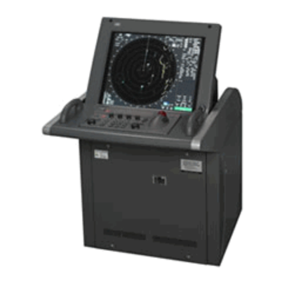
Replacement of Magnetron " S " Band Radar JRC
Make
JRC
Model
JMA-9132-SA
Part Type
M1555
Part Code
5VMAAA00104
1)
Before Starting - Switch off Power to Radar No.1 On the Unit (PIC no 1) and Put No. 2 Radar on "Stby"
Ensure both Scanners are stopped.
In Chart Table on panel "AC EN 100V Dist Panel" Switch Off No 7 - Radar No.1 power Supply.
Put Palacards " Men at Work" on Radar No. 1 & 2 and on ships Whistle
2)
Working Aloft SWCL-003 is required for this Job
Before starting part replacement work, turn off
3)
the Safety Switch of the scanner unit.
4) Remove the pedastal cover
Green and
yellow cable
5)
Remove the cover on the left port side and check that there is no remaining Electric chargeBetween "J2101 Pin 1" and
"J2101 Pin 3" in the modulation circuit board CPA-264
Note - Multimeter requires DC 1000V input capablity.
6)
Remove the 2 screws(M4) holding the Magnetron cables
(both Yelow and Green).
Magnetron
J2101 Pin 1
J2101 Pin 3
Advertisement
Table of Contents

Related Manuals for JRC JMA-9132-SA


Summary of Contents for JRC JMA-9132-SA
- Page 1 Genuine Ace Replacement of Magnetron " S " Band Radar JRC Make Model JMA-9132-SA Part Type M1555 Part Code 5VMAAA00104 Before Starting - Switch off Power to Radar No.1 On the Unit (PIC no 1) and Put No. 2 Radar on "Stby"...
- Page 2 Remove the Eight screws (M6) to remove the fixture holding the magnetron. The screws cannot be removed from the fixture, so losen the eight screws and remove the magnetron together with fixture. Caution:- The Magnetron is held by a hook, but careful not to let it fall Use a Non - Magnetic screw driver.
Need help?
Do you have a question about the JMA-9132-SA and is the answer not in the manual?
Questions and answers
Gyro Heading missing on JMA 9132 SA
The gyro heading is missing on the JRC JMA-9132-SA because the signals from the gyro have stopped. This can occur if the power of the master gyro is turned off or if there is a line failure. When the gyro signal is recovered, a "Set Gyro" alarm will be generated, indicating that the gyro needs to be set again.
This answer is automatically generated
Radar not showing correct range bearing and distance of targets