
Related Manuals for Teknik 5424152


Summary of Contents for Teknik 5424152
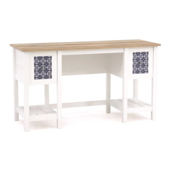
- Page 1 Teknik www.teknikoffice.co.uk For all your newfangled gadgetry. Mediterranean Shaker Style Desk Model 5424152...
- Page 2 Table of Contents Assembly Tools Required Part Identifi cation No. 2 Phillips Screwdriver Tip Shown Actual Size Hardware Identifi cation Assembly Steps 5-27 Hammer Not actual size Troubleshooting Masking Tape Safety 37-38 Scissors Warranty Skip the power trip. This time. Part Identifi...
- Page 3 Now you know Part Identifi cation our ABCs. D151 D953 D151 D953 Page 3...
- Page 4 Hardware Identifi cation å Screws are shown actual size. You may receive extra hardware with your unit. (EXTENSION SET SHOWN SEPARATED) EXTENSION RAIL - 4 EXTENSION SLIDE - 4 35MA 35MC FILE GLIDE - 2 FILE ROD - 2 METAL HIDDEN CAM - 72 CAM DOWEL - 28 CAM SCREW - 44...
- Page 5 Step 1 Assemble your unit on a carpeted fl oor or on the empty å carton to avoid scratching your unit or the fl oor. Push twenty-eight HIDDEN CAMS (1F) into the ENDS (A å and B), UPRIGHTS (C and D), and BOTTOMS (F and G). Then, insert the metal end of a CAM DOWEL (2F) into each HIDDEN CAM.
- Page 6 Step 2 Push forty-four HIDDEN CAMS (1F) into the ENDS (A and B), å UPRIGHTS (C and D), BACKS (H2 and I), and MOLDINGS (S and T). Arrow Arrow (44 used) Arrow Hole The arrow in the HIDDEN CAM must point toward the hole in the edge of the board.
- Page 7 Step 3 Turn forty-four CAM SCREWS (8F) into å the LEGS (K, L, M, N, O, and P). (44 used) Page 7...
- Page 8 Step 4 Turn four BLACK 9/16" FLAT HEAD SCREWS (32S) into å the ENDS (A and B) until the shoulders of the SCREWS Some assembly rest on the surfaces of the ENDS. (and snacks) required. Slide the END MOLDINGS (U) onto the ENDS (A and B). å...
- Page 9 Step 5 Fasten the LEGS (K and M) to a BOTTOM SIDE å MOLDING (T) and the RIGHT END (A). Tighten six HIDDEN CAMS. Fasten the LEGS (L and N) to a BOTTOM SIDE å MOLDING (T) and the LEFT END (B). Tighten six HIDDEN CAMS.
- Page 10 Step 6 Fasten the LEGS (L and O) to a BOTTOM SIDE å MOLDING (T) and the UPRIGHT (C). Tighten six HIDDEN CAMS. Fasten the LEGS (K and P) to a BOTTOM SIDE å MOLDING (T) and the LEFT UPRIGHT (D). Tighten six HIDDEN CAMS.
- Page 11 Step 7 Separate the EXTENSION SLIDES (35MC) from the EXTENSION RAILS (35MA) as shown in the enlarged diagram below. å Be prepared, the parts are greasy. Fasten the EXTENSION RAILS (35MA) to the ENDS (A and B) and UPRIGHTS (C and D). Use eight GOLD 5/16" FLAT å...
- Page 12 Step 8 Insert a WOOD DOWEL (15F) into each short edge of a BOTTOM (F). å Lay two OUTER BOTTOMS (G) next to the BOTTOM (F) as shown. å Fasten two BOTTOM MOLDINGS (S) to the BOTTOMS (F and G). Tighten å...
- Page 13 Step 9 Fasten the MIDDLE REAR LEGS (O and P) to the LARGE å BACK (H2). Tighten four HIDDEN CAMS. Maximum Arrow 210 degrees Fasten the BRACE (J) to the MIDDLE REAR LEGS (O and P). å Use four BLACK 2" PAN HEAD SCREWS (66S). Minimum NOTE: You should start each SCREW a few turns before å...
- Page 14 Step 10 Fasten the SMALL BACKS (I) to the MIDDLE REAR å LEGS (O and P). Tighten four HIDDEN CAMS. Maximum Arrow 210 degrees Fasten a BOTTOM assembly to the LEGS (L and O) å and BOTTOM SIDE MOLDING (T). Tighten four Minimum HIDDEN CAMS.
- Page 15 Step Step 11 Fasten the LEFT END ASSEMBLY to the SMALL å BACK (I) and BOTTOM ASSEMBLY on the left end Maximum Arrow 210 degrees of your unit. Tighten six HIDDEN CAMS. Fasten the RIGHT END ASSEMBLY to the SMALL å...
- Page 16 Step Step 12 NOTE: You will need someone's help in this step. å Maximum Arrow Fasten the TOP (E3) to the ENDS (A and B) and å 210 degrees UPRIGHTS (C and D). Tighten eight HIDDEN CAMS. Fasten three METAL BRACKETS (4G) to the TOP å...
- Page 17 Step 16 BLACK 9/16" LARGE HEAD SCREW (8 used in this step) Tap down with your screwdriver and hammer. Pull the DRAWER FRONT BRACKETS (10G) apart and slide them into the grooves in the DRAWER SIDES (D48 å and D49). You may need to gently tap them in with a hammer. NOTE: The DRAWER FRONT BRACKETS are marked "RH"...
- Page 18 Step 17 Fasten the EXTENSION SLIDES (35MC) to the DRAWER å SIDES (D48 and D49). Use four GOLD 5/16" FLAT HEAD SCREWS (3S) through holes #1 and #3. Fasten a KNOB SET (100K) to the DRAWER FRONT (Q). å Use a SILVER 1/2" MACHINE SCREW (38S). Repeat this step for the other drawer.
- Page 19 Step 18 Push a FILE GLIDE (4B) onto the RIGHT DRAWER SIDE (D48). å Slide the FILE RODS (7B) into the FILE GLIDE (4B) on the å Almost time to RIGHT DRAWER SIDE (D48). celebrate! With a nap. Slide another FILE GLIDE (4B) onto the other end of the å...
- Page 20 Step 19 Carefully stand your unit upright. å To insert the drawers into your unit, line up the EXTENSION SLIDES on the drawer with the EXTENSION RAILS on the unit å and push the drawer into the unit until the drawer is fully inserted. The drawers will push in hard until it is all the way in, then it will slide in and out easier.
- Page 21 WARNING Please use your furniture correctly and safely. Improper use can cause safety hazards, or damage to your furniture or household items. Carefully read the following chart. Look out for: What can happen: How to avoid the problem: • Overloaded shelves and drawers. •...
Need help?
Do you have a question about the 5424152 and is the answer not in the manual?
Questions and answers