Advertisement
Quick Links
Advertisement

Subscribe to Our Youtube Channel
Related Manuals for Teknik 5424259


Summary of Contents for Teknik 5424259
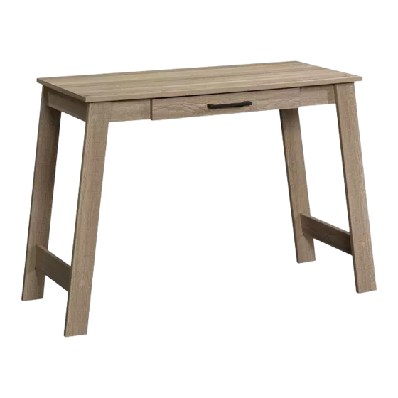
- Page 1 Teknik You could totally write a novel on this. Trestle Desk Model 5424259...
- Page 2 Table of Contents Assembly Tools Required Part Identifi cation No. 2 Phillips Screwdriver Tip Shown Actual Size Hardware Identifi cation Assembly Steps 5-23 Hammer Not actual size Français 24-26 Español 27-29 Short Screwdriver Safety Warranty Skip the power trip. This time. Page 2...
- Page 3 Now you know Part Identifi cation our ABCs. å While not all parts are labeled, some of the parts will have a label or an inked letter on the edge to help distinguish similar parts from each other. Use this part identifi cation to help identify similar parts. TOP (1) W RIGHT UPRIGHT (1) CC LEFT DRAWER SIDE (1)
- Page 4 Hardware Identifi cation CABINET RIGHT - 1 CABINET LEFT - 1 DRAWER RIGHT - 1 DRAWER LEFT - 1 HIDDEN CAM - 8 CAM DOWEL - 8 WOOD DOWEL - 8 APPLIQUE CARD - 1 PULL - 1 GOLD 1-1/2" FLAT HEAD SCREW - 20 GOLD 1/2"...
- Page 5 Step 1 Assemble your unit on a carpeted fl oor or on the empty å carton to avoid scratching your unit or the fl oor. Using a hammer tap eight CAM DOWELS (22) into å the TOP (Q). (8 used) Page 5...
- Page 6 Step 2 Insert eight WOOD DOWELS (23) to the LEGS (Y and Z). å (8 used) Page 6...
- Page 7 Step 3 Push eight HIDDEN CAMS (21) into the ENDS (R) å and UPRIGHTS (V and W). Just think. The sooner you do this, the sooner you do something else. Arrow (8 used) Arrow Hole The arrow in the HIDDEN CAM must point toward the hole in the edge of the board.
- Page 8 Step 4 Fasten the UPRIGHTS (V and W) to the BACK (U). Use å two GOLD 1-1/2" FLAT HEAD SCREWS (26). GOLD 1- 1/2" FLAT HEAD SCREW (2 used in this step) Finished edge f a c Finished edge S u r s u r f a c n i s h...
- Page 9 Step 5 Fasten the FRONTS (S and T) to the UPRIGHTS (V and W). å Use two GOLD 1-1/2" FLAT HEAD SCREWS (26). Finished edge Finished surface Finished edge GOLD 1- 1/2" FLAT HEAD SCREW (2 used in this step) Finished surface Page 9...
- Page 10 Step 6 Fasten the ENDS (R) to the FRONTS (S and T) and BACK (U). å Use four GOLD 1-1/2" FLAT HEAD SCREWS (26). Finished edge U n fi n i s h s u r f a c Finished edge S u r f a c H I D...
- Page 11 Step 7 Fasten the ENDS (R) and the UPRIGHTS (V and W) to å the TOP (Q). Tighten eight HIDDEN CAMS using the short screwdriver. The CAM DOWELS are further from this edge. Page 11...
- Page 12 Step 8 Fasten the CABINET RIGHT (17) to the RIGHT UPRIGHT (W) å and the CABINET LEFT (18) to the LEFT UPRIGHT (V). Use six GOLD 1/2" FLAT HEAD SCREWS (27) through the holes shown in the enlarged diagram. Roller end GOLD 1/2"...
- Page 13 Step 9 Fasten one of each LEG (Y and Z) to the ENDS (R). Use å two GOLD 1-1/2" FLAT HEAD SCREWS (26). Now might be a good time to refresh NOTE: Be sure the WOOD DOWELS in the LEGS insert å...
- Page 14 Step 10 Fasten the LEGS (Y and Z) to the BACK (U). Use four å SILVER 1" PAN HEAD SCREWS (29). Fasten the STRETCHERS (X) to the LEGS (Y and Z). Use å two GOLD 1-1/2" FLAT HEAD SCREWS (26). NOTE: Be sure the WOOD DOWELS in the LEGS insert å...
- Page 15 Step 11 Fasten the remaining LEGS (Y and Z) to the å ENDS (R) and STRETCHERS (X). Use four GOLD 1-1/2" FLAT HEAD SCREWS (26). NOTE: Be sure the WOOD DOWELS in the å LEGS insert into the STRETCHERS and ENDS. GOLD 1- 1/2"...
- Page 16 Step 12 Fasten the LEGS (Y and Z) to the FRONTS (S and T). Use å four SILVER 1" PAN HEAD SCREWS (29). SILVER 1" PAN HEAD SCREW (4 used in this step) Page 16...
- Page 17 Step 13 Fasten the DRAWER BOX FRONT (BB) to the DRAWER å FRONT (AA). Use two SILVER 1" PAN HEAD SCREWS (29) SILVER 1" PAN HEAD SCREW (2 used in this step) Notch Unfi nished edge Page 17...
- Page 18 Step 14 Fasten the PULL to the DRAWER FRONT (AA). Use two å SILVER 1-1/2" PAN HEAD SCREWS (28) through the DRAWER BOX FRONT and DRAWER FRONT. SILVER 1-1/2" PAN HEAD SCREW (2 used in this step) Page 18...
- Page 19 Step 15 Fasten the DRAWER SIDES (CC and DD) to å the DRAWER BOX FRONT (BB). Use two GOLD 1-1/2" FLAT HEAD SCREWS (26). GOLD 1- 1/2" FLAT HEAD SCREW (2 used in this step) Unfi nished edge Notch Page 19...
- Page 20 Step 16 Slide the DRAWER BOTTOM (EE) into the DRAWER å SIDES (CC and DD). NOTE: Be sure the DRAWER BOTTOM inserts into the å DRAWER BOX FRONT. Page 20...
- Page 21 Step 17 Fasten the DRAWER BACK (FF) to the DRAWER SIDES (CC and DD). å Use two GOLD 1-1/2" FLAT HEAD SCREWS (26). If you're doing this to help a friend, don't NOTE: Be sure DRAWER BOTTOM inserts into the DRAWER BACK. å...
- Page 22 Step 18 Fasten the DRAWER RIGHT (19) to the RIGHT DRAWER SIDE (DD) å and the DRAWER LEFT (20) to the LEFT DRAWER SIDE (CC). Use six GOLD 1/2" FLAT HEAD SCREWS (27) through the holes shown. GOLD 1/2" FLAT HEAD SCREW (6 used in this step) Roller end Roller end...
- Page 23 Step 19 Carefully stand your unit upright. å To insert the drawer into your unit, tip the front of the drawer down and drop the rollers on the drawer behind the å rollers on the unit. Lift the front of the drawer up and slide it into the unit. Peel APPLIQUES from the APPLIQUE CARD (25) and stick them onto each visible HIDDEN CAM / SCREW head.
- Page 24 WARNING Please use your furniture correctly and safely. Improper use can cause safety hazards, or damage to your furniture or household items. Carefully read the following chart. Look out for: What can happen: How to avoid the problem: • Overloaded drawers or shelves. •...
Need help?
Do you have a question about the 5424259 and is the answer not in the manual?
Questions and answers