Table of Contents
Advertisement
Quick Links
Advertisement
Table of Contents

Related Manuals for Mitsubishi MELSEC QS Series


Summary of Contents for Mitsubishi MELSEC QS Series
-
Page 3: Safety Precautions
SAFETY PRECAUTIONS (Always read these instructions before using this equipment.) Before using this product, please read this manual, the relevant manuals introduced in this manual, standard PLC manuals, and the safety standards carefully and pay full attention to safety to handle the product correctly. - Page 4 [Design Precautions] DANGER When a safety PLC detects an error in an external power supply or a failure in PLC main module, it turns off all the outputs. Create an external circuit to securely stop the power of hazard by turning off the outputs. Incorrect configuration may result in an accident.
- Page 5 [Installation Precautions] CAUTION Use a safety PLC in the environment that meets the general specifications described in this manual. Using this PLC in an environment outside the range of the general specifications could result in electric shock, fire, erroneous operation, and damage to or deterioration of the product. While pressing the installation lever located at the bottom of module, insert the module fixing tab into the fixing hole in the base unit until it stops.
- Page 6 [Wiring Precautions] CAUTION Be sure to ground the FG terminals and LG terminals to the protective ground conductor. Not doing so could result in electric shock or erroneous operation. Use a solderless terminal with insulation sleeve for wiring of a terminal block. Use up to two solderless terminals for a single terminal.
- Page 7 [Startup and Maintenance precautions] DANGER Do not touch the terminals while power is on. Doing so could cause shock or erroneous operation. Correctly connect the battery. Also, do not charge, disassemble, heat, place in fire, short circuit, or solder the battery. Mishandling of battery can cause overheating or cracks which could result in injury and fires.
- Page 8 [Startup and Maintenance precautions] CAUTION The online operations performed from a PC to a running safety PLC (Program change when a safety CPU is RUN, device test, and operating status change such as RUN-STOP switching) have to be executed after the manual has been carefully read and the safety has been ensured. Following the operating procedure predetermined at designing, the operation has to be performed by an instructed person.
- Page 9 [Disposal Precautions] CAUTION When disposing of this product, treat it as industrial waste. When disposing of batteries, separate them from other wastes according to the local regulations. (For details of the battery directive in EU member states, refer to QSCPU User's Manual (HardwareDesign, Maintenance and Inspection).
-
Page 10: Revisions
This manual confers no industrial property rights or any rights of any other kind, nor does it confer any patent licenses. Mitsubishi Electric Corporation cannot be held responsible for any problems involving industrial property rights which may occur as a result of using the contents noted in this manual. -
Page 11: Table Of Contents
INTRODUCTION Thank you for choosing the Mitsubishi MELSEC-QS Series of Safety Programmable Controllers. Before using the equipment, please read this manual carefully to develop full familiarity with the functions and performance of the QS series PLC you have purchased, so as to ensure correct use. - Page 12 CHAPTER4 I/O NUMBER ASSIGNMENT 4 - 1 to 4 - 9 Definition of I/O Number •••••••••••••••••••••••••••••••••••••••••••••••••••••••••••••••••••••••••••••••••••••••••••4 - 1 Concept of I/O Number Assignment ••••••••••••••••••••••••••••••••••••••••••••••••••••••••••••••••••••••••••••4 - 2 4.2.1 I/O numbers of base unit•••••••••••••••••••••••••••••••••••••••••••••••••••••••••••••••••••••••••••••••••••••4 - 2 4.2.2 I/O numbers of remote station ••••••••••••••••••••••••••••••••••••••••••••••••••••••••••••••••••••••••••••••4 - 2 I/O Assignment by GX Developer •••••••••••••••••••••••••••••••••••••••••••••••••••••••••••••••••••••••••••••••4 - 4 4.3.1 Purpose of I/O assignment by GX Developer••••••••••••••••••••••••••••••••••••••••••••••••••••••••••••4 - 4...
- Page 13 6.10 Setting of Output (Y) Status when Changing between STOP and RUN ••••••••••••••••••••••••••••••• 6 - 42 6.11 Clock Function••••••••••••••••••••••••••••••••••••••••••••••••••••••••••••••••••••••••••••••••••••••••••••••••••••• 6 - 45 6.12 Remote Operation •••••••••••••••••••••••••••••••••••••••••••••••••••••••••••••••••••••••••••••••••••••••••••••••• 6 - 48 6.12.1 Remote RUN/STOP •••••••••••••••••••••••••••••••••••••••••••••••••••••••••••••••••••••••••••••••••••••••• 6 - 48 6.12.2 Remote RESET•••••••••••••••••••••••••••••••••••••••••••••••••••••••••••••••••••••••••••••••••••••••••••••• 6 - 51 6.12.3 Relationship of remote operation and CPU's RUN/STOP status ••••••••••••••••••••••••••••••••••...
- Page 14 9.3.2 Special register (SD)•••••••••••••••••••••••••••••••••••••••••••••••••••••••••••••••••••••••••••••••••••••••• 9 - 33 Nesting (N) ••••••••••••••••••••••••••••••••••••••••••••••••••••••••••••••••••••••••••••••••••••••••••••••••••••••••• 9 - 34 Constants••••••••••••••••••••••••••••••••••••••••••••••••••••••••••••••••••••••••••••••••••••••••••••••••••••••••••• 9 - 35 9.5.1 Decimal constant (K) ••••••••••••••••••••••••••••••••••••••••••••••••••••••••••••••••••••••••••••••••••••••• 9 - 35 9.5.2 Hexadecimal constant (H) ••••••••••••••••••••••••••••••••••••••••••••••••••••••••••••••••••••••••••••••••• 9 - 35 CHAPTER10 CPU MODULE PROCESSING TIME 10 - 1 to 10 - 7 10.1 Scan Time ••••••••••••••••••••••••••••••••••••••••••••••••••••••••••••••••••••••••••••••••••••••••••••••••••••••••••...
-
Page 15: Contents
(Related manual)....QSCPU User's Manual (Hardware Design, Maintenance and Inspection) CONTENTS CHAPTER1 OVERVIEW Features CHAPTER2 SYSTEM CONFIGURATION System Configuration 2.1.1 Precautions for system configuration Configuration of Peripheral Devices Confirming Serial No. and Function Version CHAPTER3 GENERAL SPECIFICATIONS CHAPTER4 CPU MODULE Performance Specifications Part Names Switch Operation after Writing a Program... - Page 16 CHAPTER9 EMC AND LOW VOLTAGE DIRECTIVES Requirements for Conformance to EMC Directive 9.1.1 Standards relevant to the EMC Directive 9.1.2 Installation instructions for EMC Directive 9.1.3 Cables 9.1.4 Power Supply Module 9.1.5 Others Requirement to Conform to the Low Voltage Directive 9.2.1 Standard applied for MELSEC-QS series PLC 9.2.2...
- Page 17 12.2.8 When the "USER" LED is on 12.2.9 When the "BAT." LED is on 12.2.10 Flowchart for when a program cannot be read 12.2.11 Flowchart for when a program cannot be written 12.3 Error Code List 12.3.1 Error codes 12.3.2 Reading an error code 12.3.3 Error code list (1000 to 1999)
-
Page 18: About Manuals
ABOUT MANUALS Introduction Manual Before constructing or designing the safety-related system, be sure to read the following manual. Manual No. Manual Name (Model Code) Safety Application Guide SH-080613ENG Explains the overview, construction method, laying and wiring examples, and application programs of the (13JR90) safety-related system. - Page 19 Manual Number Manual Name (Model Code) Q Corresponding MELSEC Communication Protocol Reference Manual Explains the communication methods and control procedures using the MC protocol, which is used by external SH-080008 devices to read and write data of the programmable controller CPU via the serial communication module or (13JF89) Ethernet module.
-
Page 20: How To See This Manual Is Organized
HOW TO SEE THIS MANUAL IS ORGANIZED Reference destination Chapter heading A reference destination or The index on the right side of the page reference manual is marked shows the chapter of the open page at a glance. Section title The section of the open page is shown at a glance. - Page 21 In addition, this manual provides the following explanations. POINT Explains the matters to be especially noted, the functions and others related to the description. Remark Provides the reference destination related to the description on that page and the convenient information. - 19...
-
Page 22: How To Use This Manual
HOW TO USE THIS MANUAL This manual is prepared for users to understand memory map, functions, programs and devices of the CPU module when you use QS Series PLCs. The manual is classified roughly into three sections as shown below. 1) Chapters 1 Describe the outline of the CPU module. -
Page 23: Generic Terms And Abbreviations
Other name for the Q series CPU module (Used for distinction from safety CPU Standard CPU module modules) Battery Abbreviation for the Q6BAT type battery Blank cover Abbreviation for the QG60 type blank cover Generic term for the Mitsubishi Graphic Operation Terminal GOT-A*** series, GOT-F*** series and GOT1000 series - 21... - Page 24 Memo - 22...
-
Page 25: Chapter1 Overview
OVERVIEW CHAPTER1 OVERVIEW This manual describes the programs, I/O number assignment method, functions and devices of the QS Series CPU Modules (QS001CPU). For the power supply modules, base units and batteries, refer to the manual below. QSCPU User's Manual (Hardware Design, Maintenance and Inspection) - Page 26 OVERVIEW (1) List of QS Series CPU Module manuals The QS series CPU module manuals are as shown below. For details such as manual numbers, refer to "ABOUT MANUALS" in this manual. Table1.1 List of manuals of QS Series CPU module Hardware Maintenance Program...
-
Page 27: Features
OVERVIEW 1.1 Features The QS series CPU module has the following new features: (1) Safety PLC system can be constructed The QS series programmable controllers have obtained the highest safety level (IEC61508 SIL3, EN954-1/ISO13849-1 Category 4, IEC62061) applicable to programmable controllers. Power supply/CPU/CC-Link Safety master module CC-Link Safety remote I/O station CC-Link Safety... - Page 28 OVERVIEW (2) The safety CPU operation mode is equipped for safe system operation The CPU module is equipped with two safety CPU operation modes. "SAFETY MODE" for safe system operation and "TEST MODE" for system construction and maintenance. These two modes prevent the user's erroneous operations for safe system operation. (a) SAFETY MODE SAFETY MODE is a mode for safe system operation.
- Page 29 OVERVIEW (4) Enhanced RAS (a) Enhanced memory diagnostics The memory diagnostics equipped with the CPU module are enhanced. (b) Redundant CPU The CPU module has two CPUs (CPU A and CPU B). The operation results of CPU A/CPU B are compared, and output only when the results are matched so that incorrect outputs can be prevented.
- Page 30 OVERVIEW (5) USB interface is equipped The CPU module is equipped with the USB interface to communicate with a programming tool. Personal computer Figure 1.3 Connection to a personal computer using USB (6) Connectable with personal computers and standard programmable controllers The CPU module can read data from the MELSOFT products installed in the personal computer and also can communicate data between safety programmable controller...
-
Page 31: Program Storage And Operation
OVERVIEW 1.2 Program Storage and Operation (1) Program storage (a) Storage of program created by GX Developer The program created by GX Developer can be stored into the program memory or standard ROM of the CPU module.Note1 Program memory Parameter Program Device comment Standard ROM... - Page 32 OVERVIEW (c) Execution of program stored in standard ROM Programs and data can also be stored into the standard ROM. The programs stored in the standard ROM can be booted (read) to the program memory and executed when the PLC is powered ON or the CPU module is reset.Note2 Execution of program booted from the standard ROM to the program memory.
-
Page 33: Devices And Instructions Convenient For Programming
OVERVIEW 1.3 Devices and Instructions Convenient for Programming The CPU module has devices and instructions convenient for program creation. The main devices and instructions are outlined below. (1) Flexible device designation CPU modules allow devices to be specified flexibly. (a) Word device bits are handled as contacts/coils By specifying the bit of the word device, each bit of the word device can be handled as a contact/coil. -
Page 34: How To Check The Serial No. And Function Version
OVERVIEW 1.4 How to Check the Serial No. and Function Version The serial No. and function version of the CPU module can be checked on the rating plate or in the system monitor of GX Developer. (1) Checking on rating plate The rating plate is on the side face of the CPU module. - Page 35 OVERVIEW (3) Confirming the serial No. on the system monitor (Product Information List) To display the System monitor screen, select [Diagnostics] [System monitor] and click the Product Information List button in GX Developer. On the system monitor, the serial No. and function version of the intelligent function module can also be confirmed.
-
Page 36: Chapter2 Performance Specification
PERFORMANCE SPECIFICATION CHAPTER2 PERFORMANCE SPECIFICATION Table2.1 shows the performance specifications of the CPU module. Table2.1 Performance Specifications Item QS001CPU Remarks Control method Repetitive operation of stored program ---- I/O control mode ---- Refresh mode Program Sequence control Relay symbol language, function block. ---- language language... - Page 37 PERFORMANCE SPECIFICATION Table2.1 Performance Specifications (Continue) Item QS001CPU Remarks Internal relay [M] 6144 points by default (M0-6143) (changeable) Link relay [B] 2048 points by default (B0 to 7FF) (changeable) 512 points by default (T0 to 511) (changeable) (Sharing of low- and high-speed timers) The low- and high-speed timers are specified by the instructions.
-
Page 38: Chapter3 Sequence Program Execution
SEQUENCE PROGRAM EXECUTION CHAPTER3 SEQUENCE PROGRAM EXECUTION The CPU module executes a program in the following order Initial processing I/O refresh Program operation processing END processing Diagram 3.1 Program execution order... -
Page 39: Sequence Program
SEQUENCE PROGRAM EXECUTION 3.1 Sequence Program A sequence program is created using the sequence instructions, basic instructions, application instructions, etc. Sequence instruction X100 K100 Y100 Basic instruction X140 BIN K4X120 Application X141 instruction WAND D0 Diagram 3.2 Sequence program Remark Refer to the following manual for the sequence instructions, basic instructions and application instructions. -
Page 40: Sequence Program Description Method
SEQUENCE PROGRAM EXECUTION 3.1.1 Sequence program description method The sequence program is created with the ladder mode of GX Developer. The ladder mode is based on the concept of a sequence circuit of relay control. It enables programming in representation close to a sequence circuit. In the ladder mode, programming is performed in ladder block units. -
Page 41: Sequence Program Operation
SEQUENCE PROGRAM EXECUTION 3.1.2 Sequence program operation The CPU module calculates in order from the left to the right side vertical bus and from top to bottom. [Ladder mode] From left to right X100 X101 X105 X106 X107 Y110 From top X102 X103 to bottom X104... -
Page 42: Concept Of Scan Time
SEQUENCE PROGRAM EXECUTION 3.2 Concept of Scan Time (1) Scan time Scan time is a period from the time when the CPU module starts the sequence program operation from Step 0 until it executes Step 0 of the same sequence program again. - Page 43 SEQUENCE PROGRAM EXECUTION (2) WDT (Watchdog timer) The watchdog timer (hereafter abbreviated to the WDT) watches the scan time. The default value is 200ms. (a) WDT error A WDT error is 10ms. When the WDT (t) is set to 10ms, a "WDT ERROR" occurs within a scan time range of 10ms<t<20ms.
-
Page 44: Operation Processing
SEQUENCE PROGRAM EXECUTION 3.3 Operation Processing This section explains the operation processing of the CPU module. 3.3.1 Initial processing Initial processing is a preprocessing for execution of the sequence program operation. When the PLC is power-on or the CPU module reset is canceled, the following processing is executed only once. -
Page 45: I/O Refresh
SEQUENCE PROGRAM EXECUTION 3.3.2 I/O refresh I/O data between CC-Link Safety master module and network module are refreshed by I/O refresh. The I/O refresh is executed before the sequence program operation starts. 3.3.3 END processing This is a post-processing to return the sequence program execution to step 0 after completing the whole sequence program operation processing once. -
Page 46: Run, Stop Operation Processing
SEQUENCE PROGRAM EXECUTION 3.4 RUN, STOP Operation Processing CPU module has two types of operation status; RUN and STOP status. CPU module operation processing is explained below: (1) RUN Status Operation Processing RUN status indicate that the sequence program operation is performed from step 0 to END instruction to step 0 repeatedly. - Page 47 SEQUENCE PROGRAM EXECUTION (3) CPU module operation processing at switch operation Note3 Table3.1 Operation processing at switch operation CPU module operation processing Sequence Device memory RUN/STOP program status External output operation M,T,C,D processing Saves the output (Y) Saves the output (Y) Executes up to Saves the device memory status immediately...
-
Page 48: Operation Processing During Momentary Power Failure
SEQUENCE PROGRAM EXECUTION 3.5 Operation Processing during Momentary Power Failure When the input voltage supplied to the power supply module drops below the specified range, the CPU module detects a momentary power failure and performs the following operation. (1) When momentary power failure occurs for a period shorter than the permitted power failure time The output is maintained when the momentary power failure occurs, and error history are logged. -
Page 49: Data Clear Processing
SEQUENCE PROGRAM EXECUTION 3.6 Data Clear Processing This section explains how to clear CPU module data (1) Data clear methods There are the following six ways to clear CPU module data. (a) Reset with the RUN/STOP/RESET switch, GX Developer. (b) Restarting the PLC System (c) PLC memory clear using GX Developer (d) PLC memory format using GX Developer (e) PLC memory initialization using GX Developer... -
Page 50: Numeric Values Which Can Be Used In Sequence Programs
SEQUENCE PROGRAM EXECUTION 3.7 Numeric Values which can be Used in Sequence Programs Numeric and alphabetic data are expressed by "0" (OFF) and "1" (ON) numerals in the CPU module. This expression form is called "binary code" (BIN). The hexadecimal (HEX) expression form in which BIN data are expressed in 4-bit units, and the BCD (binary coded decimal) expression form are applicable to the CPU module. - Page 51 SEQUENCE PROGRAM EXECUTION (1) Numeric value input from outside to CPU module When setting a numeric value from an external digital switch or similar device to the CPU module, BCD (binary coded decimal) can be used as the same setting in DEC (decimal) by the method given in (b).
- Page 52 SEQUENCE PROGRAM EXECUTION (2) Numeric value output from CPU module to outside A digital display or similar device is available to externally display the numeric value operated by the CPU module. (a) How to output numeric value The CPU module performs operation in BIN. If binary values used in the CPU module are output as they are to a digital display, they will not displayed correctly.
-
Page 53: Bin (Binary Code)
SEQUENCE PROGRAM EXECUTION 3.7.1 BIN (Binary Code) (1) Binary code Binary date is represented by 0 (OFF) and 1 (ON). Decimal notation uses the numerals 0 through 9. When counting beyond 9, a 1 is placed in the 10s column and a 0 is placed in the 1s column to make the number 10. In binary notation, the numerals 0 and 1 are used. -
Page 54: Hex (Hexadecimal)
SEQUENCE PROGRAM EXECUTION 3.7.2 HEX (Hexadecimal) (1) Hexadecimal notation In hexadecimal notation, 4 binary bits are expressed in 1 digit. If 4 binary bits are used in binary notation, 16 different values from 0 to 15 can be represented. Since hexadecimal notation represents 0 to 15 in 1 digit, letters A to F are used to represent the numbers 10 to 15. -
Page 55: Bcd (Binary Coded Decimal)
SEQUENCE PROGRAM EXECUTION 3.7.3 BCD (Binary Coded Decimal) (1) BCD notation BCD (binary coded decimal) is a numbering system in which one digit of DEC (decimal) is expressed in BIN (binary). Though it uses 4-bit representation like hexadecimal notation, it dose not use letters to F Table3.6 shows the numeric expressions of BIN, BCD and DEC. -
Page 56: Chapter4 I/O Number Assignment
I/O NUMBER ASSIGNMENT CHAPTER4 I/O NUMBER ASSIGNMENT This chapter explains the I/O number assignment required for the CPU module to communicate data with I/O modules and/or intelligent function modules. 4.1 Definition of I/O Number I/O numbers indicate the addresses used in a sequence program to input or output ON/ OFF data between the CPU module and other modules. -
Page 57: Concept Of I/O Number Assignment
I/O NUMBER ASSIGNMENT 4.2 Concept of I/O Number Assignment 4.2.1 I/O numbers of base unit The CPU module assigns I/O numbers when the programmable controller is powered ON or the reset operation of the CPU module is performed. I/O numbers are assigned automatically from the right side of the CPU module of the main base unit. - Page 58 I/O NUMBER ASSIGNMENT [System configuration] CC-Link Safety CC-Link Safety Remote station Remote station Remote station Remote station [I/O number assignment] Input/output(X/Y) X/Y0 I/O numbers assigned to the CC-Link Safety master modules and CC-Link IE controller network module X/Y5F Empty X/Y100 Refresh destination for the first CC-Link Safety master module...
-
Page 59: I/O Assignment By Gx Developer
I/O NUMBER ASSIGNMENT 4.3 I/O Assignment by GX Developer This section describes the I/O assignment using GX Developer. 4.3.1 Purpose of I/O assignment by GX Developer Perform I/O assignment setting by GX Developer in the following cases. (1) Preventing I/O numbers from changing when converting modules You can avoid the change in the intelligent function module is removed due to a malfunction. -
Page 60: Concept Of I/O Assignment Using Gx Developer
I/O NUMBER ASSIGNMENT 4.3.2 Concept of I/O assignment using GX Developer In I/O assignment, the "Type (module type)", "Points (I/O points)" and "Start XY" (starting I/ O number) can be set for each slot of the base units. For example, to change the number of occupied I/O points of the designated slot, only the number of occupied I/O points can be designated. - Page 61 I/O NUMBER ASSIGNMENT (c) Model name Set the mounted module model name within 16 characters. The specified model name is not used for the CPU module. (It is used as a user's memo.) (d) Points To change the number of occupied I/O points of each slot, select it from the followings: •...
- Page 62 I/O NUMBER ASSIGNMENT 3) Last I/O number In I/O assignment, set the last I/O number not to exceed the maximum value CHAPTER 2) of the I/O points. An error ("MODULE LAYOUT ERROR") will occur if the last I/O number exceeds the maximum value of the I/O points. (System monitor of GX Developer shows "***"...
-
Page 63: Examples Of I/O Number Assignment
I/O NUMBER ASSIGNMENT 4.3.3 Examples of I/O Number Assignment This section shows an I/O number assignment example when I/O assignment is set in GX Developer. (1) When setting the number of I/O points for mounted modules Set 32 points for the slots where CC-Link Safety master module or CC-Link IE controller network module is mounted so that the I/O numbers do not change even when the module is removed due to the breakdown of CC-Link Safety master module or CC-Link IE controller network module. -
Page 64: Checking The I/O Numbers
I/O NUMBER ASSIGNMENT 4.4 Checking the I/O Numbers The modules mounted on the main base unit and their I/O numbers can be checked using the GX Developer system monitor. ( Section 6.17) 4.4 Checking the I/O Numbers 4.3.3 Examples of I/O Number Assignment... -
Page 65: Chapter5 Memories And Files Handled By Cpu Module
MEMORIES AND FILES HANDLED BY CPU MODULE CHAPTER5 MEMORIES AND FILES HANDLED BY CPU MODULE 5.1 Memories by CPU Module 5.1.1 Memory configuration and storable data This section explains the memories handled by the CPU module and the data that can be stored into the memories. - Page 66 MEMORIES AND FILES HANDLED BY CPU MODULE (2) Data that can be stored into memories Table5.1 indicates the data that can be stored into the program memory, standard RAM and standard ROM and the corresponding drive Nos. Table5.1 Storable data and storage locations CPU module built-in memories File name and Drive No.
-
Page 67: Program Memory
MEMORIES AND FILES HANDLED BY CPU MODULE 5.1.2 Program memory (1) Definition of program memory The program memory stores the program used by the CPU module to perform operation. The program stored in the standard ROM is booted (read) to the program memory to perform operation. - Page 68 MEMORIES AND FILES HANDLED BY CPU MODULE (b) Create a user setting system area When formatting the program memory, set the user setting system area capacity. 1) Do not create a user setting system area The program memory is formatted without the user setting system area being created.
- Page 69 MEMORIES AND FILES HANDLED BY CPU MODULE (c) Checking the memory capacity after formatting To check the memory capacity, choose [Online] [Read from PLC] on GX Developer. 1) Select "Program memory/Device memory" as the target memory on the Read from PLC screen. 2) Click the button.
- Page 70 MEMORIES AND FILES HANDLED BY CPU MODULE (4) Write to program memory When writing data to program memory, display the writing to PLC screen with GX Developer [Online] [Write to PLC]. Select "Program memory/Device memory" as the target memory on the Write to PLC screen and write data to the PLC.
-
Page 71: Standard Rom
MEMORIES AND FILES HANDLED BY CPU MODULE 5.1.3 Standard ROM (1) Definition of standard ROM The standard ROM is used to execute boot run by the CPU module. The standard ROM is used to save programs and parameters without battery backup. The program stored in the standard ROM is booted (read) to the program memory Section 5.1.2) to perform operation. - Page 72 MEMORIES AND FILES HANDLED BY CPU MODULE (4) Write to standard ROM For details on writing to the standard ROM, refer to Section 5.1.4 (3). POINT The file size has the minimum unit. ( Section 5.3.4) The occupied memory capacity may be greater than the actual file size. (5) How to use the program stored in the standard ROM Since operation cannot be executed by the program stored in the standard ROM, use that program by booting (reading) it to the program memory.
-
Page 73: Standard Rom Program Execution (Boot Run) And Writing
MEMORIES AND FILES HANDLED BY CPU MODULE 5.1.4 Standard ROM program execution (boot run) and writing (1) Standard ROM program execution (boot run) (a) Standard ROM program execution The CPU module performs operation of the program stored in the program memory. - Page 74 MEMORIES AND FILES HANDLED BY CPU MODULE (2) Procedure up to boot run and stopping boot run (in TEST MODE) (a) Procedure for boot run The following provides the procedure for boot run. 1) Program creation by GX Developer Create a program for executing boot run. 2) Boot file by GX Developer Set "Do boot from Standard ROM"...
- Page 75 MEMORIES AND FILES HANDLED BY CPU MODULE 3) Write to standard ROM by GX Developer • Choose [Online] [Write to PLC] on GX Developer and write the files to the program memory. • Choose [Online] [Write to PLC (Flash ROM)] [Write the program memory to ROM...] on GX Developer, and write to the standard ROM the files written to the program memory.
- Page 76 MEMORIES AND FILES HANDLED BY CPU MODULE (3) Write to standard ROM The program memory files are written to the standard ROM by batch-copying them to the standard ROM. (a) Before write Check the following points before writing the files to the standard ROM. 1) Saving the standard ROM files When files are written to the standard ROM, all files previously stored in the standard ROM are automatically deleted.
- Page 77 MEMORIES AND FILES HANDLED BY CPU MODULE (4) Additions/changes to standard ROM files (in TEST MODE) Since all files stored in the standard ROM are automatically deleted when files are to be written to the standard ROM, additions/changes to the stored files cannot be made directly.
-
Page 78: Program File Structure
MEMORIES AND FILES HANDLED BY CPU MODULE 5.2 Program File Structure A program file consists of a file header, execution program and allocate memory for online change. Program file structure 34 steps File header (dafult) Execution program Area is secured in file size units. Section 5.3.4 Allocate memory 500 steps... - Page 79 MEMORIES AND FILES HANDLED BY CPU MODULE (2) Display of program capacity by GX Developer During programming by GX Developer, the program capacity (sum of the file header capacity and the numbers of steps in the created program) is displayed in terms of the number of steps as shown in Diagram 5.10.
-
Page 80: File Operation By Gx Developer And Handling Precautions
MEMORIES AND FILES HANDLED BY CPU MODULE 5.3 File Operation by GX Developer and Handling Precautions 5.3.1 File operation The files stored in program memory and the standard ROM can be operated with GX Developer online operations. However, the file operations that can be executed depend on the safety CPU operation mode and the CPU module RUN/STOP status. -
Page 81: Memory Capacities Of Files
MEMORIES AND FILES HANDLED BY CPU MODULE 5.3.3 Memory capacities of files When using the program memory or standard ROM, calculate the rough size of each file according to Table5.4. Table5.4 Memory capacity calculation for files Function Rough file capacity (unit: byte) Drive heading Default: 316 (increases depending on the parameter setting) Reference... -
Page 82: File Size Units
MEMORIES AND FILES HANDLED BY CPU MODULE 5.3.4 File size units (1) What is file size unit? The minimum unit for writing a file to a memory area is called as a file size unit. The CPU module file size unit is 4 bytes. Program memory, Standard ROM The area is secured in 4-byte unit. -
Page 83: Chapter6 Functions
FUNCTIONS CHAPTER6 FUNCTIONS Function of CPU module is as follows: 6.1 Function List Functions of CPU module are listed in Table6.1. The Nos. in the "CPU module" field correspond to the CPU modules as indicated below. Table6.1 CPU module function list Safety CPU operation mode Reference... -
Page 84: Safety Cpu Operation Mode
FUNCTIONS 6.2 Safety CPU Operation Mode 6.2.1 Safety CPU operation mode The safety CPU operation mode has "SAFETY MODE" and "TEST MODE". Switch the safety CPU operation mode by operations from GX Developer. (1) SAFETY MODE This mode is used for the main operation of the safety-related system. In SAFETY MODE, to protect this system while it is operating, operations that change safety PLC control, such as writing to PLC and device test, are prohibited. -
Page 85: Safety Cpu Operation Mode
FUNCTIONS (2) TEST MODE This mode is used for system start-up and maintenance. In this mode, all the GX Developer functions, such as PLC writing and device testing, can be used. CPU module (Execute the program operations) CC-Link Safety master module Program Program, parameters, and... - Page 86 FUNCTIONS (3) Safety CPU operation mode switching Diagram 6.3 shows the state when the safety CPU operation mode is switched. At the factory When safety CPU operation mode becomes unstable due to low battery voltage. SAFETY MODE PLC power-on CPU module reset Safety CPU operation mode switching cancel (SAFETY MODE to TEST MODE)
-
Page 87: Checking Safety Cpu Operation Mode
FUNCTIONS 6.2.2 Checking safety CPU operation mode The safety CPU operation mode of the CPU module can be checked with the following methods. • Checking with the LEDs on the front of the CPU module • Checking with the GX Developer online operation screen •... - Page 88 FUNCTIONS (2) Checking with the GX Developer online operation screen The current safety CPU operation mode of the CPU module is displayed on the GX Developer online operation screen (PLC diagnostics, remote operation, etc.) The safety CPU operation mode can be checked when executing remote operations etc.
- Page 89 FUNCTIONS (3) Checking with a special relay or a special register The current safety CPU operation mode is stored in the special relay SM560 (TEST MODE flag) and special register SD560 (safety CPU operation mode) in the CPU module. The safety CPU operation mode can be externally displayed using SM560 or SD560 in a program.
-
Page 90: Safety Cpu Operation Mode Switching
FUNCTIONS 6.2.3 Safety CPU operation mode switching To switch the safety CPU operation mode, execute the GX Developer "safety CPU operation mode switching" operation. (1) Safety CPU operation mode switching conditions The safety CPU operation mode can be switched in the states shown in Table6.4. Table6.4 Conditions under which the safety CPU operation mode can be switched TEST MODE to SAFETY MODE to... - Page 91 FUNCTIONS (2) Safety CPU operation mode switching procedure This explains the procedure for switching the safety CPU operation mode by operating the GX Developer "safety CPU operation mode switching". (a) TEST MODE to SAFETY MODE switching Diagram 6.5 shows the procedure for TEST MODE to SAFETY MODE switching using GX Developer.
- Page 92 FUNCTIONS Are the programs and parameters of GX Developer the same with those of program memory? Stopping switching TEST MODE to SAFETY MODE Click the OK button. Are the parameters and programs of the program memory and those of standard ROM the same? Continued to the next page Checking completion of the switch to SAFETY MODE Click the OK button.
- Page 93 FUNCTIONS Select copying program memory data into ROM Click the Yes button. Execute copying program memory data into ROM Click the OK button. Checking completion of the switch to SAFETY MODE Click the OK button. SAFETY MODE (wait-for-restart) You can return to TEST MODE by switching the safety CPU operation mode using GX Developer Switching the safety CPU operation mode using GX Developer enables to return to the TEST...
- Page 94 FUNCTIONS (b) SAFETY MODE to TEST MODE switching Diagram 6.6 shows the procedure for SAFETY MODE to TEST MODE switching using GX Developer. Start Set the CPU module to STOP Set the CPU module RUN/STOP/RESET switch to the STOP position Display safety CPU operation mode screen The safety CPU operation mode screen is displayed with the following operations.
- Page 95 FUNCTIONS Check the completion of the switch to TEST MODE Click the OK button. Completed Figure 6.6 SAFETY MODE to TEST MODE switching (continued) 6.2 Safety CPU Operation Mode - 13 6.2.3 Safety CPU operation mode switching...
-
Page 96: Operation Of Each Function In Each Safety Cpu Operation Mode And Cpu Operation Status
FUNCTIONS 6.2.4 Operation of each function in each safety CPU operation mode and CPU operation status Table6.5 shows whether each function can be executed or not in each safety CPU operation mode and CPU operation status. Table6.5 Whether each function can be executed or not in each safety CPU operation mode and CPU operation status Safety CPU operation mode Test mode during... - Page 97 FUNCTIONS Safety mode (wait-for-restart) Safety mode during during During During STOP Stop error STOP Stop error switching switching initial initial from STOP from STOP status status status status processing processing to RUN to RUN (OFF output) (OFF output) (OFF output) (OFF output) : The function operates.
-
Page 98: Online Operations That Can Be Executed On The Cpu Module From Gx Developer
FUNCTIONS 6.2.5 Online operations that can be executed on the CPU module from GX Developer Table6.6 shows the online operations that can be executed on the CPU module from GX Developer. Table6.6 Online operations that can be executed on the CPU module from GX Developer Safety CPU operation mode Test mode during... - Page 99 FUNCTIONS Safety mode (wait-for-restart) Safety mode during during During During STOP Stop error STOP Stop error switching switching initial initial from STOP from STOP status status status status processing processing to RUN to RUN : The function operates. : The function does not operate. -: This combination does not exist. * 1: Indicates the stop error due to moderate error or severe error.
-
Page 100: Cpu Access Password
FUNCTIONS 6.3 CPU access password (1) What a CPU access password is To prevent incorrect operations from a GX Developer connected by mistake, the CPU module authenticates access using a password. This password for authenticating access is called as the CPU access password. The CPU access password must be set in both the GX Developer project and the CPU module. - Page 101 FUNCTIONS (2) CPU access password setting and characters that can be used (a) CPU access password setting The CPU access password is set on the CPU access password registration/ change screen of GX Developer. The CPU access password set is registered in the project. For details on CPU access password registration/change operations, refer to the GX Developer Manual (Safety PLC).
- Page 102 FUNCTIONS (b) Types and number of characters that can be used for CPU access passwords Set a CPU access password made up of 6 - 14 single-byte Latin letters, numbers, and symbols (the shaded section of Table6.7). (Uppercase and lowercase letters are differentiated.) Table6.7 Characters that can be used for CPU access passwords 0000 (SP)
-
Page 103: Plc Memory Initialization
FUNCTIONS 6.4 PLC memory initialization (1) What PLC memory initialization is PLC memory initialization erases user data written in the CPU module. When you initialize the PLC memory, data is returned to its factory settings. After PLC memory initialization is executed, the system automatically resets cancels the reset, then the initialization processing is executed again. - Page 104 FUNCTIONS (3) PLC memory initialization execution possible/not possible PLC memory initialization can be executed in the following cases. SAFETY MODE Safety CPU operation mode SAFETY MODE TEST MODE (wait-for-restart) CPU operation status STOP STOP STOP PLC memory initialization execution possible/not possible : Can be executed, : Cannot be executed...
- Page 105 FUNCTIONS (4) PLC memory initialization procedure Diagram 6.10 shows the PLC memory initialization procedure with GX Developer. Start Set the CPU module to the STOP status. Set the CPU module RUN/STOP/RESET switch to the STOP position. Display PLC memory initialization screen. The PLC memory initialization screen is displayed with the following operations.
- Page 106 FUNCTIONS During PLC memory initialization The "ALIVE" LED on the front of the CPU module lights up and the other LEDs flash. Flashing ALIVE TEST USER ERR. BAT. PLC memory initialization completed The "ALIVE" LED on the front of the CPU module lights up and "ERR."...
-
Page 107: Setting To Prevent Continuous Run In Test Mode
FUNCTIONS 6.5 Setting to prevent continuous RUN in TEST MODE (1) What the setting to prevent continuous RUN in TEST MODE is The setting to prevent continuous RUN in TEST MODE is for preventing a continuous RUN for a long time in TEST MODE. If the RUN state in TEST MODE exceeds the restriction time (continuous RUN tolerance time in TEST MODE), the "TEST MODE TIME EXCEEDED"... - Page 108 FUNCTIONS (3) Setting the TEST MODE continuous RUN tolerance time The continuous RUN tolerance time in TEST MODE is set with the PLC parameter safety setting screen. Setting the continuous RUN tolerance time in TEST MODE Settable range: 1 to 86400 (1 to 86,400 seconds) Default: 10 (10 seconds) Diagram 6.12 PLC parameter safety setting screen (4) Checking the continuous RUN operation time in TEST MODE...
-
Page 109: Checking The Rom Write Count
FUNCTIONS 6.6 Checking the ROM write count The ROM write count is up to 100,000. When the ROM write count exceeds 100,000, the continuation error "EXCEED MAX FLASH ROM REWRIT. ERR." (error code: 1610) occurs. When the [EXCEED MAX FLASH ROM REWRIT. ERR.] (error code: 1610) occurs, the CPU may not write to the ROM, which needs to replace the CPU module. -
Page 110: Self-Diagnostics Function
FUNCTIONS 6.7 Self-diagnostics Function (1) What the self-diagnostics function is The self-diagnostics function diagnoses presence or absence of an error in the CPU module by itself. The objectives of the self-diagnostics function are the prevention of malfunction of the CPU module and preventive maintenance. (2) Self-diagnostics timing If an error occurs when the CPU module is power on or while the CPU module is running, the self-diagnostics function detects and displays the error, and executes the... - Page 111 FUNCTIONS (6) List of self-diagnostics The error messages in the "Error message" column in the table can be checked on the screen displayed by selecting [Diagnostics] [PLC Diagnostics] in GX Developer. Table6.11 List of self-diagnostics Detailed item/ Diagnostics Error occurring when error is detected Diagnostics description Diagnostics subject timing...
- Page 112 FUNCTIONS Table 6.11 Self-diagnostics list (continued) Detailed item/ Diagnostics Error occurring when error is detected Diagnostics description Error code Error message Diagnostics subject timing • At power ON • At rese • When accessing 1401 Module state during Checks that the CC-Link Safety master module to intelligent INTELLIGENT FUNCTION operation...
- Page 113 FUNCTIONS Table 6.11 Self-diagnostics list (continued) Detailed item/ Diagnostics Error occurring when error is detected Diagnostics description Error code Error message Diagnostics subject timing Checks that the start I/O number or network • During execution INTELLIGENT FUNCTION number specified by the intelligent function 2112 of the instruction MODULE ERR.
-
Page 114: Led Display For Error
FUNCTIONS 6.7.1 LED display for error When an error occurs, the LEDs on the front of the CPU module light up and flash. Section 6.18) 6.7.2 Cancel the error The CPU module can carry out the operations canceling errors in programs as long as the error allows the program operations to continue. - Page 115 FUNCTIONS 6) Turn special relay SM50 OFF. (a) Error canceling procedure for multiple errors Because the description of the error information special relays/registers (SM0, SM1, SM5, SM16, SD0 to 26) are cleared when the last error to occur (the error stored in special register SD0) is canceled, the information on errors that have not been canceled cannot be obtained from the special relays/registers.
- Page 116 FUNCTIONS POINT 1. When the error code for the error to be canceled is stored in SD50 and the error is canceled, the bottom 1-digit code number is ignored. (Example) If error code 2100 or 2106 occurred, when error code 2100 is canceled, error code 2106 is canceled too.
-
Page 117: Recording The Operation Contents And Self-Diagnostics Error Occurrence Contents
FUNCTIONS 6.8 Recording the operation contents and self-diagnostics error occurrence contents (operation/error history function) (1) What the operation/error history function is The operation/error history function records the operations that have been executed to the CPU module from the outside and the self-diagnostics errors that have occurred in the CPU module in the past. - Page 118 FUNCTIONS Table6.13 Operations stored in the operation/error history Classification Operation code Operation message Operation description Because the safety CPU operation mode is SYSTEM INITIALIZE OPERATION not retained correctly, the CPU module OP001 MODE initialized the safety CPU operation mode in TEST MODE. Because the program memory contents SYSTEM INITIALIZE PROGRAM OP002...
- Page 119 FUNCTIONS (4) Displaying operation/error history using GX Developer The contents of the operation/error history can be displayed on the GX Developer PLC diagnostics screen. (a) PLC diagnostics screen display Table6.14 shows the display of the operation/error history on the GX Developer PLC diagnostics screen.
- Page 120 FUNCTIONS (5) Operation/error history clear The operation/error history of the CPU module can be cleared by pressing the "Clear log" button on the GX Developer PLC Diagnostics screen. The operation/error history clear operation is only valid when the CPU module safety CPU operation mode is TEST MODE.
-
Page 121: Constant Scan
FUNCTIONS 6.9 Constant scan (1) Definition of Constant Scan The scan time differs because the processing time differs depending on whether the instruction, which is used in the sequence program, is executed or not. Constant scan is a function to execute the sequence program repeatedly while maintaining the scan time at a constant time. - Page 122 FUNCTIONS (3) Setting the constant scanning time The constant scanning time is set at the "PLC RAS" tab screen in the "(PLC) Parameter" dialog box. The constant scan time can be set in the range of 1 to 2000 ms (in units of 1 ms). When executing constant scanning, set the constant scanning time.
- Page 123 FUNCTIONS (a) Setting time condition As the constant scan time, set a value that satisfies the following relational expression. (WDT Set Time) > (Constant Scan Set Time) > (Sequence Program maximum Scan Time) If the sequence program scan time is longer than the constant scan setting time, the CPU module detects "PROGRAM SCAN TIME OVER"...
-
Page 124: Setting Of Output (Y) Status When Changing Between Stop And Run
FUNCTIONS 6.10 Setting of Output (Y) Status when Changing between STOP and (1) Definition When changed from the RUN status to the STOP status, the CPU module stores the output (Y) in the RUN status into the PLC and turns all outputs (Y) OFF. Status when changing from STOP to RUN can be selected from the following two options with parameters in GX Developer. - Page 125 FUNCTIONS (3) Operation switching from STOP status to RUN status (a) Output (Y) status prior to STOP is output (Default) After the output (Y) status before the STOP status is output, the sequence program calculations are performed. (b) Output is cleared The output becomes OFF status.
- Page 126 FUNCTIONS (4) Setting the Output (Y) Status when Changing from STOP Status to RUN Status Set the output (Y) status when changing from the STOP status to the RUN status in the PLC system of the PLC parameter dialog box. Output mode at STOP to RUN Diagram 6.22 PLC system screen...
-
Page 127: Clock Function
FUNCTIONS 6.11 Clock Function (1) Definition of Clock Function The clock function reads the internal clock data of the CPU module to use it for time management. The clock data is used by the CPU module system to perform time management, e.g. storage of date into the operation/error history. - Page 128 FUNCTIONS (4) Changing and reading the clock data (a) Changing clock data The clock data can be changed by either GX Developer or the special relay and special registers. 1) Changing data using GX Developer Display the Set time screen by selecting [Online] [Set clock] in GX Developer and change the clock data of the CPU module.
- Page 129 FUNCTIONS (5) Precautions (a) Initial clock data setting The clock data is not factory-set. The clock data is used by the CPU module system for error operation history, etc. · When using the CPU module for the first time, be sure to set the precise time. (b) Clock data when battery is low The CPU measures the time even if the power fails module, using a battery mounted on the CPU module.
-
Page 130: Remote Operation
FUNCTIONS 6.12 Remote Operation Remote operation changes the operating status of the CPU module by the operation performed from outside (e.g. GX Developer, remote contact). The following two options are available for remote operations: • Remote RUN/STOP Section 6.12.1 • Remote RESET Section 6.12.2 6.12.1 Remote RUN/STOP (1) Definition of Remote RUN/STOP... - Page 131 FUNCTIONS (4) Method with Remote RUN/STOP Remote RUN/STOP operation can be performed either by the RUN contact or by GX Developer. (a) Method with RUN contact The RUN contact is set at the PLC system tab screen in the (PLC) Parameter dialog box of GX Developer.
- Page 132 FUNCTIONS (5) Precautions Take note of the following, because STOP has priority in CPU module: (a) Timing of changing to STOP status The CPU module is put in the STOP status when remote STOP is executed from any of the followings: RUN contact, GX Developer. (b) To put CPU module in RUN status again after remote STOP When placing the CPU module in the RUN status again after putting it in the STOP status by remote STOP, perform remote RUN in the order that remote...
-
Page 133: Remote Reset
FUNCTIONS 6.12.2 Remote RESET (1) Definition of Remote RESET A remote reset is an operation that resets the CPU module using GX Developer when the CPU module is in the STOP status. Even if RUN/STOP/RESET switch is in RUN, the reset can be performed when the CPU module is stopped and an error that can be detected by the self-diagnosis function occurs. - Page 134 FUNCTIONS POINT 1. If remote RESET is performed with the CPU module stopping due to an error, note that the CPU module is placed in the operation status set by the RUN/ STOP/RESET switch upon completion of the reset processing. 2.
-
Page 135: Relationship Of Remote Operation And Cpu's Run/Stop Status
FUNCTIONS 6.12.3 Relationship of remote operation and CPU's RUN/STOP status (1) Relationship of the Remote Operation and CPU module Switch The CPU module operation status is as shown in Table6.18 with the combination of remote operations to RUN/STOP switch. Table6.18 Relation between RUN/STOP status and remote operation Remote operation RUN/STOP status STOP... -
Page 136: Monitor Function
FUNCTIONS 6.13 Monitor Function (1) Definition of Monitoring Function This is a function to read the program, device and intellignet function module status of the CPU module by using GX Developer. The monitor functions that can be executed are shown below. •... -
Page 137: Writing In Program During Cpu Module Run
FUNCTIONS 6.14 Writing in Program during CPU Module RUN With the CPU module, writing during RUN is possible in ladder mode. 6.14.1 Online change in ladder mode (1) Writing data in the circuit mode during RUN Status Writing data in the circuit mode during RUN is a function to write a program during the CPU module RUN status. - Page 138 FUNCTIONS (d) Changing the "allocate memory for online change" for online change The following explains the precautions for changing the "allocate memory for online change" for online change. 1) The allocate memory for online change A program file has steps secured for online change to support online change that changes the program file capacity.
- Page 139 FUNCTIONS (e) Instructions do not operate normally at online change When online change is performed, the following instructions do not operate normally. • Trailing edge instruction • Leading edge instruction 1) Trailing edge instruction The trailing edge instruction is executed when the instruction is in a writing range even the execution condition(ON OFF) is not established at the completion of online change.
- Page 140 FUNCTIONS 2) Leading edge instruction The leading edge instruction is not executed when the instruction is in a writing range even the execution condition(OFF ON) is established at the completion of online. X100 Completion of online change [ PLS M0 ] 1 scan X100 status X100...
-
Page 141: Watchdog Timer (Wdt)
FUNCTIONS 6.15 Watchdog Timer (WDT) (1) Definition of Watchdog Timer (WDT) The watchdog timer is an internal sequence timer to detect CPU module hardware and sequence program error. (2) Watchdog Timer Setting and Reset (a) Watchdog timer setting The watchdog timer setting can be changed at the "PLC RAS" tab screen in the "(PLC) Parameter"... - Page 142 FUNCTIONS (4) Precautions (a) Watchdog timer error An error of 0 to 10 ms occurs in the measurement time of the watchdog timer. Set the watchdog timer for a desired value by taking such an error into account. POINT 1. The scan time is the time taken for the execution of the sequence program, starting from step 0 and ending at step 0.
-
Page 143: Remote Password
FUNCTIONS 6.16 Remote password (1) Definition Remote password is a function to prevent an illegal access to the CPU module by users in remote locations. If a remote password is set, a remote password check is performed when the CPU module is accessed by users in remote locations. - Page 144 FUNCTIONS (3) Modules that support remote password setting The module that support remote password setting is Ethernet module only. (4) Remote password lock/unlock processing The remote password set for the Ethernet mSodule can be unlocked via Ethernet. When the remote password is matched, an access to the CPU module is enabled. GX Developer unlocks the remote password to enable an access to the CPU module, and then locks the remote password when the access line is closed.
- Page 145 FUNCTIONS (6) Remote password setting, changing, and deleting procedures (a) Setting the remote password • In the Project data list tree of GX Developer, select [Parameter] [Remote password] to display the Remote password setting screen. Set the remote password. Set the remote password. Set the details.
- Page 146 FUNCTIONS (7) Changing the remote password • Change the password and write the new password to the CPU module. • Deleting the remote password. (8) Click the Clear button to delete the set password. • In the Project data list tree of GX Developer, select [Parameter] [Remote password] to display the Remote password setting screen.
-
Page 147: Cpu Module System Display By Gx Developer
FUNCTIONS 6.17 CPU Module System Display by GX Developer After GX Developer is connected to the CPU module, the following items can be checked in the system monitor. • Installed status • Parameter status • Module's detailed information • Product information Diagram 6.32 System monitor screen (1) Installed status The names and number of modules mounted on the base unit can be checked. - Page 148 FUNCTIONS (5) Module's detailed information This is used to check detailed information on the selected module. For detailed information on intelligent function modules, refer to the manual for each intelligent function module. (6) Base information Enables the "Overall Information" and "Base Information" to be confirmed. (a) Overall information Enables the number of base units in use and the number of modules mounted on the base units to be confirmed.
-
Page 149: Led Display
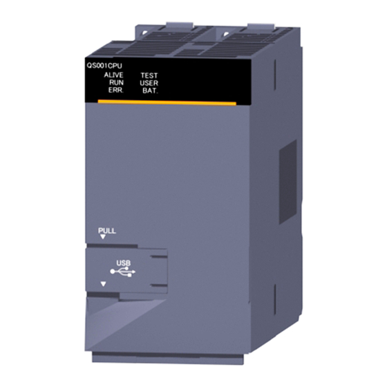
FUNCTIONS 6.18 LED Display The LEDs on the front of the CPU module show the CPU module operation status. QS001CPU ALIVE TEST USER ERR. BAT. Diagram 6.34 LED on CPU module front Remark Refer to the following manual for details of the LED indications. QSCPU User's Manual (Hardware Design, Maintenance and Inspection) 6.18.1 Method to turn off the LED The LED that is on can be turned off by the following operation. -
Page 150: Chapter7 Communication With Intelligent Function Module
COMMUNICATION WITH INTELLIGENT FUNCTION MODULE CHAPTER7 COMMUNICATION WITH INTELLIGENT FUNCTION MODULE 7.1 Communication with CC-Link Safety master module Communication between the CPU modules and the CC-Link Safety master module is executed by auto refresh. To execute link refresh, the refresh parameters need to be set on the Ethernet/CC IE/ MELSECNET setting of Network parameter in GX Developer. -
Page 151: Communication With Cc-Link Ie Controller Network Module Or Melsecnet/H Module
COMMUNICATION WITH INTELLIGENT FUNCTION MODULE 7.2 Communication with CC-Link IE Controller Network Module or MELSECNET/H Module Communication between the CPU module and the CC-Link IE controller network module or MELSECNET/H module is performed by link refresh. To execute link refresh, the refresh parameters need to be set on the *** of Network parameter in GX Developer. -
Page 152: Communication Using Intelligent Function Module Dedicated Instructions
COMMUNICATION WITH INTELLIGENT FUNCTION MODULE 7.4 Communication using intelligent function module dedicated instructions (1) Definition Intelligent function module dedicated instruction is an instruction for realizing easy programming to use the functions of intelligent function modules. (2) Processing of intelligent function module dedicated instructions Some intelligent function module dedicated instructions can specify a completion device. -
Page 153: Chapter8 Parameters
PARAMETERS CHAPTER8 PARAMETERS This chapter explains the parameters need to be set when the programmable controller system is configured. (1) Parameter types There are three types of parameters for the CPU module. • PLC parameters ( Section 8.1) This parameter is set when the programmable controller is used stand-alone. •... -
Page 154: Plc Parameters
PARAMETERS 8.1 PLC Parameters This section shows the list of PLC parameters and explains the details of each parameter setting item. (1) PLC name Set the label and comment of the used CPU module. Setting the label and comment in the PLC name does not affect the actual operation. Diagram 8.1 PLC name Table8.1 PLC name list Item... - Page 155 PARAMETERS (2) PLC system Make the settings necessary to use the CPU module. The parameters may be the default values to perform control. Diagram 8.2 PLC system Table8.2 PLC system setting list Item Parameter No. Description Setting range Default value Reference Low speed 1ms to 1000ms (1ms unit)
- Page 156 PARAMETERS (3) PLC RAS Make the various settings for the RAS function. Diagram 8.3 PLC RAS Table8.3 PLC RAS list Item Parameter No. Description Setting range Default value Reference (watchdog Set the watchdog timer value of 3000 10ms to 2000ms (10ms unit) 200ms Section 3.2 timer)
- Page 157 PARAMETERS (4) Device Set the number of used points and latch range for each device. Diagram 8.4 Device Table8.4 Device list Item Parameter No. Description Setting range Default value Reference : 6k points : 6k points : 6k points X (6k points), Y (6k points), : 2k points 1536, SB (1536 points) and SW : 1k points...
- Page 158 PARAMETERS (5) Boot file Set whether a boot from the standard ROM will be executed or not. Diagram 8.5 Boot file Table8.5 Boot file list Item Parameter No. Description Setting range Default value Reference At TEST MODE, set whether to Do not execute boot/Execute Boot file 7000...
- Page 159 PARAMETERS (6) I/O assignment Set the mounting status of each module in the system. Diagram 8.6 I/O assignment Table8.6 I/O assignment list Item Parameter No. Description Setting range Default value Reference Set the type of the mounted Type Empty/intelli. No setting module.
- Page 160 PARAMETERS (7) X/Y assignment Check the data set on the I/O assignment tab, Ethernet/CC IE/MELSECNET setting, and CC-Link setting. Diagram 8.7 X/Y assignment Table8.7 X/Y assignment list Item Parameter No. Description Setting range Default value Reference The data set in the I/O assignment tab, Ethernet/CC IE/ X/Y assignment ----...
- Page 161 PARAMETERS (8) Safety settings Set the operation settings in continuous RUN in test mode and for remote station error status. Diagram 8.8 Safety settings Table8.8 Safety settings Item Parameter No. Description Setting range Default value Reference Continuous RUN in test Set the continuous RUN 1 second to 86400 seconds 10 seconds...
-
Page 162: Network Parameters
PARAMETERS 8.2 Network Parameters This section shows the list of network parameters and explains the details of each parameter setting item. Definition of mn, M, N in the "Parameter No." column mn, M, N in the "Parameter No." column in this section indicate the following. : Indicates a "start I/O No. - Page 163 PARAMETERS (1) CC-Link IE controller network, MELSECNET/H setting The network parameters for the CC-Link IE controller network and MELSECNET/H are set. Diagram 8.9 Setting the number of Ethernet/CC IE/MELSECNET screen (for CC-Link IE controller network setting) Table8.11 List of CC-Link IE controller network, MELSECNET/H setting items Item Parameter No.
- Page 164 PARAMETERS (2) Ethernet setting The network parameters for the Ethernet are set. Diagram 8.10 Setting the number of Ethernet/CC IE/MELSECNET screen (for Ethernet setting) Table8.12 List of Ethernet setting items Item Parameter No. Description Setting range Default value Reference Number of Ethernet 9000 Starting I/O No.
- Page 165 PARAMETERS (3) CC-Link setting Set the CC-Link parameters. Diagram 8.11 Network parameters Setting the CC-Link list Table8.13 Network parameters Setting the CC-Link list Item Parameter No. Description Setting range Default value Reference Number of CC-Link C000 Starting I/O No. Operational settings Mode setting Transmission settings Safety refresh monitoring...
-
Page 166: Remote Password
PARAMETERS 8.3 Remote Password This section shows the list of remote password-related parameters and explains the details of each parameter setting item. Diagram 8.12 Remote password setting screens The remote password for the Ethernet module is set. Table8.14 List of remote password setting items Item Parameter No. -
Page 167: Chapter9 Device Explanation
DEVICE EXPLANATION CHAPTER9 DEVICE EXPLANATION This chapter describes all devices that can be used in the CPU module. 9.1 Device List The names and data ranges of devices which can be used in the CPU module are shown in Table9.1. Table9.1 Device List Default Values Parameter... -
Page 168: Internal User Devices
DEVICE EXPLANATION 9.2 Internal User Devices (1) Definition Internal user devices can be used for various user applications. The "number of usable points" setting is designated in advance (default value) for internal user devices. However, this setting can be changed at the "Device" tab screen in the "(PLC) Parameter"... - Page 169 DEVICE EXPLANATION (3) Memory capacity Use the following expression to obtain the memory capacity of an internal user device. (Bit device capacity) + (Word device capacity) + (Timer, retentive timer and counter capacity) 12384 words (a) For bit devices: For bit devices, 16 points are calculated as 1 word. (Total number of points of X, Y, M, B, F, SB, V) (words) (Bit device capacity) =...
- Page 170 DEVICE EXPLANATION (4) Device point assignment example A device point assignment example is shown in Table9.2. Table9.2 Device point assignment example *1*2 Restriction check Device Numeric Number of device points Symbol name notation Number of points Number Capacity (Word) Number of bit points Input relay 6k (6144) points X0000 to 17FF 384 words...
-
Page 171: Input (X)
DEVICE EXPLANATION 9.2.1 Input (X) (1) Definition Inputs transmit commands or data to the CPU module from an external device such as push-button switches, selector switches, limit switches, digital switches. Push-button switch Selector switch Input (X) Sequence operation Digital switch Diagram 9.2 Commands from external devices to CPU module (2) Concept of input (X) If the input point is the Xn virtual relay inside the CPU module, the program uses the... - Page 172 DEVICE EXPLANATION POINT 1. When debugging a program, an input (X) can be turned ON/OFF by the following methods. • GX Developer test operation • OUT Xn instruction OUTX100 ON/OFF command X100 Diagram 9.5 Input(X) ON/OFF by the OUT Xn instruction 2.
-
Page 173: Output (Y)
DEVICE EXPLANATION 9.2.2 Output (Y) (1) Definition Outputs give out the program control results to the external devices such as solenoid, electromagnetic switch, signal lamp and digital display. Outputs give out the result equivalent to one N/O contact. Signal lamp Digital display Output (Y) Sequence... -
Page 174: Internal Relay (M)
DEVICE EXPLANATION 9.2.3 Internal relay (M) (1) Definition Internal relays are auxiliary relays used in the CPU module. All internal relays are switched OFF at the following times: • When the PLC is powered OFF and then ON • When the CPU module is reset (2) Number of used N/O and N/C contacts There are no restrictions on the number of contacts (N/O contacts, N/C contacts) used in the program, provided the program capacity is not exceded. -
Page 175: Annunciator (F)
DEVICE EXPLANATION 9.2.4 Annunciator (F) (1) Definition Annunciators are internal relays used for fault detection programs created by the user. (2) Special relay and special registers at annunciator ON When annunciators switch ON, a special relay (SM62) switches ON, and the Nos. and quantity of the annunciators which switched ON are stored at the special registers (SD62 to 79). - Page 176 DEVICE EXPLANATION (4) Number of used N/O and N/C contacts There are no restrictions on the number of contacts (N/O contacts, NC contacts) used in the program, provided the program capacity is not exceeded. (5) Annunciator ON procedure (a) Annunciator ON procedure The annunciator can be turned ON by either of the following instructions.
- Page 177 DEVICE EXPLANATION (b) Processing at annunciator ON 1) Data stored at special registers (SD62 to 79) • Nos. of annunciators which switched ON are stored in order at SD64 to • The annunciator No. which was stored at SD64 is stored at SD62. •...
- Page 178 DEVICE EXPLANATION (6) Annunciator OFF procedure and processing content (a) Annunciator OFF procedure The annunciator can be turned OFF by any of the following instructions. 1) RST F instruction The RST F instruction turns OFF an annunciator at leading eggs (OFF to ON) of the input condition.
- Page 179 DEVICE EXPLANATION (b) Processing at annunciator OFF 1) Special register (SD62 to 79) data operation when annunciator is tunred OFF by executing the RST F instruction • The annunciator No. specified by the RST instruction is deleted, and the stored annunciator Nos. after the deleted annunciator No. are shifted up. •...
-
Page 180: Edge Relay (V)
DEVICE EXPLANATION 9.2.5 Edge relay (V) (1) Definition An edge relay is a device which stores the operation results (ON/OFF information) from the beginning of the ladder block. Edge relays can only be used at contacts, and cannot be used as coils. X100 X102 X104 Edge relay Stores the X100, X102 and... -
Page 181: Link Relay (B)
DEVICE EXPLANATION 9.2.6 Link relay (B) (1) Definition Link relay is a CPU module side relay used when refreshing the link relay (LB) data of the CC-Link IE controller network module or MELSECNET/H module to the CPU module, or when refreshing the CPU module data to the link relays (LB) of the CC- Link IE controller network module or MELSECNET/H module. - Page 182 DEVICE EXPLANATION (3) Using link relays in the network system In order to use link relays in the network system, a network parameter setting is required. Link relays in the range where network parameters have not been set (not used by the CC-Link IE controller network or MELSECNET/H) can be used as internal relays.
-
Page 183: Link Special Relay (Sb)
DEVICE EXPLANATION 9.2.7 Link special relay (SB) (1) Definition Link special relay is a relay used to indicate the communication status and error detection of the CC-Link Safety master module, CC-Link IE controller network module, and MELSECNET/H module. ON/OFF of the link special relays are controlled by various causes that occur during data link. -
Page 184: Timer (T)
DEVICE EXPLANATION 9.2.8 Timer (T) (1) Definition A timer (T) is a device that starts counting when its coil turns ON, and times-out and turns ON its contact when the current value reaches or exceeds the set value. The timer is of an up-counting type. The current value matches the set value when a "time-out"... - Page 185 DEVICE EXPLANATION (b) Measurement units The default time measurement units setting for low speed timers is 100 ms. The time measurement units setting can be designated in 1 ms units within a 1 ms to 1000 ms range. This setting is designated at the "PLC system" tab screen in the "(PLC) Parameter"...
- Page 186 DEVICE EXPLANATION (6) Retentive timers (a) Definition Retentive timers measure the "coil ON" time. The measurement begins when the timer coil switches ON, and the contact switches ON when a time-out (coil OFF) occurs. Even when the timer coil is OFF, the current value and the contact ON/OFF status are saved.
- Page 187 DEVICE EXPLANATION (7) Timer Processing and accuracy (a) Processing method When an OUT T instruction is executed, the following is processed: timer coil ON/OFF, current value update and contact ON/OFF processing. Timer current value update and contact ON/OFF processing are not performed at END processing.
- Page 188 DEVICE EXPLANATION (b) Accuracy Measured value at END instruction is added to the current value when the OUT T instruction is executed. If the timer coil is OFF when the OUT T instruction is executed, the current value is not updated. [Ladder example] X100 [Current value update timing]...
- Page 189 DEVICE EXPLANATION (8) Precautions for using timers The following are a few precautions regarding timer use: (a) Use of the same timer A given timer cannot be designated (by OUT T ) more than once in a single scan. This designation results in measurement, since the timer current value is updated at execution of each OUT T instruction.
-
Page 190: Counter (C)
DEVICE EXPLANATION 9.2.9 Counter (C) (1) Definition A counter is a device which counts the number of input condition leading edges in sequence programs. When the count value matches the set value, the counter counts up and its contact turns ON. The counter is of an up-counting type. - Page 191 DEVICE EXPLANATION (b) Current value update (count value + 1) The current value update (count value + 1) is performed at the leading edge (OFF to ON) of the OUT C instruction. The current value is not updated in the following OUT C instruction statuses: OFF, ON to ON, ON to OFF [Ladder example]...
- Page 192 DEVICE EXPLANATION (c) Resetting the counter Counter current values are not cleared even if the OUT C instruction switches OFF. Use the RST C instruction to clear the counter's current value and switch the contact OFF. The count value is cleared and the contact is switched OFF at execution of when the RST C instruction.
- Page 193 DEVICE EXPLANATION RST C0 RST C0 OUT C0 OUT C0 Sequence program Coil of C0 Current value is updated Current value update since coil of C0 turns & contact ON Coil of C0 OFF from OFF to ON. RST C0 Count value cleared &...
-
Page 194: Data Register (D)
DEVICE EXPLANATION 9.2.10 Data register (D) (1) Definition Data registers are memory devices which store numeric data (-32768 to 32767, or 0000 to FFFF (2) Bit configuration of data register (a) Bit configuration and read and write units Data registers, which consist of 16 bits per point, read and write data in 16-bit units. -
Page 195: Link Register (W)
DEVICE EXPLANATION 9.2.11 Link register (W) (1) Definition Link register is a CPU module side memory used when refreshing the link register (LW) data of the CC-Link IE controller network module or MELSECNET/H module to the CPU module. CC-Link IE controller network module CPU module Link register... - Page 196 DEVICE EXPLANATION (b) When link register is used for 32-bit instruction If the link registers are used for 32-bit instructions, the data is stored in registers Wn and Wn + 1. The lower 16 bits of data are stored in the link register No. (Wn) designated in the sequence program, and the higher 16 bits of data are stored in the designated register No.
-
Page 197: Link Special Register (Sw)
DEVICE EXPLANATION (4) Using link registers in a network system In order to use link registers in the network system, network parameter settings must be made. Link registers not set in the network parameter settings can be used as data registers. Remark For the network parameters, refer to the following manuals. -
Page 198: Internal System Devices
DEVICE EXPLANATION 9.3 Internal System Devices Internal system devices are used for system operations. The allocations and sizes of internal system devices are fixed, and cannot be changed by the user. 9.3.1 Special relay (SM) (1) Definition Special relay stores the CPU module states (error diagnostics, system information, etc.). -
Page 199: Special Register (Sd)
DEVICE EXPLANATION 9.3.2 Special register (SD) (1) Definition A special register is used to store CPU module status data (error diagnostics and system information). (2) Special register classifications Special registers are classified according to their applications, as shown in Table9.6. Table9.6 Special register classification list Classification Special register... -
Page 200: Nesting (N)
DEVICE EXPLANATION 9.4 Nesting (N) (1) Definition Nesting is a device used in the master control instruction (MC instruction, MCR instruction) to program operation conditions in a nesting structure. (2) Specifying method in master control instruction The master control instruction opens/closes a common ladder bus to create a sequence program of efficient ladder switching. -
Page 201: Constants
DEVICE EXPLANATION 9.5 Constants 9.5.1 Decimal constant (K) (1) Definition Decimal constants are devices that designate decimal data in sequence programs. Specify it as K (example: K1234) in a sequence program. It is stored in binary (BIN) into the CPU module. ( Section 3.7.1) (2) Designation range The designation ranges for decimal constants are as follows:... -
Page 202: Chapter10 Cpu Module Processing Time
CPU MODULE PROCESSING TIME CHAPTER10 CPU MODULE PROCESSING TIME This chapter explains the CPU module processing time. 10.1 Scan Time This section explains the scan time structures and CPU module processing time. 10.1.1 structure and calculation of scan time (1) Scan time structure The CPU module scan time consists of the followings processings. - Page 203 CPU MODULE PROCESSING TIME (2) Calculation of scan time scan time is calculated from the following formula. SM = Tru + Tio + Tie + Tend + Ts + Tc (ms) • SM :Scan time Module refresh time • Tru : /O refresh time •...
-
Page 204: Time Required For Each Processing Included In Scan Time
CPU MODULE PROCESSING TIME 10.1.2 Time required for each processing included in scan time This section explains how to calculate the processing and execution times shown in Section 10.1.1. (1) I/O refresh time I/O refresh time is the refresh time for I/O data between the CC-Link Safety master module, CC-Link IE controller network module or MELSECNET/H module and the CPU module. - Page 205 CPU MODULE PROCESSING TIME (4) Service processing time Service processing is the processing for communication with GX Developer and external devices. • Monitoring by GX Developer Processing times required for monitoring by GX Developer are shown below. Table10.3 Monitor processing time by GX Developer Function QS001CPU 5.6ms...
- Page 206 CPU MODULE PROCESSING TIME (5) Module refresh time Module refresh time is the total time for the link refresh of CC-Link IE controller network or MELSECNET/H and the auto refresh of CC-Link Safety set in the network parameters. (a) CC-Link IE controller network refresh time This is the time required to refresh data between the link devices of the CC-Link IE controller network module and the devices of the CPU module.
-
Page 207: Factors That Increase The Scan Time
CPU MODULE PROCESSING TIME 10.1.3 Factors that increase the scan time When the following functions or operations are performed, this will increase the scan time of the CPU module. When executing any of them, make sure to allow for the processing time (the value given in this section to the value calculated in Section 10.1.2). -
Page 208: Other Processing Times
CPU MODULE PROCESSING TIME 10.2 Other Processing Times This section explains the processing times other than those described in Section 10.1. (1) Constant scan accuracy Table10.6 indicates the constant scan accuracy. Table10.6 Constant scan accuracy CPU module Constant scan accuracy QS001CPU With monitor : Indicates the status in which monitor is being executed with GX Developer... -
Page 209: Chapter11 Procedure For Writing Program To Cpu Module 11 - 1 To
PROCEDURE FOR WRITING PROGRAM TO CPU MODULE CHAPTER11 PROCEDURE FOR WRITING PROGRAM TO CPU MODULE This chapter describes the procedure for writing program created at the GX Developer to the CPU module. The CPU module startup procedure is not described in this manual. Refer to the following manuals for the CPU module startup procedure. -
Page 210: Procedure For Writing Program
PROCEDURE FOR WRITING PROGRAM TO CPU MODULE 11.2 Procedure for writing program This section explains the procedure for writing the parameters and program created by GX Developer to the CPU module. This section explains the procedure for writing a program to the program memory ( Section 5.1.2). - Page 211 PROCEDURE FOR WRITING PROGRAM TO CPU MODULE Connect the personal computer, which is installed with GX Developer, to the CPU module. Set the RUN/STOP/RESET switch to the STOP position, and power ON the PLC (the "ERR". LED turns on). Set the CPU access password in GX Developer and register it in the CPU module.
-
Page 212: Boot Run Procedure
PROCEDURE FOR WRITING PROGRAM TO CPU MODULE 11.3 Boot run procedure This section explains a boot run procedure. In the following procedure, indicates the operation on the GX Developer side, and indicates that on the CPU module side. Section 11.2 Start (Continued from Section 11.1.3) When the RUN/STOP/RESET switch is in the RUN position, set the switch to... -
Page 213: Appendices
APPENDICES APPENDICES Appendix 1 Special Relay List Special relays, SM, are internal relays whose applications are fixed in the PLC. For this reason, they cannot be used by sequence programs in the same way as the normal internal relays. However, they can be turned ON or OFF as needed in order to control the CPU module and remote I/O modules. - Page 214 APPENDICES (1) Diagnostic Information TableApp.2 Descriptions of the special relay headings Set by Corresponding Number Name Meaning Explanation (When Set) • Turns ON when an error is detected by diagnostics Diagnostic OFF : No error (Includes when an annunciator is ON) S (Error) errors ON : Error...
- Page 215 APPENDICES (2) System information TableApp.3 Special relay Set by Corresponding Number Name Meaning Explanation (When Set) SM203 STOP contact STOP status • Turns ON when the CPU is in STOP status. S (Status change) • Writes clock data stored in SD210 to SD213 Clock data set OFF : Ignored to the CPU module after the END instruction...
- Page 216 APPENDICES (4) Safety CPU TableApp.5 Special relay Set by Corresponding Number Name Meaning Explanation (When Set) • Turns ON when operating on the TEST OFF : Other than TEST MODE. TEST MODE SM560 MODE • Turns OFF when operating on the other S (Status change) flag mode (SAFETY MODE, SAFETY MODE...
-
Page 217: Appendix 2 Special Register List
APPENDICES Appendix 2 Special Register List The special registers, SD, are internal registers with fixed applications in the PLC. For this reason, it is not possible to use these registers in sequence programs in the same way that normal registers are used. However, data can be written as needed in order to control the CPU modules and remote I/ O modules. - Page 218 APPENDICES (1) Diagnostic Information TableApp.10 Special register Set by Corresponding Number Name Meaning Explanation (When set) • Error codes for errors detected by diagnostics are stored as Diagnostic Diagnosis error BIN data. S (Error) errors code • Contents identical to latest fault history information. •...
- Page 219 APPENDICES TableApp.10 Special register Set by Corresponding Number Name Meaning Explanation (When set) • Common information corresponding to the error codes (SD0) is stored here. • The following six types of information are stored here: Module No./Base No. Number Meaning Slot No./Base No.
- Page 220 APPENDICES TableApp.10 Special register Set by Corresponding Number Name Meaning Explanation (When set) Time (value set) Number Meaning Time : 1 s units (0 to 999 s) Time : 1ms units (0 to 65535ms) SD10 (Empty) SD11 SD12 SD13 SD14 SD15 Program error location Meaning...
- Page 221 APPENDICES TableApp.10 Special register Set by Corresponding Number Name Meaning Explanation (When set) • Individual information corresponding to error codes (SD0) is stored here. • There are the following nine different types of information are SD16 stored. File name/Drive name Meaning (Example) File name = Number...
- Page 222 APPENDICES TableApp.10 Special register Set by Corresponding Number Name Meaning Explanation (When set) 10) CC-Link Safety information SD16 Meaning Number SD16 Number of items for individual information individual information 1 SD17 SD18 individual information 2 SD17 SD19 individual information 3 individual information 4 SD20 SD21...
- Page 223 APPENDICES TableApp.10 Special register Set by Corresponding Number Name Meaning Explanation (When set) I/O module I/O module • The lowest I/O number of the module where the I/O module SD61 verify error verify error S (Error) verification number took place. number module number Annunciator...
- Page 224 APPENDICES TableApp.10 Special register Set by Corresponding Number Name Meaning Explanation (When set) • When I/O modules, of which data are different from those entered at power-on, have been detected, the I/O module SD150 numbers (in units of 16 points) are entered in bit pattern. Bit pattern, in (Preset I/O module numbers set in parmeters when parameter units of 16...
- Page 225 APPENDICES TableApp.12 Special register Set by Corresponding Number Name Meaning Explanation (When set) • The year (last two digits) and month are stored as BCD code at SD210 as shown below: Clock data Example: SD210 Clock data September, 2006 (year, month) 0609 Year Month...
- Page 226 APPENDICES TableApp.12 Special register Set by Corresponding Number Name Meaning Explanation (When set) Loaded Loaded maximum • The upper 2 digits of the final I/O number plus 1 of the SD250 S (Initial) maximum I/O I/O No. modules loaded are stored as BIN values. Number of •...
- Page 227 APPENDICES (3) System clocks/counters TableApp.13 Special register Set by Corresponding Number Name Meaning Explanation (When set) Number of • Following programmable controller CPU module RUN, 1 is 1 second S (Status SD412 counts in 1- added each second counter change) second units •...
- Page 228 APPENDICES (5) Safety CPU TableApp.15 Special register Set by Corresponding Number Name Meaning Explanation (When set) • Stores the safety CPU operation mode. b2 b1b0 Safety CPU Empty Safety CPU S (Status SD560 operation operation mode change) 00 : SAFETY MODE mode 01 : TEST MODE 10 : SAFETY MODE...
- Page 229 APPENDICES (7) CC-Link Safety TableApp.17 Special register Set by Corresponding Number Name Meaning Explanation (When set) • The specified status of safety remote station is stored. • "0" is stored for the standard remote station. Safety remote 0: No safety station remote station SD1000...
- Page 230 APPENDICES TableApp.17 Special register Set by Corresponding Number Name Meaning Explanation (When set) Cancel the I/O interlock of safety station by changing the bit of register from 0 to 1. 0: Not cancel the Safety station I/O interlock interlock SD1076 of safety SD1076 cancel request...
- Page 231 APPENDICES TableApp.17 Special register Set by Corresponding Number Name Meaning Explanation (When set) Bit corresponding to the station number turns 1 when the master station goes to the interlock status after the error was detected at the master station. Safety station interlock 0: Interlock is SD1272...
-
Page 232: Appendix 3 Parameter Number List
APPENDICES Appendix 3 Parameter Number List The parameter number is stored into the special register (SD16 to 26) when an error occurs in the parameter settings. This section describes the parameter number and the corresponding parameter setting area (item) in the list. TableApp.18 Parameter number list Item Parameter No. - Page 233 APPENDICES TableApp.18 Parameter number list (continued) Item Parameter No. Referance Section 6.9 Constant scanning 3003 Section 8.1(3) CC-Link IE Setting the number of MELSECNET 5000 Starting I/O No. controller 5NM0 Network No. network, Mode 5NM0 Section 8.2(1) MELSECNET/H Refresh parameters 5NM1 setting Station No...
- Page 234 APPENDICES Appendix 4 Restrictions on Using CC-Link IE Controller Network Module with Safety CPU Module (1) Network parameters which can be set in the safety CPU module TableApp.19 lists the network parameters for CC-Link IE controller network and their setting availability with GX Developer when the CC-Link IE controller network is used with the safety CPU module.
- Page 235 APPENDICES (2) CC-Link IE controller network functions which can be used in the safety CPU module TableApp.20 lists the functions of CC-Link IE controller network and their availability in the safety CPU module. TableApp.20 List of CC-Link IE controller network functions and their availability in safety CPU module Function Availability Communication by LB/LW...
- Page 236 APPENDICES TableApp.20 List of CC-Link IE controller network functions and their availability in safety CPU module (continued) Function Availability Hardware test Self-loopback test Line test Diagnostic function Station-to-station test Network test Communication test Interrupt request to CPU module Station No. setting by sequence program : Available, : Not available * 1: Data cannot be written to the safety CPU module from the CPU module on another station.
-
Page 237: Appendix 5 Restrictions On Using Melsecnet/H Module With Safety Cpu Module
APPENDICES Appendix 5 Restrictions on Using MELSECNET/H Module with Safety CPU Module (1) Network parameters which can be set in the safety CPU module TableApp.21 lists the network parameters for MELSECNET/H and their setting availability with GX Developer when the MELSECNET/H module is used with the safety CPU module. - Page 238 APPENDICES (2) MELSECNET/H network system functions which can be used in the safety CPU module TableApp.22 lists the functions of MELSECNET/H and their availability in the safety CPU module. TableApp.22 List of MELSECNET/H functions and their availability in safety CPU module Function Availability Communication by LB/LW...
- Page 239 APPENDICES TableApp.22 List of CC-Link IE controller network functions and their availability in safety CPU module (continued) Function Availability Direct access to link devices Interrupt sequence program startup Multiplex transmission function (optical loop system) Simple dual-structured network function Cyclic transmission stop/restart and link refresh stop (network test) Increasing number of send points by installing multiple module with the same network number Multiple CPU system support Remote I/O system...
-
Page 240: Appendix 6 Restrictions On Using Ethernet Module With Safety Cpu Module
APPENDICES Appendix 6 Restrictions on Using Ethernet Module with Safety CPU Module (1) Network parameters which can be set in the safety CPU module TableApp.23 lists the network parameters for Ethernet and their setting availability with GX Developer when the Ethernet module is used with the safety CPU module. TableApp.23 List of network parameters and their setting availability with GX Developer Item Setting availability... - Page 241 APPENDICES (2) Ethernet functions which can be used in the safety CPU module TableApp.24 lists the functions of Ethernet and their availability in the safety CPU module. TableApp.24 List of Ethernet functions and their availability in the safety CPU module Function Availability Using 4E frame...
- Page 242 APPENDICES (3) MC protocol which can be used in the safety CPU module TableApp.25 and TableApp.26 list the data communication functions using the MC protocol and their availability in the safety CPU module. (a) 4E frame and QnA-compatible 3E frame TableApp.25 List of MC protocol functions (4E frame and QnA-compatible 3E frame) and their availability in the safety CPU module Command Function...
- Page 243 APPENDICES TableApp.25 List of MC protocol functions (4E frame and QnA-compatible 3E frame) and their availability in the safety CPU module (continued) Command Function Type Availability (Subcommand) Directory/file information read ---- 1810(0000) Directory/file information search ---- 1811(0000) New file creation ---- 1820(0000) File delete...
- Page 244 APPENDICES (b) A-compatible 1E frame TableApp.26 List of MC protocol functions (4E frame and QnA-compatible 3E frame) and their availability in the safety CPU module Command Function Type Availability (Subcommand) Batch read Word Batch write Word Test (Random write) File Word Monitor data registration Word...
-
Page 245: Appendix 7 Dedicated Instructions Which Can Be Used In Safety Cpu Module
APPENDICES Appendix 7 Dedicated Instructions which can be used in Safety CPU Module Appendix 7.1 List of dedicated instructions (1) Dedicated instructions which can be used in the safety CPU module TableApp.27 lists the dedicated instructions which can be used in the safety CPU module. - Page 246 APPENDICES (2) Dedicated instructions which can be used from the CPU module on another station to the safety CPU module TableApp.28 lists the dedicated instructions which can be used from the CPU module on another station to the safety CPU module. TableApp.28 List of available dedicated instructions Supported network Dedicated...
-
Page 247: Appendix 7.2 Programming Using Dedicated Instructions
APPENDICES Appendix 7.2 Programming using dedicated instructions Since the safety CPU module does not support the intelligent function module device (U ) and the FROM/TO instructions, data stored in the buffer memory of the intelligent function module cannot be used in the sequence program of the safety CPU module. To use data stored in the buffer memory of the intelligent function module in the sequence program of the safety CPU module, use I/O signals, which correspond to the buffer memory, of the intelligent function module. - Page 248 APPENDICES (1) OPEN instruction Fig.App.1 shows a program example where buffer memory addresses are replaced with I/O signals in the program for Active-opening the connection No.1 for TCP/IP communication. TableApp.30 Buffer memory address - I/O signal correspondence Buffer memory address I/O signal in hexadecimal (decimal) 5000...
- Page 249 APPENDICES (2) CLOSE instruction Fig.App.2 shows a program example where buffer memory addresses are replaced with I/O signals in the program for closing the connection No.1. TableApp.31 Buffer memory address - I/O signal correspondence Buffer memory address I/O signal in hexadecimal (decimal) 5000 (20480): Open completion signal X10: Connection 1 open completion...
- Page 250 APPENDICES (3) BUFRCV instruction Fig.App.3 shows a program example where buffer memory addresses are replaced with I/O signals in the program for reading received data from the fixed buffer of the connection No.1. TableApp.32 Buffer memory address - I/O signal correspondence Buffer memory address I/O signal in hexadecimal (decimal)
- Page 251 APPENDICES (4) BUFSND instruction Fig.App.4 shows a program example where buffer memory addresses are replaced with I/O signals in the program for sending data from the fixed buffer of the connection No.1. TableApp.33 Buffer memory address - I/O signal correspondence Buffer memory address I/O signal in hexadecimal (decimal)
- Page 252 APPENDICES (5) UINI instruction Fig.App.5 shows a program example where buffer memory addresses are replaced with I/O signals in the program for reinitialize the Ethernet module. TableApp.34 Buffer memory address - I/O signal correspondence Buffer memory address I/O signal in hexadecimal (decimal) 5000 (20480): Open completion signal X10: Connection 1 open completion...
-
Page 253: Appendix 8 Access Range For Safety Cpu Module
APPENDICES Appendix 8 Access Range for Safety CPU Module The following shows an access range and accessibility from GX Developer and a GOT to a safety CPU module. The safety CPU module does not perform routing between Ethernet and CC-Link IE controller network or between Ethernet and MELSECNET/H. - Page 254 APPENDICES TableApp.35 Accessibility Access target Access source QSCPU QSCPU QCPU QCPU QSCPU QCPU QCPU QSCPU QCPU QCPU QCPU QCPU GX Developer A0 GOT A0 GX Developer A1 GX Developer A2 GX Developer B2 G4 A2 GOT A2 GX Developer A3 GX Developer A4 GX Developer A4' (A4)
-
Page 255: Appendix 9 Safety Cpu Module Upgrade
APPENDICES Appendix 9 Safety CPU Module Upgrade (1) Additional functions and availability of the functions according to the version of GX Developer TableApp.36 Additional functions and availability of the functions according to the version of GX Developer Compatible Compatible GX New function Compatible serial No. -
Page 256: Index
INDEX [0] to [9] Timer [T] ......2-2 Device list ....... 9-1 5VDC internal current consumption . - Page 257 Link special register (SW) ....9-31 Link special register [SW] ....2-2 Safety settings .
- Page 258 Memo Index...
- Page 259 1. Limited Warranty and Product Support. a. Mitsubishi Electric Company ("MELCO") warrants that for a period of eighteen (18) months after date of delivery from the point of manufacture or one year from date of Customer's purchase, whichever is less, Mitsubishi MELSEC Safety programmable logic controllers (the "Products") will be free from defects in material and workmanship.
- Page 260 (11) damaged or malfunctioning due to Acts of God, fires, acts of vandals, criminals or terrorists, communication or power failures, or any other cause or failure that results from circumstances beyond MELCO's control. f. All Product information and specifications contained on MELCO's website and in catalogs, manuals, or technical information materials provided by MELCO are subject to change without prior notice.
- Page 261 6. Arbitration. Any controversy or claim arising out of, or relating to or in connection with the Products, their sale or use or these terms, shall be settled by arbitration conducted in accordance with the Center for Public Resources (CPR) Rules for Non-Administered Arbitration of International Disputes, by a sole arbitrator chosen from the CPR's panels of distinguished neutrals.
- Page 262 Microsoft, Windows, Windows NT, and Windows Vista are registered trademarks of Microsoft Corporation in the United States and other countries. Pentium is a trademark of Intel Corporation in the United States and other countries. Ethernet is a trademark of Xerox Corporation. All other company names and product names used in this manual are trademarks or registered trademarks of their respective companies.
Need help?
Do you have a question about the MELSEC QS Series and is the answer not in the manual?
Questions and answers