Table of Contents
Advertisement
Quick Links
Mitsubishi Safety Programmable Controller
Thank you for purchasing the Mitsubishi safety programmable
controller MELSEC-QS Series.
Prior to use, please read both this manual and detailed manual
thoroughly and familiarize yourself with the product.
© 2008 MITSUBISHI ELECTRIC CORPORATION
CC-Link Safety System
Remote I/O Module
QS0J65BTS2-8D
MODEL
MODEL
CODE
IB(NA)-0800414-A(0804)MEE
User's Manual
(Hardware)
QS0J65BTS2-8D-U-HW
13JY66
Advertisement
Table of Contents

Related Manuals for Mitsubishi Melsec QS Series


Summary of Contents for Mitsubishi Melsec QS Series
- Page 1 CC-Link Safety System Remote I/O Module User’s Manual (Hardware) QS0J65BTS2-8D Thank you for purchasing the Mitsubishi safety programmable controller MELSEC-QS Series. Prior to use, please read both this manual and detailed manual thoroughly and familiarize yourself with the product. MODEL...
- Page 2 SAFETY PRECAUTIONS (Always read these instructions before using this product.) Before using the product, please read this manual, the relevant manuals introduced in this manual, standard PLC manuals, and the safety standards carefully and pay full attention to safety to handle the product correctly. This manual contains precautions for this product only.
- Page 3 [Design Precautions] DANGER When a safety PLC detects an error in an external power supply or a failure in PLC main module, it turns off all the outputs. Create an external circuit to securely stop the power of hazard by turning off the outputs.
- Page 4 [Installation Precautions] CAUTION Use a safety PLC in the environment that meets the general specifications described in the QSCPU User's Manual (Hardware Design, Maintenance and Inspection). Using this PLC in an environment outside the range of the general specifications could result in electric shock, fire, erroneous operation, and damage to or deterioration of the product.
- Page 5 [Wiring Precautions] CAUTION Ground the FG and LG terminals correctly. Not doing so could result in electric shock or malfunctions. Wire the module correctly after confirming the rated voltage and terminal layout. Connecting a power supply of a different rated voltage or incorrect wiring may cause a fire or failure.
- Page 6 [Startup and Maintenance Precautions] DANGER Do not touch the terminals while power is on. Doing so could result in electric shock. Turn off all phases of the external supply power used in the system when cleaning the module or retightening the terminal block mounting screws, terminal screws, or module mounting screws.
- Page 7 IB(NA)-0800414-A First printing This manual confers no industrial property rights or any rights of any other kind, nor does it confer any patent licenses. Mitsubishi electric Corporation cannot be held responsible for any problems involving industrial property rights which may occur as a result of using the contents noted in this manual.
-
Page 8: Table Of Contents
CONTENTS 1. Overview ......................1 2. Specifications ....................2 2.1 General Specifications ................2 2.2 Performance Specifications ..............3 2.3 Cable Specifications ................5 2.4 Confirming Production Information ............5 3. Part Names and Settings ................6 4. Mounting and Installation ................9 4.1 Handling Precautions ................ - Page 9 (13JR89) Conformance to the EMC and Low Voltage Directives When incorporating the Mitsubishi PLC compliant with the EMC and Low Voltage Directives into other industrial machinery and ensuring compliance with the directives, refer to Chapter 3 "EMC and Low Voltage Directives" of the QSCPU User's Manual (Hardware).
-
Page 10: Overview
1. Overview This manual explains the specifications and handling and wiring methods of the safety remote I/O module for the CC-Link Safety System. After unpacking, confirm that the following are included. Item Quantity QS0J65BTS2-8D CC-Link Safety System Remote I/O Module User's Manual (Hardware)QS0J65BTS2-8D... -
Page 11: Specifications
2. Specifications 2.1 General Specifications The general specifications of the QS0J65BTS2-8D are shown below. Item Specification Operating ambient 0 to 55°C temperature Storage ambient -40 to 75°C temperature Operating ambient non-condensing 5 to 95%RH, humidity non-condensing Storage ambient humidity 5 to 95%RH, Frequency Constant Half... -
Page 12: Performance Specifications
2.2 Performance Specifications The performance specifications of the QS0J65BTS2-8D are shown below. DC input module Item QS0J65BTS2-8D No. of input points 8 points (Input terminals: 16 points Isolation method Photocoupler Rated input voltage 24V DC Rated input current Approx. 5.9mA Operating voltage range 19.2V to 28.8V DC (Ripple ratio: 5% or less) Maximum number of... - Page 13 • TE1 (Nichifu) [Applicable wire size: 0.9 to 1.0mm Applicable • TE1.5 (Nichifu) [Applicable wire size: 1.25 to 1.5mm solderless • FA-VTC125T9 (Mitsubishi Electric Engineering Co.,Ltd. terminal [Applicable wire size: 0.3 to 1.65mm • FA-VTCW125T9 (Mitsubishi Electric Engineering Co.,Ltd. [Applicable wire size:0.3 to 1.65mm...
-
Page 14: Cable Specifications
2.3 Cable Specifications Use dedicated CC-Link cables for the CC-Link Safety System. The performance of the CC-Link Safety System cannot be guaranteed when any other cables are used. For the specifications or any other inquiries, visit the following website: CC-Link Partner Association: http://www.cc-link.org/ Remarks For details, refer to the CC-Link Cable Wiring Manual issued by the CC-Link Partner Association. -
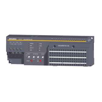
Page 15: Part Names And Settings
3. Part Names and Settings The name of each part in the QS0J65BTS2-8D is shown. - Page 16 Name Description LED name Indication Indicates the power status of the safety remote I/O module. "POWER" ON (green) : Normally powered : Powered off or error occurred (blown fuse) Indicates the operating status of the safety remote I/O module. ON (green) : Normally operating, or moderate error occurred "RUN"...
- Page 17 Name Description Setting Description 0 to 7 Link ID setting Setting for reading error logs 2) Link ID setting switch Setting for self-loopback test To update the changed switch setting, reset or power OFF and ON the safety remote I/O module. Set station No.
-
Page 18: Mounting And Installation
4. Mounting and Installation 4.1 Handling Precautions This section provides handling precautions for use of the safety remote I/O module. Do not touch the terminals while power is on. DANGER Doing so could cause shock or erroneous operation. Be sure there are no foreign substances such as sawdust CAUTION or wiring debris inside the module. - Page 19 Make sure to fix a CC-Link Safety remote I/O module with CAUTION a DIN rail or mounting screws and tighten the screws with the specified torque. If the screws are too loose, it may cause a drop of the screw or module. Over tightening may cause a drop due to the damage of the screw or module.
-
Page 20: Installation Environment
(7) When using a DIN rail, pay attention to the following: (a) Applicable DIN rail model (conforming to JIS C 2812) TH35-7.5Fe TH35-7.5Al (b) Installation screw intervals Tighten the screws at pitches of 200mm (7.88 inch) or less. (8) When installing the safety remote I/O module to the DIN rail, press the center part of the hook located on the bottom of the module until a click is heard. -
Page 21: Wiring
5. Wiring 5.1 Precautions for Handling CC-Link Cables This section explains how to handle dedicated CC-Link cables. Do not perform any of the following, as each of them will damage CC-Link cables: • Compressing the cable with a sharp object •... -
Page 22: Precautions For Wiring Module Power Supply
5.3 Precautions for Wiring Module Power Supply When wiring the module power supply of the safety remote I/O module, note the following. • Cable length of the module power supply must be within10m 5.4 Precautions for Wiring Safety Devices This section describes precautions for wiring to each safety device. (1) Wiring of the input terminal section (a) Combinations of input terminals Input terminals can be used in the following combinations only. -
Page 23: External Dimensions
6. External Dimensions Mounting pitch 188.4 4.5(0.18) mounting hole 9 (0.35) (7.42) (M4 mounting screw) (0.18) DIN rail center (7.76) Unit: mm (inch) - Page 24 Please confirm the following product warranty details before using this product. 1. Limited Warranty and Product Support. a. Mitsubishi Electric Company ("MELCO") warrants that for a period of forty two(42) months after date of delivery from the point of manufacture or three(3) years from date of Customer's purchase, whichever is less, Mitsubishi MELSEC Safety programmable controllers (the "Products") will be free from defects in material and workmanship.
- Page 25 2. Limits of Warranties. a. MELCO does not warrant or guarantee the design, specify, manufacture, construction or installation of the materials, construction criteria, functionality, use, properties or other characteristics of the equipment, systems, or production lines into which the Products may be incorporated, including any safety, fail-safe and shut down systems using the Products.
- Page 26 3. Limits on Damages. a. MELCO'S MAXIMUM CUMULATIVE LIABILITY BASED ON ANY CLAIMS FOR BREACH OF WARRANTY OR CONTRACT, NEGLIGENCE, STRICT TORT LIABILITY OR OTHER THEORIES OF RECOVERY REGARDING THE SALE, REPAIR, REPLACEMENT, DELIVERY, PERFORMANCE, CONDITION, SUITABILITY, COMPLIANCE, OR OTHER ASPECTS OF THE PRODUCTS OR THEIR SALE, INSTALLATION OR USE SHALL BE LIMITED TO THE PRICE PAID FOR PRODUCTS NOT AS WARRANTED.
- Page 27 4. Delivery/Force Majeure. a. Any delivery date for the Products acknowledged by MELCO is an estimated and not a promised date. MELCO will make all reasonable efforts to meet the delivery schedule set forth in Customer's order or the purchase contract but shall not be liable for failure to do b.
- Page 28 Hsiang, Taipei Hsine, Taiwan Gothaer Strasse 8 D-40880 Ratingen, Tel : +886-2-2299-2499 GERMANY Tel : +49-2102-486-0 Korea Mitsubishi Electric Automation Korea Co., Ltd. 1480-6, Gayang-dong, Gangseo-ku Mitsubishi Electric Europe B.V. UK Seoul 157-200, Korea Branch Tel : +82-2-3660-9552 Travellers Lane, Hatfield, Hertfordshire., AL10 8XB, U.K.
Need help?
Do you have a question about the Melsec QS Series and is the answer not in the manual?
Questions and answers